5v vs. 3.3v Pro Mini battery powered nodes
-
A video here https://www.youtube.com/watch?v=kEkD4SLMX8Y on some different ways to power the Pro Mini
-
There are no thoughts. Just get 3.3v pro mini.
Generally speaking for any low consumption (battery driven nodes), try to get rid of 5v devices (chips or sensors). I have moved completely to 3.3v almost without regulators with exception of the solar /supercap node. -
There are no thoughts. Just get 3.3v pro mini.
Generally speaking for any low consumption (battery driven nodes), try to get rid of 5v devices (chips or sensors). I have moved completely to 3.3v almost without regulators with exception of the solar /supercap node. -
@mhkid For battery powered sensors, you should always try to go 3V3. And if necessary change the model of sensor. At 3V3 the consumption is lower as well, so you win twice the energy (very roughly). Your device should also sleep continuously between the sensor captures. It can become tricky. But I used a DHT22+328p+TI CC RF sensor powered by 3V3 on a single AA cell and up-converter for 5 years now, and I only need to recharge it every 4-6 month.
-
A video here https://www.youtube.com/watch?v=kEkD4SLMX8Y on some different ways to power the Pro Mini
@maah This video doesn't show different ways to power an arduino it's talking about power consumption. I'm already removing the regulator, LED and sleeping it. I'm more asking about battery powered nodes with sensors than are more than 3.3v. How are people feeding 5v to these sensors?
-
@alexsh1 like I said of course it would be preferred to use the 3v sensors but that's not always possible. My question is more about what are people doing when they are using a battery powered node with a 5v sensor.
@mhkid replace the sensor. If you cannot replace the sensor, you have several options:
-
use 5v pro mini + 3xAA batteries + 5v sensor.
This is going to be a very power hungry setup. -
use 3.3v pro mini + level shifter + 3xAA batteries + 5v sensor
Again this setup now ideal - you have to drop voltage from 5v to 3.3v
I still have several old 5v sensors I used with Arduino Uno. I am just not using them any longer with one exceptions when a node is powered from mains.
-
-
@mhkid replace the sensor. If you cannot replace the sensor, you have several options:
-
use 5v pro mini + 3xAA batteries + 5v sensor.
This is going to be a very power hungry setup. -
use 3.3v pro mini + level shifter + 3xAA batteries + 5v sensor
Again this setup now ideal - you have to drop voltage from 5v to 3.3v
I still have several old 5v sensors I used with Arduino Uno. I am just not using them any longer with one exceptions when a node is powered from mains.
@alexsh1 Which sensor should I replace the water pressure sensor with?
-
-
@alexsh1 Which sensor should I replace the water pressure sensor with?
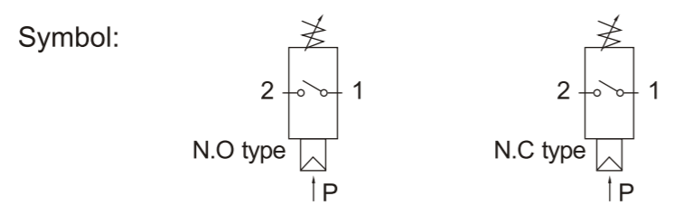
@mhkid IF the objective is only to detect supply pressure failure rather than monitor pressure over time for process reasons, why not use a pressure switch set between max supply pressure and Zero? Your processor sleeps until the switch detects a fall in pressure and wakens the processor to call home ?
https://www.ebay.com/itm/1-8-QPM11-NC-Pressure-Switch-Wire-External-Thread-Nozzle-Adjustable/272843081265?hash=item3f86b70631:g:iJcAAOSwKnVZtrP~ Perhaps ?
There are undoubtedly plenty of other alternatives, on the expensive side there is always RS etc.... -
@alexsh1 Which sensor should I replace the water pressure sensor with?
-
@mhkid I cannot see the consumption. Do you have the datasheet?
Most likely this is not a battery friendly sensor. In this case you stil can use it via a step up converter and TPL5110, which will switchit off completely while sleeping
@alexsh1 it is a mechanical switch, just like a button or reed switch.
https://www.google.nl/url?sa=t&source=web&rct=j&url=http://www.cneni.com/cn/file.asp%3FFilename%3Dupload/products/download/2009_10_29_16_27_30_150570.pdf&ved=2ahUKEwjZgbb605LcAhWG-qQKHXHjC6YQFjAOegQIABAB&usg=AOvVaw2MqIOPIURwEs_sa7VMGGoi@zboblamont nice find :+1:
http://yveaux.blogspot.nl
-
@alexsh1 it is a mechanical switch, just like a button or reed switch.
https://www.google.nl/url?sa=t&source=web&rct=j&url=http://www.cneni.com/cn/file.asp%3FFilename%3Dupload/products/download/2009_10_29_16_27_30_150570.pdf&ved=2ahUKEwjZgbb605LcAhWG-qQKHXHjC6YQFjAOegQIABAB&usg=AOvVaw2MqIOPIURwEs_sa7VMGGoi@zboblamont nice find :+1:
-
Thanks for all the suggestions and replies. I'll take all the info, weigh the options and then report back on what I end up doing.
@mhkid Another option for you is using TPL5110 module:
https://www.adafruit.com/product/3435
I have just received one today and going to tinker with it.
To me it seems like a good idea to have a powerful sensors with Arduino on batteries. -
@mhkid Another option for you is using TPL5110 module:
https://www.adafruit.com/product/3435
I have just received one today and going to tinker with it.
To me it seems like a good idea to have a powerful sensors with Arduino on batteries. -
@yveaux Maximum operating current - 500mA. It depends how often the pressure is going to change, but one can pretty much forget about batteries as the source of power.
-
@alexsh1 look at the schematic; it is just a mechanical switch with 2 wires. It can probably only carry 500ma max.
@yveaux Are you sure you are not talking at crossed purposes about different devices? The device @mhkid was originally referring to is the one with the 5v supply requirement, Circuit hopefully below.
 image url)
The one I suggested as a low pressure alarm actuator was a variable pressure switch, which may be the one you are referring to... -
@yveaux Are you sure you are not talking at crossed purposes about different devices? The device @mhkid was originally referring to is the one with the 5v supply requirement, Circuit hopefully below.

The one I suggested as a low pressure alarm actuator was a variable pressure switch, which may be the one you are referring to...@zboblamont Mine is a lot simpler :laughing:
@alexsh1 Mea culpa, too many crosslinked discussions; apparently I lost track.
Still, I like your sensor better @zboblamont
http://yveaux.blogspot.nl
-
@zboblamont Mine is a lot simpler :laughing:
@alexsh1 Mea culpa, too many crosslinked discussions; apparently I lost track.
Still, I like your sensor better @zboblamont
@yveaux My suggestion is very simple. If there is a device which consumes more than > 5-50uA sleeping on a battery powered node, it has to be completely disconnected while sleeping. This is where TPL5110 comes in. Obviously if an interrupt is used it does not work
-
@yveaux My suggestion is very simple. If there is a device which consumes more than > 5-50uA sleeping on a battery powered node, it has to be completely disconnected while sleeping. This is where TPL5110 comes in. Obviously if an interrupt is used it does not work
@alexsh1 Much the same principal as my 5v/3v solution for the 5v ultrasonic, only here I used a latching relay leaving the 3v Arduino on sleep power consumption.
An interesting device however, with a low standby and effectively a timer function, it has many possibilities.Where this original project has been skewed is unfortunate, the selected devices compel the dual voltage solution, whereas an alternative strategy removes the need for it completely.
Although pulses and switches can be regarded as "old" technology, they can still be highly effective for battery powered applications where energy conservation is critical..
Hello! It looks like you're interested in this conversation, but you don't have an account yet.
Getting fed up of having to scroll through the same posts each visit? When you register for an account, you'll always come back to exactly where you were before, and choose to be notified of new replies (either via email, or push notification). You'll also be able to save bookmarks and upvote posts to show your appreciation to other community members.
With your input, this post could be even better 💗
Register Login