Microwave Radar Module as PIR replacement.
-
@Yveaux From my oppinion the radar modules are not suited for battery usage. Their drain something like 3-5mA and are not easy to put to sleep. Remember the warm-up period of the BISS. It seems to be like 10-15seconds.
The plots are from another sketch, not the one I posted but using them is pretty straight forward.
In my sketch have a look at these parts:
  Serial << "| mw_min: ";
  int minimum = mw_s.minimum();
  p(F("%4d"),minimum);
  Serial << " ";
To use the arduino plotting all you ahve to do is send a string like this:
0,10,534,123 .. whatever .. beware that no other serial output should happen if you want to use the arduino build-in plotting. Using the streaming library ( http://arduiniana.org/libraries/streaming/ ) it all boils down to a single line:
Serial << mw_s.minimum() << "," << mw_s.maximum() << "," << mw_s.pop_stdev() << endl;In addition to the power consumption my approach requires sampling the analog input for a whole second .. or the more the better.
This might be improved if you can prevent the FC1816 from retriggering itself. I had some serious problems as during the "inhibitor" period the analogOutput from the 2nd amplification stage was quite high often instantly retrigger the biss-output after the inhibition period ended.
One solution might be this:
Try this if you want to look down this approch:
- Power the FC1816 VCC and UDP through an RC-Section (100Ohm Resistor and after that (on the side of the FC1816) an capacitory ~100-220µF)
- Replace amplification resistor from 105 to eg. 154 (lowering the amplification)
To find the best value I used an variable resistor parallel to the 105-Ohms SMD-Resistor
But .. don't forget the benefits of *he microwave sensor. You can mount it straight to a door and it would detect persons in front of the door without them noticing. For this reason I try to build an "Alarm-node" that can be hidden inside the house. Later I might improve the FC1816 with some aluminium foil for shielding as suggested earlier.
I would suggest using an PIR if you need a battery powered node. Have a look at ( http://kavacky.lv/bypassing-sen-08630-pir-motion-sensors-voltage-regulator-to-work-with-3-3-v ). Some PIRs have a Regulator which might not be suited if you are running on battery using 3,3Volt.
-
All things from my previous post regarding the wiring are still needed:
Here is a stripped down example on how to use the FC1816 Microwave Sensor. You need the following library:
https://github.com/RobTillaart/Arduino/tree/master/libraries/Statistic
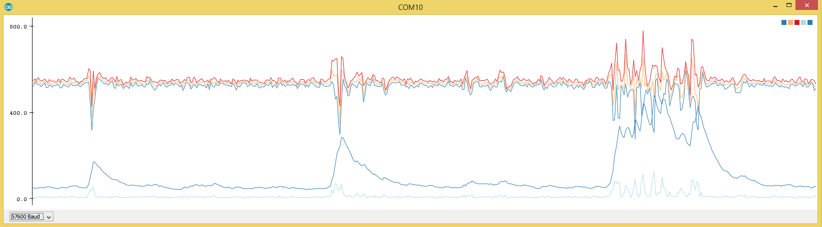
#include "Statistic.h"

#define MICRO_SENSOR_ANALOG_PIN A1

void setup()
{

  Serial.begin(57600);
  Serial.print("begin");

  // Microwave
  pinMode(5,OUTPUT);        // VCC BISS0001
  digitalWrite(5,HIGH);

  pinMode(6,OUTPUT);        // Enabled
  digitalWrite(6,LOW);      // DISABLE PLEASE!

  pinMode(7,OUTPUT);        // GND
  digitalWrite(7,LOW);

  pinMode(A1,INPUT);        // PIR 2nd amplification stage

  pinMode(A0,OUTPUT);       // UPD microwave generator
  digitalWrite(A0,HIGH);

}

void loop()
{
  // Report Microwave
  static Statistic mw_s;
  static uint16_t stdev_sum = 0;
  //mw_s.clear();

  //digitalWrite(8,HIGH);
  //delay(100);
  analogRead(MICRO_SENSOR_ANALOG_PIN);
  uint16_t reading;
  for(int i = 0; i < 200; i++)
  {
    reading = analogRead(MICRO_SENSOR_ANALOG_PIN);
    mw_s.add(reading);
    //Serial.println(reading);
    //Serial.flush();
    //delay(50);
    //LowPower.powerDown(SLEEP_60MS, ADC_ON, BOD_OFF);
    //delay(1);
  }
  Serial.print(mw_s.minimum());   Serial.print(",");
  Serial.print(mw_s.average());   Serial.print(",");
  Serial.print(mw_s.maximum());   Serial.print(",");
  Serial.print(mw_s.pop_stdev()); Serial.print(",");
  stdev_sum += mw_s.pop_stdev();
  Serial.print(stdev_sum); //Serial.print(",");
  Serial.println();
  stdev_sum *= 0.9;
  mw_s.clear();
}
I just had the idea to sum up the std-dev and decrease it by 10% every round. Thus the code is less prone to peaks.
stdev_sum is the lower dark blue line which can now be much easier compared to a threshold.
Some measurement with my µCurrent-Gold:
Unmodified code as above, power LED removed from ProMini @ 8Mhz internal osci with LDO desoldered
4,8mAI tried to put the FC1816 into sleep by disable the power to the Microwave generator but this doesn't work.
I modified the fuses for 8Mhz with 0ms wakeup delay for stabelizing the oscillator. No risk no phun ;-)The most practical solution I got to replace a PIR (still nothing as close as a PIR ;-ö)
1530µA
with this code:
Note that the radar generator just can't be disable as it needs 10-15seconds to stabelize after power up
#include <LowPower.h> #include "Statistic.h" #define MICRO_SENSOR_ANALOG_PIN A1 void setup() { Serial.begin(57600); Serial.print("begin"); // Microwave pinMode(5,OUTPUT); // VCC BISS0001 digitalWrite(5,HIGH); pinMode(6,OUTPUT); // Enabled digitalWrite(6,LOW); // DISABLE PLEASE! pinMode(7,OUTPUT); // GND digitalWrite(7,LOW); pinMode(A1,INPUT); // PIR 2nd amplification stage pinMode(A0,OUTPUT); // UPD microwave generator digitalWrite(A0,HIGH); } void loop() { // Report Microwave static Statistic mw_s; static uint16_t stdev_sum = 0; //mw_s.clear(); //delay(100); analogRead(MICRO_SENSOR_ANALOG_PIN); uint16_t reading; for(int i = 0; i < 10; i++) { LowPower.powerDown(SLEEP_15Ms, ADC_ON, BOD_OFF); reading = analogRead(MICRO_SENSOR_ANALOG_PIN); mw_s.add(reading); //Serial.println(reading); //Serial.flush(); //delay(50); LowPower.powerDown(SLEEP_15Ms, ADC_ON, BOD_OFF); //delay(1); } Serial.print(mw_s.minimum()); Serial.print(","); Serial.print(mw_s.average()); Serial.print(","); Serial.print(mw_s.maximum()); Serial.print(","); Serial.print(mw_s.pop_stdev()); Serial.print(","); stdev_sum += mw_s.pop_stdev(); Serial.print(stdev_sum); //Serial.print(","); Serial.println(); Serial.flush(); stdev_sum *= 0.9; mw_s.clear(); } -
All things from my previous post regarding the wiring are still needed:
Here is a stripped down example on how to use the FC1816 Microwave Sensor. You need the following library:
https://github.com/RobTillaart/Arduino/tree/master/libraries/Statistic
#include "Statistic.h"

#define MICRO_SENSOR_ANALOG_PIN A1

void setup()
{

  Serial.begin(57600);
  Serial.print("begin");

  // Microwave
  pinMode(5,OUTPUT);        // VCC BISS0001
  digitalWrite(5,HIGH);

  pinMode(6,OUTPUT);        // Enabled
  digitalWrite(6,LOW);      // DISABLE PLEASE!

  pinMode(7,OUTPUT);        // GND
  digitalWrite(7,LOW);

  pinMode(A1,INPUT);        // PIR 2nd amplification stage

  pinMode(A0,OUTPUT);       // UPD microwave generator
  digitalWrite(A0,HIGH);

}

void loop()
{
  // Report Microwave
  static Statistic mw_s;
  static uint16_t stdev_sum = 0;
  //mw_s.clear();

  //digitalWrite(8,HIGH);
  //delay(100);
  analogRead(MICRO_SENSOR_ANALOG_PIN);
  uint16_t reading;
  for(int i = 0; i < 200; i++)
  {
    reading = analogRead(MICRO_SENSOR_ANALOG_PIN);
    mw_s.add(reading);
    //Serial.println(reading);
    //Serial.flush();
    //delay(50);
    //LowPower.powerDown(SLEEP_60MS, ADC_ON, BOD_OFF);
    //delay(1);
  }
  Serial.print(mw_s.minimum());   Serial.print(",");
  Serial.print(mw_s.average());   Serial.print(",");
  Serial.print(mw_s.maximum());   Serial.print(",");
  Serial.print(mw_s.pop_stdev()); Serial.print(",");
  stdev_sum += mw_s.pop_stdev();
  Serial.print(stdev_sum); //Serial.print(",");
  Serial.println();
  stdev_sum *= 0.9;
  mw_s.clear();
}
I just had the idea to sum up the std-dev and decrease it by 10% every round. Thus the code is less prone to peaks.
stdev_sum is the lower dark blue line which can now be much easier compared to a threshold.
Some measurement with my µCurrent-Gold:
Unmodified code as above, power LED removed from ProMini @ 8Mhz internal osci with LDO desoldered
4,8mAI tried to put the FC1816 into sleep by disable the power to the Microwave generator but this doesn't work.
I modified the fuses for 8Mhz with 0ms wakeup delay for stabelizing the oscillator. No risk no phun ;-)The most practical solution I got to replace a PIR (still nothing as close as a PIR ;-ö)
1530µA
with this code:
Note that the radar generator just can't be disable as it needs 10-15seconds to stabelize after power up
#include <LowPower.h> #include "Statistic.h" #define MICRO_SENSOR_ANALOG_PIN A1 void setup() { Serial.begin(57600); Serial.print("begin"); // Microwave pinMode(5,OUTPUT); // VCC BISS0001 digitalWrite(5,HIGH); pinMode(6,OUTPUT); // Enabled digitalWrite(6,LOW); // DISABLE PLEASE! pinMode(7,OUTPUT); // GND digitalWrite(7,LOW); pinMode(A1,INPUT); // PIR 2nd amplification stage pinMode(A0,OUTPUT); // UPD microwave generator digitalWrite(A0,HIGH); } void loop() { // Report Microwave static Statistic mw_s; static uint16_t stdev_sum = 0; //mw_s.clear(); //delay(100); analogRead(MICRO_SENSOR_ANALOG_PIN); uint16_t reading; for(int i = 0; i < 10; i++) { LowPower.powerDown(SLEEP_15Ms, ADC_ON, BOD_OFF); reading = analogRead(MICRO_SENSOR_ANALOG_PIN); mw_s.add(reading); //Serial.println(reading); //Serial.flush(); //delay(50); LowPower.powerDown(SLEEP_15Ms, ADC_ON, BOD_OFF); //delay(1); } Serial.print(mw_s.minimum()); Serial.print(","); Serial.print(mw_s.average()); Serial.print(","); Serial.print(mw_s.maximum()); Serial.print(","); Serial.print(mw_s.pop_stdev()); Serial.print(","); stdev_sum += mw_s.pop_stdev(); Serial.print(stdev_sum); //Serial.print(","); Serial.println(); Serial.flush(); stdev_sum *= 0.9; mw_s.clear(); } -
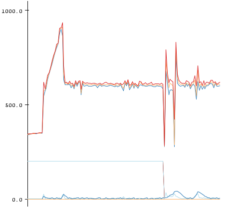
After a few more days of testing I noticed these ugly "PEAKS" from my FC1816 readings. I added lots of capacitors and RC and LC sections but still .. nasty little peaks (left side in the beginning)
In my previous post replace this line:
stdev_sum += mw_s.pop_stdev();with this:
  // Ignore the first 3 peaks within short succession
  // Real movement should mean there are more peaks/activity over a long time
  static uint8_t peakcount = 0;
  if(mw_s.pop_stdev() > 30 && peakcount < 3)
  {
    peakcount++;
  }
  else
  {
    stdev_sum += mw_s.pop_stdev();
    stdev_sum *= 0.92; //
    if (stdev_sum >= 7)
      stdev_sum -= 7; // Default background noise
    if (stdev_sum > 512)
      stdev_sum = 512;

    if(peakcount > 0)
      peakcount--;
  }
With this code the first 3 peaks are essentially removed .. if there is really some movement it should last for a few seconds and would still be detected.
I have invested like 10-20hours into testing and debugging the FC1816 and I can say .. this thing is .. peculiar ..
I hate it cause of the spikes, the amplification which has to be manually altered with a pot .. but at the same time I love it ..
I can detect my foot beckoning 2-3meters apart in my bed :D
An example of the code snipped in action:
Here you can see the big spikes in the beginning completely ignored (1)
-
After a few more days of testing I noticed these ugly "PEAKS" from my FC1816 readings. I added lots of capacitors and RC and LC sections but still .. nasty little peaks (left side in the beginning)
In my previous post replace this line:
stdev_sum += mw_s.pop_stdev();with this:
  // Ignore the first 3 peaks within short succession
  // Real movement should mean there are more peaks/activity over a long time
  static uint8_t peakcount = 0;
  if(mw_s.pop_stdev() > 30 && peakcount < 3)
  {
    peakcount++;
  }
  else
  {
    stdev_sum += mw_s.pop_stdev();
    stdev_sum *= 0.92; //
    if (stdev_sum >= 7)
      stdev_sum -= 7; // Default background noise
    if (stdev_sum > 512)
      stdev_sum = 512;

    if(peakcount > 0)
      peakcount--;
  }
With this code the first 3 peaks are essentially removed .. if there is really some movement it should last for a few seconds and would still be detected.
I have invested like 10-20hours into testing and debugging the FC1816 and I can say .. this thing is .. peculiar ..
I hate it cause of the spikes, the amplification which has to be manually altered with a pot .. but at the same time I love it ..
I can detect my foot beckoning 2-3meters apart in my bed :D
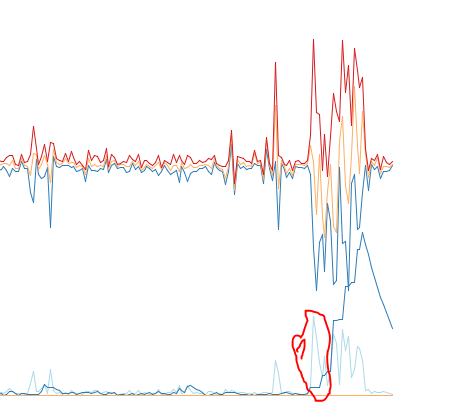
An example of the code snipped in action:
Here you can see the big spikes in the beginning completely ignored (1)
-
Currently I don't plan to make a library .. a library implies that the sensor is very easy to use .. plug in + import library.
The FC1816 is not such a sensor.
- Needs Voltage-Supply filter (RC Section)
- Need separate cable to grab the signal at the 2nd amplification stage
- Need potentiometer to lower the amplification
- Is very prone to random noise (in fact even entering RF24 or ATMEGA328 low power mode might increase noise floor a lot)
Using a "simple to use" library and not getting the expected result of an "easy"-sensor would be very disappointing. For now I would say this is an advanced sensor with some pitfalls.
I update this thread with my findings to hopefully make everybodys life a bit easyer if you want to tinker with the FC1816 although you now know it is a little beast ;-)
If you need any help just ask here and I will support you the best I can.
-
It's a review of some radar sensors if anyone is interested.
-
Does anyone have a complete MySensors sketch for these that they would be willing to share?
I tried to create a wildlife sensor with it a while ago.. but the signal seemed to always be high.
-
Does anyone have a complete MySensors sketch for these that they would be willing to share?
I tried to create a wildlife sensor with it a while ago.. but the signal seemed to always be high.
I when the tested here is such:
They work great on an almost standard PIR MOTION sketch
..By the way why no one makes these motion sensors MW for MySensors on openhardware, it seems there is nothing complicated?
-
Does anyone have a complete MySensors sketch for these that they would be willing to share?
I tried to create a wildlife sensor with it a while ago.. but the signal seemed to always be high.
@alowhum
Now I remembered that I once shot a video about this sensor. In the description below the video there are links to sketches that work with such sensors. But for this video I did not do subtitles in English, in sketches comments also seem to be in Russian. But I think it won't be a problem.
Hello! It looks like you're interested in this conversation, but you don't have an account yet.
Getting fed up of having to scroll through the same posts each visit? When you register for an account, you'll always come back to exactly where you were before, and choose to be notified of new replies (either via email, or push notification). You'll also be able to save bookmarks and upvote posts to show your appreciation to other community members.
With your input, this post could be even better 💗
Register Login