LED Dimmer not working as it should
-
Thanks for your reply!
The Arduino I am using is the Mini Pro. I looked into the pins and PWM and yes you are correct, so I have changed the pin that I use from Pin 4 to Pin 3, which does support PWM.
Your comment relating to the issue with the chosen MOSFET doesn't apply because I am using 12 Volt.
The strip that I am currently testing with is 80cm. This strip requires a little less than 1 amp, and I am currently using a 12 volt power supply that pushes out 2 amp. I power the arduino through the RAW pin.
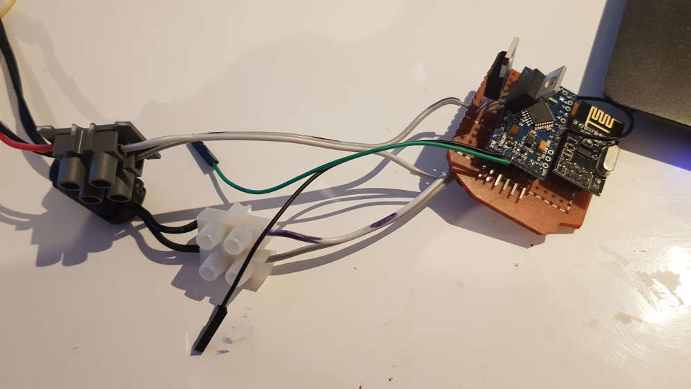
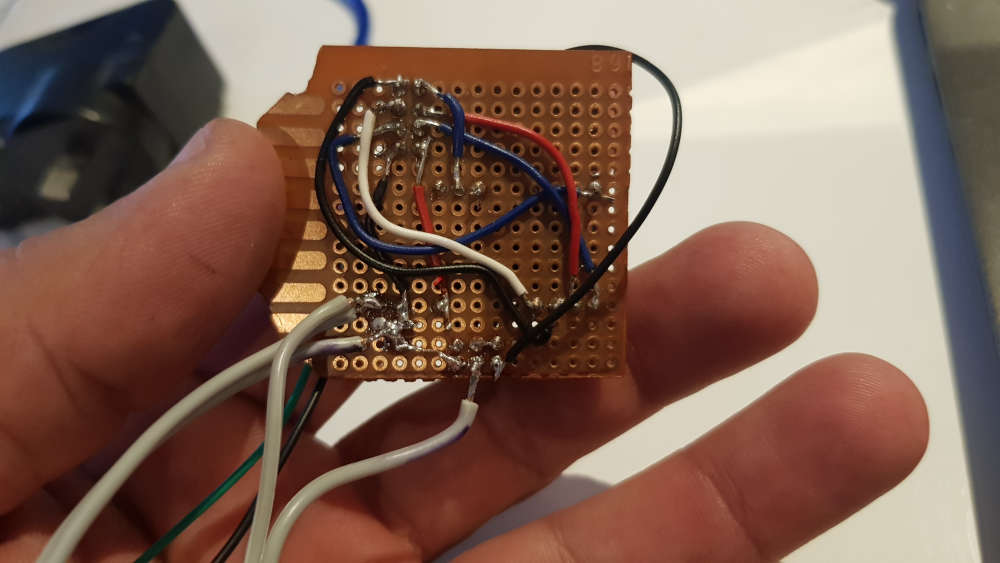
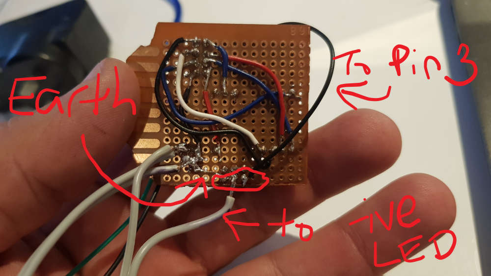
I am not sure what you mean when you ask how the gate was connected to the microcontroller, so I have taken a couple pics which I hope will help. Please excuse my soldering skills. You will also see two MOSFETs on the board; this is because I was originally using a different one until I visited my local electronics store and bought different ones. The old one wouldn't come of the board easily so in this case I just left it there.
@homer said in LED Dimmer not working as it should:
Your comment relating to the issue with the chosen MOSFET doesn't apply because I am using 12 Volt.
Well, actually I think it does apply ;-)
Your LED strip runs on 12V, but the PWM pin 3 is directly connected to the Mosfet, correct?
If this is the case, the Mosfet will only partially switch on when driven at 5V (or are you using a 3.3V pro mini, which would be even worse...)
See e.g. https://arduinodiy.wordpress.com/2012/05/02/using-mosfets-with-ttl-levels/You'll need e.g. an extra transistor inbetween (see the IRF522 schematic) to make sure it switches on completely when driven by the Arduino, or use a logic level Mosfet.
Does the mosfet heat up when switchen on by the Arduino?
Does your LED strip light much brighter when the mosfet is driven by 12V at the gate? (use a separate Mosfet to test, disconnected from your board!) -
Thanks again so much for taking the time to reply! I do appreciate it!
In regards to my comment which was related to your comment about the chosen MOSFET, I honestly thought you had made a mistake and thought I was driving the LED's using 5v, but I now see that this is not what you meant.It looks like the biggest mistake I made here was my choice of MOSFET. And yes, my pro mini is a 3.3v version.
[This is my local electronics store](link url), so I will have another read of the last link you provided and try and work out which MOSFET will better suit my needs.
I don't know if the mosfet heats up, I haven't had it running long enough to know. I don't know what you mean when you say "at the gate"; I think I have a lot more reading to do!
Again I appreciate your help!
-
I just found that there is another local store here which I have used a few years ago and now allow pickups.
I think this is the one I should get. I will also get myself a 10k resistor and include that in the circuit.
-
@homer that seems to be the better choice when driven directly by the microcontroller indeed!
-
I finally got around to picking up the new MOSFET's. I can confirm that as suggested, they were the issue. It is now working like I had hoped!
But I do have a problem, maybe.... when I had the serial monitor going it seemed to be doing an awful lot, which leads me to believe that there might be something wrong with the code. Can you experts here please check my code and provide feedback? It will be very much appreciated!!!!
Here is my sketch:
// Enable debug prints to serial monitor #define MY_DEBUG #define MY_REPEATER_FEATURE // Enable and select radio type attached #define MY_RADIO_RF24 //#define MY_RADIO_NRF5_ESB //#define MY_RADIO_RFM69 //#define MY_RADIO_RFM95 #include <MySensors.h> #define SN "DimmableLED and Motion" #define SV "1.1" // setup LED stuff #define LED_PIN 3 // Arduino pin attached to MOSFET Gate pin #define FADE_DELAY 10 // Delay in ms for each percentage fade up/down (10ms = 1s full-range dim) // setup Motion stuff uint32_t WAIT_TIME = 120000; // Sleep time between reports (in milliseconds) #define DIGITAL_INPUT_SENSOR 4 // The digital input you attached your motion sensor. #define CHILD_ID 1 // Id of the sensor child static int16_t currentLevel = 0; // Current dim level... MyMessage dimmerMsg(0, V_DIMMER); MyMessage lightMsg(0, V_LIGHT); MyMessage msg(CHILD_ID, V_TRIPPED); /*** * Dimmable LED initialization method */ void setup() { // Pull the gateway's current dim level - restore light level upon node power-up request( 0, V_DIMMER ); pinMode(DIGITAL_INPUT_SENSOR, INPUT); // sets the motion sensor digital pin as input } void presentation() { // Register the LED Dimmable Light with the gateway present( 0, S_DIMMER ); present(CHILD_ID, S_MOTION); sendSketchInfo(SN, SV); } /*** * Dimmable LED main processing loop */ void loop() { // Read digital motion value bool tripped = digitalRead(DIGITAL_INPUT_SENSOR) == HIGH; Serial.println(tripped); send(msg.set(tripped?"1":"0")); // Send tripped value to gw } void receive(const MyMessage &message) { if (message.type == V_LIGHT || message.type == V_DIMMER) { // Retrieve the power or dim level from the incoming request message int requestedLevel = atoi( message.data ); // Adjust incoming level if this is a V_LIGHT variable update [0 == off, 1 == on] requestedLevel *= ( message.type == V_LIGHT ? 100 : 1 ); // Clip incoming level to valid range of 0 to 100 requestedLevel = requestedLevel > 100 ? 100 : requestedLevel; requestedLevel = requestedLevel < 0 ? 0 : requestedLevel; Serial.print( "Changing level to " ); Serial.print( requestedLevel ); Serial.print( ", from " ); Serial.println( currentLevel ); fadeToLevel( requestedLevel ); // Inform the gateway of the current DimmableLED's SwitchPower1 and LoadLevelStatus value... send(lightMsg.set(currentLevel > 0)); // hek comment: Is this really nessesary? send( dimmerMsg.set(currentLevel) ); // Sleep until interrupt comes in on motion sensor. Send update every two minute. sleep(digitalPinToInterrupt(DIGITAL_INPUT_SENSOR), CHANGE, WAIT_TIME); } } /*** * This method provides a graceful fade up/down effect */ void fadeToLevel( int toLevel ) { int delta = ( toLevel - currentLevel ) < 0 ? -1 : 1; while ( currentLevel != toLevel ) { currentLevel += delta; analogWrite( LED_PIN, (int)(currentLevel / 100. * 255) ); delay( FADE_DELAY ); } }``` -
@homer sleeping and sending from within receive() won't work. Move those to loop().
Loop in your current sketch will send an endless stream of messages, with no pause. That's wasteful.
@mfalkvidd Thank you
I had merged the example LED strip and motion sketches to get what I had and somehow I made a couple mistakes in the process.
I don't want the sensor to sleep. I had thought I had done enough within the sketch to just have it wait, but I think I have solved that now. When merging the sketches I had moved the wait part from loop to receive, which has now been rectified along with changing it to wait. I hope that it will work correctly; I have set the wait time for 1.5 seconds. I think I understand it right; this wait will only impact the repeater function rather than the motion sensor?
The adjusted sketch compiles, and I will upload it soon to my sensor. I have tidied the sketch up a bit and here it is:
/** Here is the motion sketch example merged with the LED strip example. Instead of sleeping, it uses wait. This is because this sensor is also a Repeater */ // Enable debug prints to serial monitor #define MY_DEBUG // Enable the repeater feature #define MY_REPEATER_FEATURE // Enable and select radio type attached #define MY_RADIO_RF24 #include <MySensors.h> #define SN "DimmableLED and Motion" #define SV "1.2" // setup LED stuff #define LED_PIN 3 // Arduino pin attached to MOSFET Gate pin #define FADE_DELAY 10 // Delay in ms for each percentage fade up/down (10ms = 1s full-range dim) // setup Motion stuff uint32_t WAIT_TIME = 1500; // Wait time between reports (in milliseconds) Current value (2000) is 1.5 seconds. #define DIGITAL_INPUT_SENSOR 4 // The digital input you attached your motion sensor. #define CHILD_ID 1 // Id of the sensor child static int16_t currentLevel = 0; // Current dim level... MyMessage dimmerMsg(0, V_DIMMER); MyMessage lightMsg(0, V_LIGHT); MyMessage msg(CHILD_ID, V_TRIPPED); void setup() { // Pull the gateway's current dim level - restore light level upon node power-up request( 0, V_DIMMER ); pinMode(DIGITAL_INPUT_SENSOR, INPUT); // sets the motion sensor digital pin as input } void presentation() { // Register sensors with the gateway present( 0, S_DIMMER ); present(CHILD_ID, S_MOTION); sendSketchInfo(SN, SV); } void loop() { // Read digital motion value bool tripped = digitalRead(DIGITAL_INPUT_SENSOR) == HIGH; Serial.println(tripped); send(msg.set(tripped ? "1" : "0")); // Send tripped value to gw // Wait until interrupt comes in on motion sensor. Send update every 1.5 seconds. wait(digitalPinToInterrupt(DIGITAL_INPUT_SENSOR), CHANGE, WAIT_TIME); } void receive(const MyMessage &message) { if (message.type == V_LIGHT || message.type == V_DIMMER) { // Retrieve the power or dim level from the incoming request message int requestedLevel = atoi( message.data ); // Adjust incoming level if this is a V_LIGHT variable update [0 == off, 1 == on] requestedLevel *= ( message.type == V_LIGHT ? 100 : 1 ); // Clip incoming level to valid range of 0 to 100 requestedLevel = requestedLevel > 100 ? 100 : requestedLevel; requestedLevel = requestedLevel < 0 ? 0 : requestedLevel; Serial.print( "Changing level to " ); Serial.print( requestedLevel ); Serial.print( ", from " ); Serial.println( currentLevel ); fadeToLevel( requestedLevel ); // Inform the gateway of the current DimmableLED's SwitchPower1 and LoadLevelStatus value... send(lightMsg.set(currentLevel > 0)); send( dimmerMsg.set(currentLevel) ); } } /*** This method provides a graceful fade up/down effect */ void fadeToLevel( int toLevel ) { int delta = ( toLevel - currentLevel ) < 0 ? -1 : 1; while ( currentLevel != toLevel ) { currentLevel += delta; analogWrite( LED_PIN, (int)(currentLevel / 100. * 255) ); delay( FADE_DELAY ); } }``` -
OK.... I have decided to not have this sensor as a repeater, which means I can let it sleep. But I still have problems...
I read that only pins 2 and 3 have interrupt, so I moved the motion sensor to pin 3. This was where the LED strip was connected so I moved it to pin 5, as this pin is supposed to also have PWM. So it now should work, right? Nope lol
The motion sensor is working as it should, but the LED strip is no longer working. Apparently pins 3,5,6,9 and 11 all provide 8 bit PWM so I am going to try each pin at a time and see how I go, because those specs are for genuine Mini Pro and I don't think mine is the real deal and that could mean that the pins have been setup differently.
Time to start testing :-) :-)
-
Haha I've just worked out why breadboards are so useful!!! I've been playing around with the hardware so much that it looks like some connections have gone bad. I think I have everything setup right and working, but the lights won't go on until I have the Arduino in my hand lol
I don't think I feel like pulling this one apart and redoing it, so I'm going to start from scratch with another one and see how I go.
-
After lots of testing, I can confirm that the issue I have must be related to the sketch. The LED lights will flicker like mad. Sometimes it stops, but it is always momentarily. Sometimes the light can even be controlled so it brightens or dims, but again it's only briefly. When I wipe the arduino and upload a identical sketch but just without the motion sensing, the LED light works exactly as it should.
Here is the problem sketch which hopefully someone can point me in the right direction :-)
/** Here is the motion sketch example merged with the LED strip example. Instead of sleeping, it uses wait. This is because this sensor is also a Repeater */ // Enable debug prints to serial monitor #define MY_DEBUG // Enable and select radio type attached #define MY_RADIO_RF24 #include <MySensors.h> #define SN "DimmableLED and Motion" #define SV "1.4" // setup LED stuff #define LED_PIN 5 // Arduino pin attached to MOSFET Gate pin #define FADE_DELAY 15 // Delay in ms for each percentage fade up/down (10ms = 1s full-range dim) // setup Motion stuff uint32_t SLEEP_TIME = 120000; // Sleep time between reports (in milliseconds) #define DIGITAL_INPUT_SENSOR 3 // The digital input you attached your motion sensor. #define CHILD_ID 1 // Id of the sensor child static int16_t currentLevel = 0; // Current dim level... MyMessage dimmerMsg(0, V_DIMMER); MyMessage lightMsg(0, V_LIGHT); MyMessage msg(CHILD_ID, V_TRIPPED); void setup() { // Pull the gateway's current dim level - restore light level upon node power-up request( 0, V_DIMMER ); pinMode(DIGITAL_INPUT_SENSOR, INPUT); // sets the motion sensor digital pin as input } void presentation() { // Register sensors with the gateway present( 0, S_DIMMER ); present(CHILD_ID, S_MOTION); sendSketchInfo(SN, SV); } void loop() { // Read digital motion value bool tripped = digitalRead(DIGITAL_INPUT_SENSOR) == HIGH; Serial.println(tripped); send(msg.set(tripped ? "1" : "0")); // Send tripped value to gw // Sleep until interrupt comes in on motion sensor. Send update every two minute. sleep(digitalPinToInterrupt(DIGITAL_INPUT_SENSOR), CHANGE, SLEEP_TIME); } void receive(const MyMessage &message) { if (message.type == V_LIGHT || message.type == V_DIMMER) { // Retrieve the power or dim level from the incoming request message int requestedLevel = atoi( message.data ); // Adjust incoming level if this is a V_LIGHT variable update [0 == off, 1 == on] requestedLevel *= ( message.type == V_LIGHT ? 100 : 1 ); // Clip incoming level to valid range of 0 to 100 requestedLevel = requestedLevel > 100 ? 100 : requestedLevel; requestedLevel = requestedLevel < 0 ? 0 : requestedLevel; Serial.print( "Changing level to " ); Serial.print( requestedLevel ); Serial.print( ", from " ); Serial.println( currentLevel ); fadeToLevel( requestedLevel ); // Inform the gateway of the current DimmableLED's SwitchPower1 and LoadLevelStatus value... send(lightMsg.set(currentLevel > 0)); send( dimmerMsg.set(currentLevel) ); } } /*** This method provides a graceful fade up/down effect */ void fadeToLevel( int toLevel ) { int delta = ( toLevel - currentLevel ) < 0 ? -1 : 1; while ( currentLevel != toLevel ) { currentLevel += delta; analogWrite( LED_PIN, (int)(currentLevel / 100. * 255) ); delay( FADE_DELAY ); } }``` -
I have continued trying to get this to work, but I can't work out what the issue is. I found an old example of a sketch which was similar to this, and I tried to use it in this project, but had no success. I just can't understand why I can't get the LED strip and a motion detector working on the one arduino.
-
Haha I've just worked out why breadboards are so useful!!! I've been playing around with the hardware so much that it looks like some connections have gone bad. I think I have everything setup right and working, but the lights won't go on until I have the Arduino in my hand lol
I don't think I feel like pulling this one apart and redoing it, so I'm going to start from scratch with another one and see how I go.
@homer said in LED Dimmer not working as it should:
... I think I have everything setup right and working, but the lights won't go on until I have the Arduino in my hand lol
This suggests one of 2 things.
-
A bad connection or broken wire somewhere. Check with magnifying glass all solder joints and give them a pull and wiggle just to make sure.
-
You have not connected all the ground wires together. Ground from pro mini, power supply, driver board with mosfets and led strip all need to be connected together, preferably in one point.
-
-
@homer said in LED Dimmer not working as it should:
... I think I have everything setup right and working, but the lights won't go on until I have the Arduino in my hand lol
This suggests one of 2 things.
-
A bad connection or broken wire somewhere. Check with magnifying glass all solder joints and give them a pull and wiggle just to make sure.
-
You have not connected all the ground wires together. Ground from pro mini, power supply, driver board with mosfets and led strip all need to be connected together, preferably in one point.
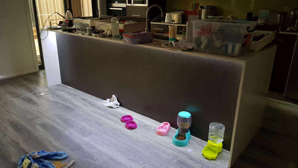
Thanks for your tips! I'll have to check those things on the next build, because I've had to pack everything up for now as I've been doing this on the kitchen table and I really need to keep my wife happy!
So for now I've installed the LED strip where I wanted it, which is under the kitchen breakfast bar. I plan to create the same setup elsewhere in the house and I'll try again to incorporate a motion sensor, and if I can get it to work I'll pull this setup down and try to fix it. For now though, I have at least achieved some of my goal. I'll post pictures below, but please excuse the mess as I took them before I cleaned up lol
-

Hello! It looks like you're interested in this conversation, but you don't have an account yet.
Getting fed up of having to scroll through the same posts each visit? When you register for an account, you'll always come back to exactly where you were before, and choose to be notified of new replies (either via email, or push notification). You'll also be able to save bookmarks and upvote posts to show your appreciation to other community members.
With your input, this post could be even better 💗
Register Login