Sensor board w/ liPo charger and fuel gauge +BMP180 +HTU21
-
@Anticimex You went all this way just to eliminate leaking? That is impressive. Are you going to implement this on your board or is this only a test? Did you also test the current leakage in voltage divider circuit connected all the time? What is the difference?
@ceech said:
@Anticimex You went all this way just to eliminate leaking? That is impressive. Are you going to implement this on your board or is this only a test? Did you also test the current leakage in voltage divider circuit connected all the time? What is the difference?
Well, it's not that complicated :)
No, I have not made any comparisons whatsoever. But I am pretty confident it will be less leaky than a voltage divider. That I simply won't use because the higher resistance you use, the more noise you get, which will in the end translate into a meaningless measurement. But I have not made any real-world measurements for comparison, as this is so use-case dependent. Also for a voltage divider, the current draw is small, and depending on the nodes power consumption, that current may, or may not, be negligible. -
Why not just use ordinary Alkaline AA batteries? Cheap, available everywhere in any store, excellent self-discharge etc. Couple that with a suitable voltage regulator (boost/step-up) that can start as low as 0.6-0.7V and you should be good to go even with a single AA/AAA.
-
Why not just use ordinary Alkaline AA batteries? Cheap, available everywhere in any store, excellent self-discharge etc. Couple that with a suitable voltage regulator (boost/step-up) that can start as low as 0.6-0.7V and you should be good to go even with a single AA/AAA.
@bjornhallberg the impression I get on the forum from people doing that is that they get roughly one month of lifetime of a charge. To me that is simply not good enough. Not by a long shot.
-
@bjornhallberg the impression I get on the forum from people doing that is that they get roughly one month of lifetime of a charge. To me that is simply not good enough. Not by a long shot.
@Anticimex I've run my sensors, including SR-501, DS18B20 and DHT22, on AA batteries for 4-6 months with little or no issues. And that is without a regulator. What happens eventually, with the DS18B20 for instance, is that the temp readings keep declining with the declining voltage. I'm actually very surprised that the SR-501 is still alive. The SR-501 sensor itself leaks like 50uA and I have a voltage divider to read the voltage (but I can't take the reading since the MQTT gateway doesn't seem to work). I read somewhere that that the SR-501 would produce massive false readings with the voltage drop but so far so good.
With a proper regulator you should be good for 1-2 years.
-
@Anticimex I've run my sensors, including SR-501, DS18B20 and DHT22, on AA batteries for 4-6 months with little or no issues. And that is without a regulator. What happens eventually, with the DS18B20 for instance, is that the temp readings keep declining with the declining voltage. I'm actually very surprised that the SR-501 is still alive. The SR-501 sensor itself leaks like 50uA and I have a voltage divider to read the voltage (but I can't take the reading since the MQTT gateway doesn't seem to work). I read somewhere that that the SR-501 would produce massive false readings with the voltage drop but so far so good.
With a proper regulator you should be good for 1-2 years.
@bjornhallberg Ok, well that sounds much more reasonable to me then :)
-
@Anticimex I've run my sensors, including SR-501, DS18B20 and DHT22, on AA batteries for 4-6 months with little or no issues. And that is without a regulator. What happens eventually, with the DS18B20 for instance, is that the temp readings keep declining with the declining voltage. I'm actually very surprised that the SR-501 is still alive. The SR-501 sensor itself leaks like 50uA and I have a voltage divider to read the voltage (but I can't take the reading since the MQTT gateway doesn't seem to work). I read somewhere that that the SR-501 would produce massive false readings with the voltage drop but so far so good.
With a proper regulator you should be good for 1-2 years.
@bjornhallberg Have you tried to compare regulated and non-regulated supply? It would be reasonable to assume you can get more out of the batteries if you can suck them down to 0.5-0.6V. But the step-up regulators are quite "leaky" so will that really translate to a longer runtime in the end? The regulator will be on even if the node is sleeping (and efficiency drops with current drop). So perhaps (depending on usage of course) a regulated supply will actually drain the batteries faster and the end result is that it causes shorter runtime even if more juice is pulled from the cells.
I have not yet set up a proper test environment for this myself.
I was considering having a regulator you could switch off. So that the Arduino itself runs unregulated but the sensors uses regulated power. Then you could turn off the regulator when sleeping. Like one of these.
A cool variant would be to have a regulator that turns itself on when battery voltage drops below a known safe level. The trick is to implement a power rail that can switch from unregulated to regulated supply. The switching can just be done with a comparator. But feedback between regulator output and input is a bad idea I suppose... -
@bjornhallberg Have you tried to compare regulated and non-regulated supply? It would be reasonable to assume you can get more out of the batteries if you can suck them down to 0.5-0.6V. But the step-up regulators are quite "leaky" so will that really translate to a longer runtime in the end? The regulator will be on even if the node is sleeping (and efficiency drops with current drop). So perhaps (depending on usage of course) a regulated supply will actually drain the batteries faster and the end result is that it causes shorter runtime even if more juice is pulled from the cells.
I have not yet set up a proper test environment for this myself.
I was considering having a regulator you could switch off. So that the Arduino itself runs unregulated but the sensors uses regulated power. Then you could turn off the regulator when sleeping. Like one of these.
A cool variant would be to have a regulator that turns itself on when battery voltage drops below a known safe level. The trick is to implement a power rail that can switch from unregulated to regulated supply. The switching can just be done with a comparator. But feedback between regulator output and input is a bad idea I suppose...@Anticimex Sorry, I don't have any long time data to offer. So I also don't know if bothering with the SHDN / EN pins (where applicable) is actually worth it. Quiescent current is usually pretty low on some of the better regulators (like TPS61221, LTC3525 etc) so I wonder if it is worth tampering with?
I still think you will gain a few months of run-time using a regulator. Still, no big savings there. The main reason (for me at least) to explore regulators is to enable sensors that would otherwise malfunction as the voltage drops. I.e. most of the common sensor we use (DHT22, DS18B20, Motion). Particularly the DS18B20 has been spotty for me.
Another point is to be able to build really compact sensors that use only one AA/AAA. Not even the nrf24 / atmega would work at 1.5V (and dropping) after all.
Also, according to my latest calculations, a separate pcb with the TPS61221 will cost about $1.75 in materials. So, it wont break the bank.
I wish we could fast-track the entire project a bit and come up with a standard form factor like LowPowerLabs or Harizanov where we could make shields that just plug. Btw, did you see this on the topic of LiPo batteries:
http://lowpowerlab.com/blog/2015/02/03/chinese-lithium-cells-freezing/ -
@bjornhallberg Have you tried to compare regulated and non-regulated supply? It would be reasonable to assume you can get more out of the batteries if you can suck them down to 0.5-0.6V. But the step-up regulators are quite "leaky" so will that really translate to a longer runtime in the end? The regulator will be on even if the node is sleeping (and efficiency drops with current drop). So perhaps (depending on usage of course) a regulated supply will actually drain the batteries faster and the end result is that it causes shorter runtime even if more juice is pulled from the cells.
I have not yet set up a proper test environment for this myself.
I was considering having a regulator you could switch off. So that the Arduino itself runs unregulated but the sensors uses regulated power. Then you could turn off the regulator when sleeping. Like one of these.
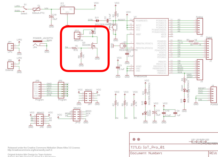
A cool variant would be to have a regulator that turns itself on when battery voltage drops below a known safe level. The trick is to implement a power rail that can switch from unregulated to regulated supply. The switching can just be done with a comparator. But feedback between regulator output and input is a bad idea I suppose...@Anticimex Just thinking out loud. Looking at the schematics of the predecessor of this board. There is a mosfet circuit connected to D4. Couldn't you use this to power up an external. regulator or step-up?
-
@Anticimex Just thinking out loud. Looking at the schematics of the predecessor of this board. There is a mosfet circuit connected to D4. Couldn't you use this to power up an external. regulator or step-up?
@AWI yea, but the problem is not activating the regulator. That is a simple IO operation. The problem I think is the output of the regulator, if you want it to power the Arduino itself. And you probably do, since the Arduino packs up probably before your sensors. I need to study some more before I got a plan for that, but I also have a LOT of other things to do so don't expect me to provide the One Solution to it in the coming weeks ;)
-
@AWI yea, but the problem is not activating the regulator. That is a simple IO operation. The problem I think is the output of the regulator, if you want it to power the Arduino itself. And you probably do, since the Arduino packs up probably before your sensors. I need to study some more before I got a plan for that, but I also have a LOT of other things to do so don't expect me to provide the One Solution to it in the coming weeks ;)
@Anticimex Switching the Arduino is probably not a good idea :) but powering up the voltage sensitive sensors with a mosfet switched step-up converter is an option?
-
@Anticimex Switching the Arduino is probably not a good idea :) but powering up the voltage sensitive sensors with a mosfet switched step-up converter is an option?
-
The main reason why I was dragged to the LTC4067 is the fact that it has so called Power path technology. It only uses the battery if there is no other available source of power. The benefit is much longer battery lifetime. It also has a proper 2A Lithium charger. Last but not least is the current monitoring, which can be translated into battery state of charge, which is another thing that interests me.
I chose the voltage regulator for the fact that is fairly efficient and powerful even for ESP8266 modules and as simple as possible to implement. It only uses 35uA, which is as low as I ever saw. And the LTC4067 has Suspend mode that only uses a couple of uA as well.
@tbowmo Prices for the HTU21 are lower, for me at least. And since the pinout is the same it is all for the better.
I'll put some thought into the separate power options. The first thing that can be fairly simply done is to power the Atmega328 from the battery, and the sensors from the regulator. -
Which is more useful - an EEPROM or Flash memory chip?
-
My vote is for flash memory, but no deal breaker
-
Finally managed to put all things together and made the first two test boards. They look like this:
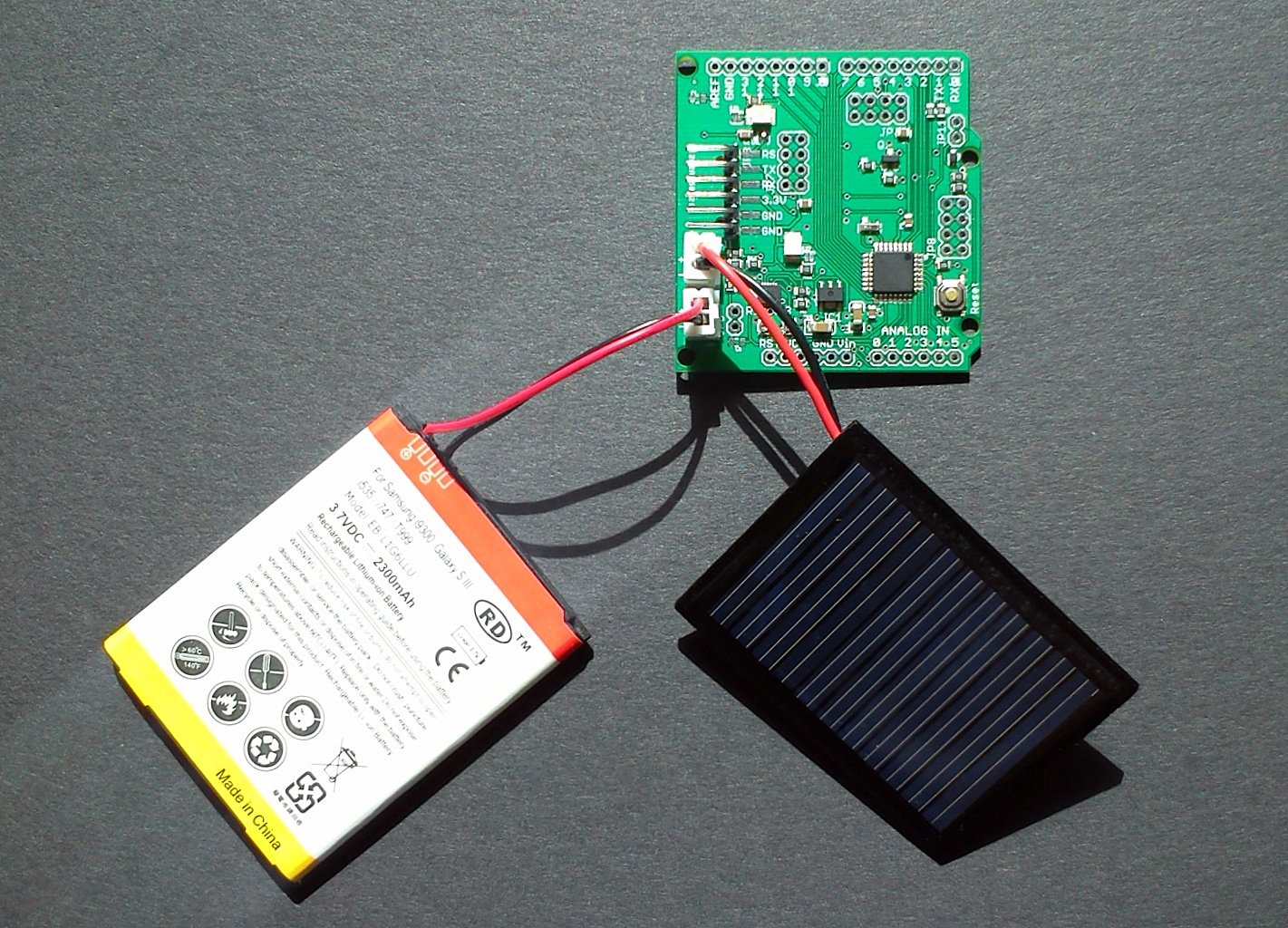
Main new features are LTC4067 lithium battery charger and XC6210, a low consumption voltage regulator.The board comes with a Torex XC6210 3.3V voltage regulator . It has low power consumption of 35μA, while delivering at least 700mA. Voltage drop is 50mV @ 100mA.
LTC4067 battery charger with Automatic Battery Charging/Load Switchover
It provides power for the circuit and charges the backup single-cell lithium battery while greatly extends battery life. You can monitor the voltages and currents. It has suspend mode, which reduces current consumption to around 40μA. The power source is a small, 5V solar cell. Connections:
analog input A1 on ATmega 328 is FAULT signal from LTC4067
analog input A0 on ATmega328 is battery voltage
analog input A2 is solar cell voltage
analog input A6 is input current ( I=V/R x 1000 )
analog input A7 is battery charge current ( I=V/R x 1000 )
digital output A9 - drive it high to put LTC4067 in SUSPEND modeThe two trimmer potentiometers are used to determine the current for both the input side - to better match the internal resistance of the solar cell - and for the battery charge current. At shipping they are both set to about 2.5kOhm, which set both currents to about 75mA. Please refer to technical data sheet of LTC4067 for more information. It is available here:
Official web page for LTC4067Or, ask me.
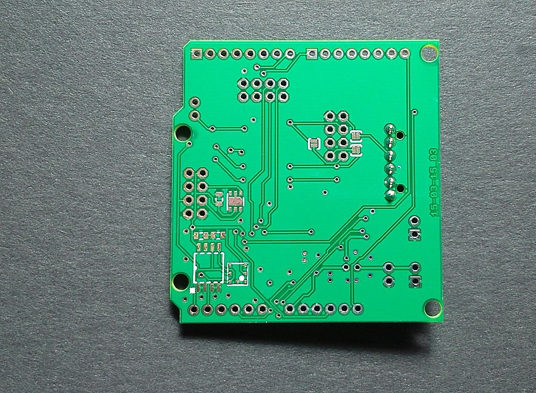
This is the back side of the board with place for BMP180, HTU21 and EEPROM chip:
-
@ceech , I recently bought one of the predecessor boards to this new design. I was wondering if you had a better feel yet on likely end user pricing for this new one? Do you plan on populating all active parts, or providing them for users to place themselves? Really looking forward to this board becoming available.
-
Finally managed to put all things together and made the first two test boards. They look like this:
Main new features are LTC4067 lithium battery charger and XC6210, a low consumption voltage regulator.The board comes with a Torex XC6210 3.3V voltage regulator . It has low power consumption of 35μA, while delivering at least 700mA. Voltage drop is 50mV @ 100mA.
LTC4067 battery charger with Automatic Battery Charging/Load Switchover
It provides power for the circuit and charges the backup single-cell lithium battery while greatly extends battery life. You can monitor the voltages and currents. It has suspend mode, which reduces current consumption to around 40μA. The power source is a small, 5V solar cell. Connections:
analog input A1 on ATmega 328 is FAULT signal from LTC4067
analog input A0 on ATmega328 is battery voltage
analog input A2 is solar cell voltage
analog input A6 is input current ( I=V/R x 1000 )
analog input A7 is battery charge current ( I=V/R x 1000 )
digital output A9 - drive it high to put LTC4067 in SUSPEND modeThe two trimmer potentiometers are used to determine the current for both the input side - to better match the internal resistance of the solar cell - and for the battery charge current. At shipping they are both set to about 2.5kOhm, which set both currents to about 75mA. Please refer to technical data sheet of LTC4067 for more information. It is available here:
Official web page for LTC4067Or, ask me.
This is the back side of the board with place for BMP180, HTU21 and EEPROM chip:
Hello! It looks like you're interested in this conversation, but you don't have an account yet.
Getting fed up of having to scroll through the same posts each visit? When you register for an account, you'll always come back to exactly where you were before, and choose to be notified of new replies (either via email, or push notification). You'll also be able to save bookmarks and upvote posts to show your appreciation to other community members.
With your input, this post could be even better 💗
Register Login