Piezzo siren/alarm

-
@mfalkvidd Something puzzling me here, can i please borrow your brain for a sec ?
@bjacobse mentionned that his small piezzo buzzer could take up to 30V...
So i had a go with my own buzzer and the previous schematic with 1S LiPo up to 6S LiPo (close to 25V) and 440Hz up to 32kHz (max Tone() )
No change there. Still the same noise i got with a smaller transistor and a 5V power supply.
Tone() changes the width of the modulation (X scale), so i get different tones.
Voltage of the power suppy changes the power going through the piezzo disc... but it doesn't get any louder.So what is the magic to get a loud buzzer? I shall get my oscilloscope within a month, so until then i keep scratching my head !!
@ben999
I guess you don't hit resonance frequency.
Why not scavenge a piezo from a smokealarm, then you you know that the circuit is made for resonance frequency.
BTW I did not write MY piezo is working at 30V, I directed to a piezo that Adafruit is using, and that uses up to 30V - just to correct that I hvae not used the pieo myself -
@bjacobse thanks for clarification :smile:
No smoke came out of mine under 25V DC so i guess it's ok
And yes, i shall cut open an old smoke alarm, you're right.
Thanks a lot
-
AFAIK the piezo acts like a capacitor. If you don't use AC, you may have to discharge it with a parallel resistor or discharge it with a transistor.
You could find some useful information on eevblog, e.g. http://www.eevblog.com/forum/projects/how-to-connect-a-piezo-speaker-to-a-microcontroller/
toneAC:
https://bitbucket.org/teckel12/arduino-toneac/wiki/Home -
AFAIK the piezo acts like a capacitor. If you don't use AC, you may have to discharge it with a parallel resistor or discharge it with a transistor.
You could find some useful information on eevblog, e.g. http://www.eevblog.com/forum/projects/how-to-connect-a-piezo-speaker-to-a-microcontroller/
toneAC:
https://bitbucket.org/teckel12/arduino-toneac/wiki/Home@fotofieber hi thank you for your message
I was coming back here to share my findings.... been playing with... ToneAC :joy:
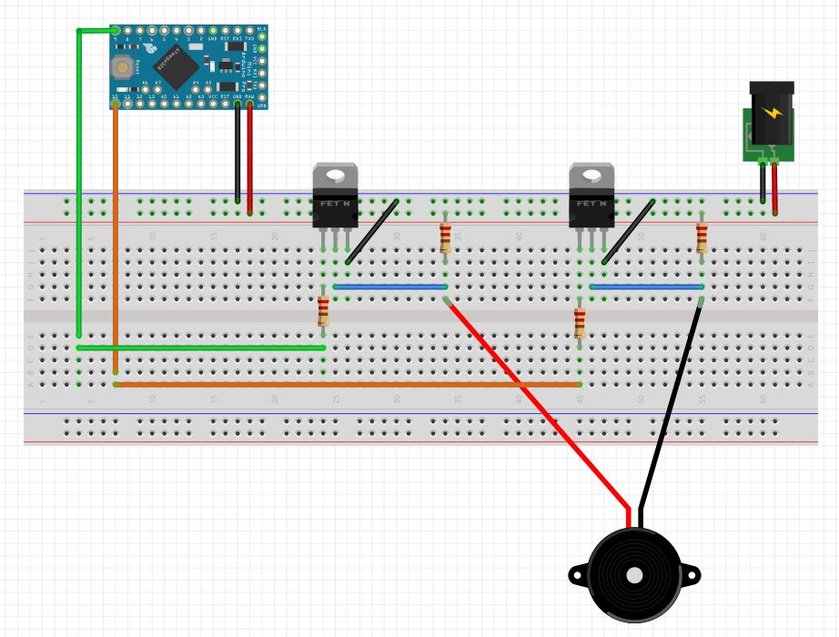
Yes you're right, differential drive makes a hell of a difference! each pin of the piezo speaker are connected to its own arduino output (serial resistor on one pin though) that send the same signal in opposition as to get a differential movment.
But i don't quite get it :
- driving the piezo speaker with up to 25V doesn't improve noise level at all
- switching to differential drive @5V (so it's a 10V potential peak-to-peak) opens hell's doors wide open
That's the part i dont understand. I'll carry on investigating.
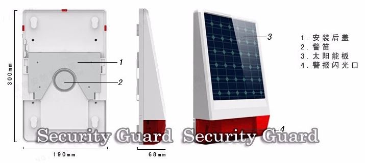
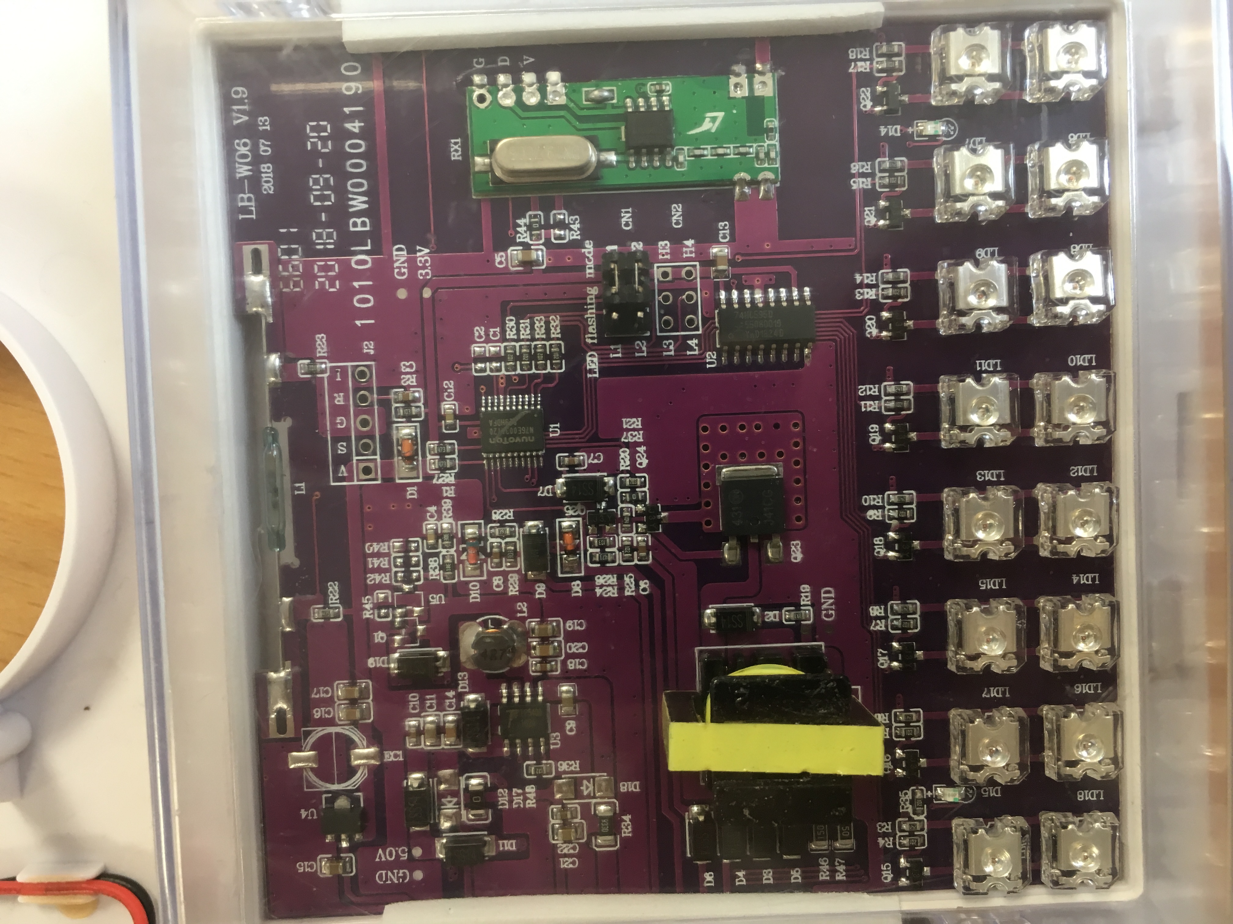
Still: noise level is a bit below as compared to same pizeo speaker connected to original alarm enclosure...
I might have a go with transistors and try a differential of 2S or 3S LiPo.
Also waiting for my oscilloscope to find out!And lastly: ToneAC uses pins 9 and 10... so it's a NO-NO with nRF24 :cry:
Enters... ToneAC2. It's inferior (CPU cycle, accuracy, lower freq) in many points except that pins are configurable.More soon... :nerd_face:
-
@fotofieber hi thank you for your message
I was coming back here to share my findings.... been playing with... ToneAC :joy:
Yes you're right, differential drive makes a hell of a difference! each pin of the piezo speaker are connected to its own arduino output (serial resistor on one pin though) that send the same signal in opposition as to get a differential movment.
But i don't quite get it :
- driving the piezo speaker with up to 25V doesn't improve noise level at all
- switching to differential drive @5V (so it's a 10V potential peak-to-peak) opens hell's doors wide open
That's the part i dont understand. I'll carry on investigating.
Still: noise level is a bit below as compared to same pizeo speaker connected to original alarm enclosure...
I might have a go with transistors and try a differential of 2S or 3S LiPo.
Also waiting for my oscilloscope to find out!And lastly: ToneAC uses pins 9 and 10... so it's a NO-NO with nRF24 :cry:
Enters... ToneAC2. It's inferior (CPU cycle, accuracy, lower freq) in many points except that pins are configurable.More soon... :nerd_face:
@ben999 said in Piezzo siren/alarm:
But i don't quite get it :
driving the piezo speaker with up to 25V doesn't improve noise level at all
switching to differential drive @5V (so it's a 10V potential peak-to-peak) opens hell's doors wide openYou may try to use a 1kOhm resistor parallel to the piezo (as suggested on eevblog).
-
@ben999 nice work, thanks for sharing.
To change pins for the nrf24, use the following in your sketch
#define MY_RF24_CE_PIN 7 #define MY_RF24_CS_PIN 8@mfalkvidd oh yeah I forgot about that one!!! Thanks a lot! I have used this with a Mega for who-knows-what-reason in the past but completely forgot about it! ToneAC still in the race then, thanks again
@fotofieber thanks a lot, but that thread is for high-level hobbyists!!! :scream: Schematics, yummy!!!
"replace the resistor with an inductor then you double the swing" but no figures... i'll google that and see where it gets me...
I dont even know the specs of my piezo :zipper_mouth_face: -
@mfalkvidd oh yeah I forgot about that one!!! Thanks a lot! I have used this with a Mega for who-knows-what-reason in the past but completely forgot about it! ToneAC still in the race then, thanks again
@fotofieber thanks a lot, but that thread is for high-level hobbyists!!! :scream: Schematics, yummy!!!
"replace the resistor with an inductor then you double the swing" but no figures... i'll google that and see where it gets me...
I dont even know the specs of my piezo :zipper_mouth_face:@ben999 said in Piezzo siren/alarm:
@fotofieber thanks a lot, but that thread is for high-level hobbyists!!! Schematics, yummy!!!
"replace the resistor with an inductor then you double the swing" but no figures... i'll google that and see where it gets me...
I dont even know the specs of my piezoI try to simplify: Take a 1 kOhm resistor and attach each side of it to another pin of the piezo. Don't change anything else.
-
@ben999 said in Piezzo siren/alarm:
@fotofieber thanks a lot, but that thread is for high-level hobbyists!!! Schematics, yummy!!!
"replace the resistor with an inductor then you double the swing" but no figures... i'll google that and see where it gets me...
I dont even know the specs of my piezoI try to simplify: Take a 1 kOhm resistor and attach each side of it to another pin of the piezo. Don't change anything else.
@fotofieber :grin: oh yes i got that one correct :stuck_out_tongue_winking_eye:
It was more about how to size the inductor and stuff. Guys on these forums know their sh*t, they dont go into much details: "just stick a thing there and you'll be good" :joy:
-
Guys,
Thanks all a lot for your input.
Seems sorted :
- differential drive (ToneAC)
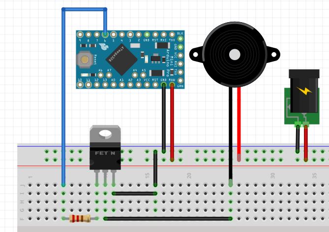
- transistor (TIP120 in my case, not sure it's my best move)
- 3S louder than 2S, itself louder than 1S
Schematic TIP120 and 1k resistors
I did also put a 1k resistor in between the piezo speaker pins... but it lowered the tone by quite a lot... :thinking_face:To be tested
I'll have a go with an inductance to see what " then you double the swing" means... double the loudness or double the speed ?
Thanks again, people involved :wink:
-
Guys,
Thanks all a lot for your input.
Seems sorted :
- differential drive (ToneAC)
- transistor (TIP120 in my case, not sure it's my best move)
- 3S louder than 2S, itself louder than 1S
Schematic TIP120 and 1k resistors
I did also put a 1k resistor in between the piezo speaker pins... but it lowered the tone by quite a lot... :thinking_face:To be tested
I'll have a go with an inductance to see what " then you double the swing" means... double the loudness or double the speed ?
Thanks again, people involved :wink:
@ben999 said in Piezzo siren/alarm:
I did also put a 1k resistor in between the piezo speaker pins... but it lowered the tone by quite a lot..
Cool, you sorted it out! The resistor may only help in an DC setup (one output from the arduino). In your AC setup it is useless.
-
@ben999 said in Piezzo siren/alarm:
I did also put a 1k resistor in between the piezo speaker pins... but it lowered the tone by quite a lot..
Cool, you sorted it out! The resistor may only help in an DC setup (one output from the arduino). In your AC setup it is useless.
@fotofieber gosh that a good analysis :+1: that makes a lot of sense
Then i can picture things better:- one output with 0 et +5V is considered as DC
- two output pulling differentially -5V to +5V... looks like a sin curbe... so it's AC !
Breadboard is out and still cabled, i'll have a go asap and confirm
Thanks again for your knowledge
-
@fotofieber gosh that a good analysis :+1: that makes a lot of sense
Then i can picture things better:- one output with 0 et +5V is considered as DC
- two output pulling differentially -5V to +5V... looks like a sin curbe... so it's AC !
Breadboard is out and still cabled, i'll have a go asap and confirm
Thanks again for your knowledge
@ben999
You could try DC (one output) with 12V to the piezo. If you want to use only 5V, the AC solution should be louder, as it gets 10V difference to the piezo.I usually stop optimizing, when it is good enough. If AC is enough, go with it. :)
-
@ben999
You could try DC (one output) with 12V to the piezo. If you want to use only 5V, the AC solution should be louder, as it gets 10V difference to the piezo.I usually stop optimizing, when it is good enough. If AC is enough, go with it. :)
@fotofieber DC+ one output is really poor and voltage has no impact on noise. I have tested with up to 6S LiPo and there's absolutely no gain as compared to 5V DC
AC+ two outputs is a game changer! Much louder right from +/-5V and really a killer @ +/-12V.
So that's it: the first iteration of this project will go for a step-up converter from 5V up to 12V for the piezo speaker.
Thanks folks!
EDIT: could someone suggest a MOSFET (or transistor) that could be used in lieu of the huge (and probably over-sized) TIP120 (that where there, waiting in the drawer :) ). Through-hole is my league. SMD is a bit of a struggle (welding, machining pcb, ...)
Thanks again :smiley: