RF Nano = Nano + NRF24, for just $3,50 on Aliexpress
-
-
@martim Just search for RF Nano on Aliexpress. Haven't looked for the cheapest one, just the first that says LRF24L01+. Although not certain if it is really a + version of the NRF24L01.
-
@martim I think this is a better alternative: https://www.electrodragon.com/product/nrf24duino-arduino-mini-plus-nrf24l01-board/
-
@martim I think this is a better alternative: https://www.electrodragon.com/product/nrf24duino-arduino-mini-plus-nrf24l01-board/
@ncollins That is a nice board indeed. I haven't checked because I will order some things after dinner. For me it is a must to keep the arduino Nano footprint. So I can replace the nano and nrf in some of the projects I already built.
-
@ncollins That is a nice board indeed. I haven't checked because I will order some things after dinner. For me it is a must to keep the arduino Nano footprint. So I can replace the nano and nrf in some of the projects I already built.
-
@martim I think this is a better alternative: https://www.electrodragon.com/product/nrf24duino-arduino-mini-plus-nrf24l01-board/
-
@martim Yep, you just need to make sure to turn off the EEPROM module after setup, then it's basically an Atmega328p and NRF24L01+. It has solderable jumpers to bypass the voltage regulator and status LED.
Here is a claim of 12uA in sleep: https://forum.mysensors.org/post/96631
-
Why not go for a sensebender? https://www.itead.cc/mysensors-micro.html
I have one in each room, measuring temp and humidity. It works great
-
Why not go for a sensebender? https://www.itead.cc/mysensors-micro.html
I have one in each room, measuring temp and humidity. It works great
-
@martim Yep, you just need to make sure to turn off the EEPROM module after setup, then it's basically an Atmega328p and NRF24L01+. It has solderable jumpers to bypass the voltage regulator and status LED.
Here is a claim of 12uA in sleep: https://forum.mysensors.org/post/96631
-
@martim said in RF Nano = Nano + NRF24, for just $3,50 on Aliexpress:
@TheoL way to expensive.
For less money, and very little effort, you can put your own together: https://www.openhardware.io/view/480/Compact-nRF24L01-Pro-Mini-Bottom-Shield
As demonstrated, it also gives you more choice and control over the type/quality of nRF24 module that you get.
-
I know it's an old topic. But Today I received 2 of the Makefun RF Nanos. And after reading this topic I feared I would need a lot of time to get it to work. But I quickly adjusted a MySensors example and hooked a led to it, just to able to test.
I don't need to specify the CE and CS pins - in fact it didn't work if I did. And I can control the led with the node located in every room in my house. Not that I have a very big house. But so far no failures. So the reach isn't that bad at all. I also see a connector that seems to be there for hooking up an Antenna. I think that would be something I try before replacing the capacitor.
As a non hardware specialist soldering SMD is a skill I have yet to master. So I'm quite happy with the small footprint. As I don't plan on powering this one with batteries, I power it with a phone charger. Next step is to see how stable it is as a gateway. But That is something I wanna try in the weekend.
Here's the simple sketch I used. Don't watch the comments. I literally heked it together to be able to test it.
 Test sketch for testing the RF Nano
*/

// Enable debug prints to serial monitor
//#define MY_DEBUG

// Enable and select radio type attached
#define MY_RADIO_NRF24
//#define MY_RADIO_RFM69

#include <SPI.h>
#include <MySensors.h>

#define SN "RF Nano test"
#define SV "1.0"

const uint8_t LED_PIN = 8;

MyMessage lightMsg(0, V_LIGHT);


/***
   Test sketch initialization method
*/
void setup()
{
  pinMode( LED_PIN, OUTPUT );
  digitalWrite( LED_PIN, LOW );

}

void presentation() {
  // Register the LED Dimmable Light with the gateway
  present( 0, S_LIGHT );

  delay( 50 );

  sendSketchInfo(SN, SV);

  delay( 50 );

  // Pull the gateway's current light state  upon sensor node power-up. All examples says it should be in the setup -
  // but that never works for me. Besides I thought the setup was only executed ones and the presentation each time after a succesfull connection
  request( 0, V_LIGHT );
}

/***
    Dimmable LED main processing loop
*/
void loop()
{
}

void receive(const MyMessage &message) {
  if (message.type == V_LIGHT || message.type == V_DIMMER) {
    Serial.println( message.data  );
    int lightState = atoi( message.data );

    if ( lightState ) {
      Serial.println( "Turning light on" );
      digitalWrite( LED_PIN, HIGH );
    }
    else {
      Serial.println( "Turning light off" );
      digitalWrite( LED_PIN, LOW );
    }
So far happy with it. I'll give it a durability test the next few weeks. Just to see if it will keep working. The only thing I really don't like is the very very bright power led. So I guess I have to start practicing removing these tiny SMD leds.
But if it keeps performing as it does. This might be my to go with board for all non battery powered nodes.
@TheoL
Thanks for reporting back! There's no better way to know than by trying it, as you are.These days wireless is so inexpensive that--dare I say it?--I wish it was standard issue, with the same kind of presumption that puts an LDO on all the pro mini's, including even the dirt cheap pro mini's. That way, driven by economies of scale, it becomes almost free. All it takes is a sparkfun or an adafruit to issue a design and then soon after China steps in and makes it happen.
-
So I know a lot of people switched over to Tasmota and other ESP enabled solution. Just wanted to share my experience of Today and couldn't really find another topic.
As of Today I finally have fiber glass internet. Something I looked forward to and feared at the same time. I was looking forward to the speed. But not in getting everything working with a new router. I'll keep it short.
- Telephone - worked immediately no problems at all
- Wifi - Hard time finding the new ssid. But I lucked out. After a call with KPN, I found out the new router copied the ssid and password from the old router
- Getting home automation and Ikea tradfri gateway running. I use TP-link power line to connect all ethernet devices by wire. But I always assumed you couldn't use a switch connected to a tp-link. Oh boy I was wrong. It worked.
- The new router differs from the old one, in the way that it does not have a separate output for the tv receiver, you can connect the receiver just to any ethernet port you have available. So I hooked the reciever up to a tp-link and running.
- Sonos didn't work. I needed to connect only one with ethernet to my router en reenter the SSID and passwd. But then Sonos was back in the air.
Now imagine of you have a dozen of ESP as sensors or actuators. And the new router would not have copied the SSID and password? Then I would manually have to set the new ssid and password for each ESP. When I realized this, it came to me how simple MySensors is in use. Thankful that I discovered it. And thankful to you all for creating this great sensors network
-
Hello,
I use the RF-NANO widely in my sensors. At the beginning of the year I reordered 10 pcs and I got the new version.
I discovered that between V1 (bought in 2019) and V2 (bought in 2020) D9 and D10 are reversed between the 2 versions.V1
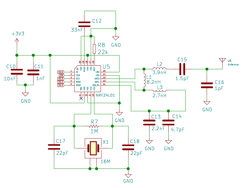
V2
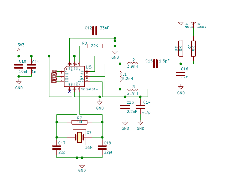
links:
https://github.com/emakefun/emakefun-nano-plus/blob/master/RF-Nano/Schematic/RF-Nano-Schematic.pdf
https://github.com/emakefun/rf-nano/blob/master/RF-Nano-Schematic.pdfHope it helps.
Franco -
How ever powering from usb is not very stable. When sending multiple messages with delays my sketch sometimes stalls. Need to test with the suggested 6v power supply though. But most nodes don't need to send multiple messages quickly