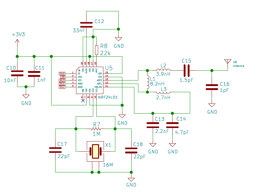
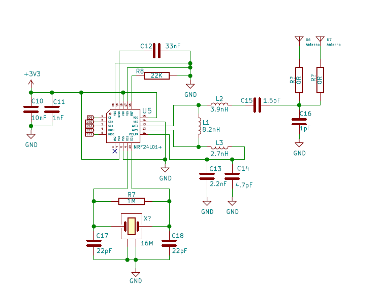
RF Nano = Nano + NRF24, for just $3,50 on Aliexpress


  • Plugin Developer

    And here's a similar issue. https://forum.mysensors.org/topic/8190/rf24-rbr-reg-23-val-17

    After some testing I can say that just setting #define MY_DEBUG_VERBOSE_RF24 completely solves the issue.

    The node now works.

    Never give up, never surrender!


  • I've ordered three of them and tried to get them working. But when I reproduce your configuration, the debug messages show me that it's not possible to establish a connection to the RF24 module.

    Here is my configuration

    // Enable debug prints to serial monitor
    #define MY_DEBUG
    #define MY_DEBUG_VERBOSE_RF24
    
    // Enable and select radio type attached
    #define MY_RADIO_RF24
    
    // PINS for the RF24 Communication
    #define MY_RF24_CE_PIN 10 
    #define MY_RF24_CS_PIN 9
    
    // Add some wait time until network is ready on node startup
    #define MY_TRANSPORT_WAIT_READY_MS 1000
    
    // Enable AES encryption
    #define MY_RF24_ENABLE_ENCRYPTION
    
    // Enable message signing
    #define MY_SIGNING_SOFT
    // Not longer required since the CPU integrated random numger generator is used
    //#define MY_SIGNING_SOFT_RANDOMSEED_PIN A0
    #define MY_VERIFICATION_TIMEOUT_MS 5000
    #define MY_SIGNING_REQUEST_SIGNATURES
    #define MY_SIGNING_GW_REQUEST_SIGNATURES_FROM_ALL
    

    this are the log statements:

     __  __       ____
    |  \/  |_   _/ ___|  ___ _ __  ___  ___  _ __ ___
    | |\/| | | | \___ \ / _ \ `_ \/ __|/ _ \| `__/ __|
    | |  | | |_| |___| |  __/ | | \__ \  _  | |  \__ \
    |_|  |_|\__, |____/ \___|_| |_|___/\___/|_|  |___/
            |___/                      2.3.1
    
    16 MCO:BGN:INIT NODE,CP=RNNNAS-X,REL=255,VER=2.3.1
    65 TSM:INIT
    66 TSF:WUR:MS=1000
    68 RF24:INIT
    69 RF24:INIT:PIN,CE=10,CS=9
    71 RF24:SBY
    72 RF24:WBR:REG=0,VAL=14
    79 RF24:WBR:REG=3,VAL=3
    81 RF24:WBR:REG=4,VAL=95
    83 RF24:WBR:REG=5,VAL=76
    87 RF24:WBR:REG=6,VAL=37
    89 RF24:WBR:REG=29,VAL=4
    91 RF24:RBR:REG=29,VAL=4
    93 RF24:RBR:REG=6,VAL=5
    95 !RF24:INIT:SANCHK FAIL
    98 !TSM:INIT:TSP FAIL
    99 TSM:FAIL:CNT=1
    101 TSM:FAIL:DIS
    103 TSF:TDI:TSL
    104 RF24:SLP
    105 RF24:WBR:REG=0,VAL=12
    1067 MCO:BGN:STP
    1068 !TSF:SND:TNR
    1070 !TSF:SND:TNR
    

    Currently I power the whole thing just trough the connected USB device. Is it possible that RF24 doesn't get powered through USB and has to be powered externally...? I tried different configurations and none of them got the RF24 working.


  • Mod

    @sbrinkmann said in RF Nano = Nano + NRF24, for just $3,50 on Aliexpress:

    87 RF24:WBR:REG=6,VAL=37
    89 RF24:WBR:REG=29,VAL=4
    91 RF24:RBR:REG=29,VAL=4
    93 RF24:RBR:REG=6,VAL=5
    95 !RF24:INIT:SANCHK FAIL
    98 !TSM:INIT:TSP FAIL

    The nRF24 sanity check fails, which compares the RF setup & RF channel registers to the configured values:
    https://github.com/mysensors/MySensors/blob/development/hal/transport/RF24/driver/RF24.cpp#L387

    The setup value should be 37 (0b‭00100101‬), but is read as 5 (0b00000101) (--> bit number 5 isn't set)

    From the nRF24 datasheet:
    0_1557645231611_0858a898-2fe0-4530-8c9c-f38465495b57-image.png

    Bit 5 is RF_DR_LOW, which is used to set the datarate at 250kbps.

    Concluding: the 'nRF24L01+' on the board isn't a genuine nRF24L01+ but some clone/compatible/different type/... (hi-res picture of the nRF24 package please 😉 )
    You could give it a try with 1MBps and see if that works with the MySensors stack.


  • Plugin Developer

    @sbrinkmann I ordered two, and with one of them I also couldn't even connect to the radio. I thought that was just a dud, but reading that all three of yours don't work, that may not have been the case.


  • maybe also try just loading up a simple sketch with RF24 lib, and dump out RF24::printDetails() to see what the chip identifies as.
    I have an older device with genuine NRF24L01 (not plus), which it correctly identifies.
    http://tmrh20.github.io/RF24/classRF24.html#adc95213ed4c8569a90eb33122e16cea6
    Might also be some strange clone behavior like yveaux mentioned.
    Also, are you sure the nrf is getting 3.3vdc? I have seen some strange behavior when I powered a 3v3 mini input with 4.2v lipo, where the nrf24 would seem to initialize but not really work with mysensors. (This exceeded the 3.6v Vin max, but somehow after reducing the voltage back to normal operating levels, i.e. 3.3v, the nrf24 seemed fine again.)


  • Plugin Developer

    @jens-jensen Could you share a printDetails example sketch?


  • Finally got my 2 working but at a sacrifice! they will only work at 1mbps or 2mbps.
    i setup an esp8266 as a gateway and had to add:
    #define MY_RF24_DATARATE RF24_1MBPS

    Here is the addional code i used on th rf-nano sketch;
    #define MY_RF24_CE_PIN 10
    #define MY_RF24_CS_PIN 9
    // #define MY_RF24_DATARATE RF24_250KBPS
    #define MY_RF24_DATARATE RF24_1MBPS

    Its a shame they wont work on 250kbps as i need the distance for a project i am playing with. oh well.
    Hope my findings help someone.


  • Mod

    @david-abbott nice work.

    Maybe the nrf is a nrf24l01 (without + at the end)? They only support 1 and 2 mbit, not 250kbps.


  • Plugin Developer

    @David-Abbott My 'dead' node now works as well! Thank you!

    I can even leave out the #define MY_DEBUG_VERBOSE_RF24.

    What is your experience in the difference in range between 250Kbps and 1mbps?


  • Hardware Contributor

    @alowhum said in RF Nano = Nano + NRF24, for just $3,50 on Aliexpress:
    @alowhum said in RF Nano = Nano + NRF24, for just $3,50 on Aliexpress:

    Funnily enough, enabling the #define MY_DEBUG_VERBOSE_RF24 feature means it actually connects on MySensors version 2.3.1.

    @David-Abbott My 'dead' node now works as well! Thank you!

    I can even leave out the #define MY_DEBUG_VERBOSE_RF24.

    That's exactly what I meant to you in your other post about wait().. easy to interpret results and makes wrong assumption 😉
    in practice I often noted people having comm issues when I didn't have one, with my custom hardware. Carefully sourced parts, no out of specs crystal quartz or counterfeits ics etc, so many details when buying cheap hw from ali (or even from some makers too), I could make a checklist. Wondering why not supporting counterfeits for 328p too, for fun of maintenance 😬

    great to hear you found a solution for your boards 👍


  • Plugin Developer

    @scalz You're kinda right, but not 100%.

    I have two of the boards. The one I thought was broken (radio would not even init) does now work, and works totally fine.

    The other device actually worked without having to set the datarate to 1Mbps, but only if I enabled the verbose debug. It now also works without the verbose debug.. but only on the third attempt to connect to the gateway. For the first 20 seconds it will just give FPAR NO REPLY. Then, somehow, it starts to connect.

    For this node, if I add the verbose debug line it connects right away. So there's still something going on where adding the verbose option improves how the radio functions. And of course I wasn't the first to have this strange issue.

    I get your point about not wanting to support counterfeit radio modules. But on the other hand, there are a lot of them out there, and supporting them could also just be a case of accepting the messiness that is reality. If a small delay (or whatever it is that the verbose debug does) can make a lot of cheap modules work, is it really that bad of an idea to add something like that as an option?


  • Hardware Contributor

    @alowhum said in RF Nano = Nano + NRF24, for just $3,50 on Aliexpress:

    For this node, if I add the verbose debug line it connects right away. So there's still something going on where adding the verbose option improves how the radio functions. And of course I wasn't the first to have this strange issue.

    I get your point about not wanting to support counterfeit radio modules. But on the other hand, there are a lot of them out there, and supporting them could also just be a case of accepting the messiness that is reality. If a small delay (or whatever it is that the verbose debug does) can make a lot of cheap modules work, is it really that bad of an idea to add something like that as an option?

    Well it's still some funky behaviour from the radio, when using a non-related option or random delays are able to activate some kind of "black magic" inside the radio module to make it run (somehow) as expected.
    There's already some support for fake radio modules in MySensors I think, @scalz was talking about support for fake 328p that seem to be used sometimes, like the LGT8f used in defunct Wemos XI and LGT Nano.


  • @mfalkvidd I just checked it under a microscope and you are wright, it's a nrf24L01 without the "+". I just desoldered the nrf24L01 off the RF-Nano board and put a nrf24L01+ in place and now it works also on 250kbps.


  • very interesting thread to read to understand all those bloody counterfeit HW
    and also how you managed to find out - and good that Mysensors sw provide a good logfile for investigating


  • Plugin Developer

    @bjacobse Indeed, MySensors rocks.

    I've ordered 10 more for a workshop, and they arrived in about a week! They come in boxes of 5. I've tested a few, and they all work.


  • How are people getting on with these boards, mine just arrived today so doing a bit of testing. I wanted one as a replacement gateway for home assistant. I've got it working at 1mb and the pin changes suggested above, just wondered how they worked out for people in practice over the long term.

    I also wanted to mention that there is another option although it would work out more expensive

    https://www.aliexpress.com/item/Keywish-Nano-Terminal-Expansion-Adapter-Board-for-Arduino-Nano-V3-0-AVR-ATMEGA328P-with-NRF2401-Expansion/32957033159.html?spm=a2g0s.9042311.0.0.6df84c4dcMws6c


  • Plugin Developer

    @chickey said in RF Nano = Nano + NRF24, for just $3,50 on Aliexpress:

    https://www.aliexpress.com/item/Keywish-Nano-Terminal-Expansion-Adapter-Board-for-Arduino-Nano-V3-0-AVR-ATMEGA328P-with-NRF2401-Expansion/32957033159.html?spm=a2g0s.9042311.0.0.6df84c4dcMws6c

    That expansion board does not contain a Nano itself. It's just an expansion, in the same style at the existing Nano Wireless Boards? I prefer those, since they have Dupont pins, including a GND and VCC pin for every digital and analog pin. (But these are not compatible with the RF Nano). Those are $1.5.

    The RF Nano's are doing fine over here. I'm waiting for 10 normal $1 expansion boards to arrive.


  • Attention!!! These modules are equipped with radio chips nrf24l01 (without +)...do not operate at 250kbit speed


  • Plugin Developer

    We know 🙂

    I just bought 70 the other day, they are so useful for workshops. And since you can use them at maximum power their range is acceptable too.


  • Just got 4 of these, happy to say they're all '+' models and connect without issues, bingo!


  • @mark-swift Do you have a link of your supplier?


  • I previously purchased from the exact product link listed by @Mark-Swift and confirmed they are not + models.


  • @dustin-thurston Mine are certainly plus models, as they connect at 250kbps without issue (nor do they need debug turned on).


  • Can others report their luck? I hate to purchase again and get same result. Especially when seller was non-responsive.


  • Hi ! Got a couple of these. Hard to say if its + chip ( but I guess not ). Anyway I am not able to get them running a simple test sketch. Only get RBR:REG=23, VAL=17


  • @torfinn
    i had to set
    #define MY_RF24_CE_PIN 10
    #define MY_RF24_CS_PIN 9
    on mine (definetly not + btw) a while back....


  • I just got my order of 3, this time I got the nRF24L01+ version.


  • Plugin Developer

    😄 Now I wish I hadn't bought 70 of the old version already.

    They're working well though, very happy with them. Great for workshops.


  • @zen85 Thanks I got it to work but if I add #define MY_DEBUG_VERBOSE_RF24 i still get RBR:REG=23, VAL=17 filling the console....


  • Banned

    This post is deleted!

  • Plugin Developer

    @torfinn These settings should make it work, regardless of which version you buy:

    // If you are using an RF-Nano, you have to switch CE and CS pins.
    #define MY_RF24_CS_PIN 9                            // Used by the MySensors library.
    #define MY_RF24_CE_PIN 10                           // Used by the MySensors library.
    
    // Enable and select radio type attached
    #define MY_RADIO_RF24
    #define MY_RF24_PA_LEVEL RF24_PA_MAX
    
    // Mysensors advanced settings
    #define MY_RF24_DATARATE RF24_1MBPS                 // This datarate is supported by pretty much all NRF24 radios, including the RF-Nano.


  • Hi guys
    just a newbie in MySensors, i am buikding my home net with RF24 radio.
    Just received 4 of this rf-nano (+ chip) and set one into relay device
    With my Wemos D1mini pro + NRF24L01 +PA+LA gateway, it works in my whole (relatively large) house (approx 30m through a lot of walls and armed floor).
    Really handy for small boxes projects, the missing functionality is the interrupt pin not (easily ?) accessible for battery powering


  • I continue my test with this chip, and solved an issue in declaring children of a node

    I tried the relay actuator with 2 relays, the second one never wanted to get an ACK message for the presentation message
    I tried with 3 children relays , first is ACK, second still NACK and 3rd .... ACK again !

    Even if it was not my first thought, i finally insert a wait(1000) between each present line which solved the problem

    hope it can help


  • You might be interested by the board I've designed. Not "RF Nano" but "RF Pro Mini". Of course you need a "USB to serial" programmer but it directly runs on batteries.
    See here and here.


  • @echi Where could you order this board?


  • Contest Winner

    @martim Just search for RF Nano on Aliexpress. Haven't looked for the cheapest one, just the first that says LRF24L01+. Although not certain if it is really a + version of the NRF24L01.

    This is one on Aliexpress


  • Contest Winner

    @ncollins That is a nice board indeed. I haven't checked because I will order some things after dinner. For me it is a must to keep the arduino Nano footprint. So I can replace the nano and nrf in some of the projects I already built.


  • @TheoL I meant the board of @echi here as I need battery power board and this seems to be working well.


  • @ncollins If this board is suitable for battery use? I don't see how much current it uses.


  • @martim Yep, you just need to make sure to turn off the EEPROM module after setup, then it's basically an Atmega328p and NRF24L01+. It has solderable jumpers to bypass the voltage regulator and status LED.

    Here is a claim of 12uA in sleep: https://forum.mysensors.org/post/96631


  • Contest Winner

    Why not go for a sensebender? https://www.itead.cc/mysensors-micro.html

    I have one in each room, measuring temp and humidity. It works great


  • @TheoL way to expensive.


  • @ncollins okay, give it a try.


  • Hero Member

    @martim said in RF Nano = Nano + NRF24, for just $3,50 on Aliexpress:

    @TheoL way to expensive.

    For less money, and very little effort, you can put your own together: https://www.openhardware.io/view/480/Compact-nRF24L01-Pro-Mini-Bottom-Shield

    As demonstrated, it also gives you more choice and control over the type/quality of nRF24 module that you get.


  • Contest Winner

    I know it's an old topic. But Today I received 2 of the Makefun RF Nanos. And after reading this topic I feared I would need a lot of time to get it to work. But I quickly adjusted a MySensors example and hooked a led to it, just to able to test.

    I don't need to specify the CE and CS pins - in fact it didn't work if I did. And I can control the led with the node located in every room in my house. Not that I have a very big house. But so far no failures. So the reach isn't that bad at all. I also see a connector that seems to be there for hooking up an Antenna. I think that would be something I try before replacing the capacitor.

    As a non hardware specialist soldering SMD is a skill I have yet to master. So I'm quite happy with the small footprint. As I don't plan on powering this one with batteries, I power it with a phone charger. Next step is to see how stable it is as a gateway. But That is something I wanna try in the weekend.

    Here's the simple sketch I used. Don't watch the comments. I literally heked it together to be able to test it.

     Test sketch for testing the RF Nano
    */
    
    // Enable debug prints to serial monitor
    //#define MY_DEBUG
    
    // Enable and select radio type attached
    #define MY_RADIO_NRF24
    //#define MY_RADIO_RFM69
    
    #include <SPI.h>
    #include <MySensors.h>
    
    #define SN "RF Nano test"
    #define SV "1.0"
    
    const uint8_t LED_PIN = 8;
    
    MyMessage lightMsg(0, V_LIGHT);
    
    
    /***
       Test sketch initialization method
    */
    void setup()
    {
      pinMode( LED_PIN, OUTPUT );
      digitalWrite( LED_PIN, LOW );
    
    }
    
    void presentation() {
      // Register the LED Dimmable Light with the gateway
      present( 0, S_LIGHT );
    
      delay( 50 );
    
      sendSketchInfo(SN, SV);
    
      delay( 50 );
    
      // Pull the gateway's current light state  upon sensor node power-up. All examples says it should be in the setup -
      // but that never works for me. Besides I thought the setup was only executed ones and the presentation each time after a succesfull connection
      request( 0, V_LIGHT );
    }
    
    /***
        Dimmable LED main processing loop
    */
    void loop()
    {
    }
    
    void receive(const MyMessage &message) {
      if (message.type == V_LIGHT || message.type == V_DIMMER) {
        Serial.println( message.data  );
        int lightState = atoi( message.data );
    
        if ( lightState ) {
          Serial.println( "Turning light on" );
          digitalWrite( LED_PIN, HIGH );
        }
        else {
          Serial.println( "Turning light off" );
          digitalWrite( LED_PIN, LOW );
        }
    

    So far happy with it. I'll give it a durability test the next few weeks. Just to see if it will keep working. The only thing I really don't like is the very very bright power led. So I guess I have to start practicing removing these tiny SMD leds.

    But if it keeps performing as it does. This might be my to go with board for all non battery powered nodes.


  • Hero Member

    @TheoL
    Thanks for reporting back! There's no better way to know than by trying it, as you are.

    These days wireless is so inexpensive that--dare I say it?--I wish it was standard issue, with the same kind of presumption that puts an LDO on all the pro mini's, including even the dirt cheap pro mini's. That way, driven by economies of scale, it becomes almost free. All it takes is a sparkfun or an adafruit to issue a design and then soon after China steps in and makes it happen.


  • Contest Winner

    @NeverDie Agree. This was however an expensive version I bought via a Dutch webshop. I haven't seen this version on aliexpress. I'll make a photo of it this weekend. Maybe others know where we can but this version.


  • Contest Winner

    So I know a lot of people switched over to Tasmota and other ESP enabled solution. Just wanted to share my experience of Today and couldn't really find another topic.

    As of Today I finally have fiber glass internet. Something I looked forward to and feared at the same time. I was looking forward to the speed. But not in getting everything working with a new router. I'll keep it short.

    1. Telephone - worked immediately no problems at all
    2. Wifi - Hard time finding the new ssid. But I lucked out. After a call with KPN, I found out the new router copied the ssid and password from the old router
    3. Getting home automation and Ikea tradfri gateway running. I use TP-link power line to connect all ethernet devices by wire. But I always assumed you couldn't use a switch connected to a tp-link. Oh boy I was wrong. It worked.
    4. The new router differs from the old one, in the way that it does not have a separate output for the tv receiver, you can connect the receiver just to any ethernet port you have available. So I hooked the reciever up to a tp-link and running.
    5. Sonos didn't work. I needed to connect only one with ethernet to my router en reenter the SSID and passwd. But then Sonos was back in the air.

    Now imagine of you have a dozen of ESP as sensors or actuators. And the new router would not have copied the SSID and password? Then I would manually have to set the new ssid and password for each ESP. When I realized this, it came to me how simple MySensors is in use. Thankful that I discovered it. And thankful to you all for creating this great sensors network


  • Hello,

    I use the RF-NANO widely in my sensors. At the beginning of the year I reordered 10 pcs and I got the new version.
    I discovered that between V1 (bought in 2019) and V2 (bought in 2020) D9 and D10 are reversed between the 2 versions.

    V1

    345a0528-8275-4ea3-897c-aab1acaea237-image.png

    V2
    48866489-e593-400c-8bf4-b2cdd5615bd6-image.png

    links:
    https://github.com/emakefun/emakefun-nano-plus/blob/master/RF-Nano/Schematic/RF-Nano-Schematic.pdf
    https://github.com/emakefun/rf-nano/blob/master/RF-Nano-Schematic.pdf

    Hope it helps.
    Franco


  • Contest Winner

    How ever powering from usb is not very stable. When sending multiple messages with delays my sketch sometimes stalls. Need to test with the suggested 6v power supply though. But most nodes don't need to send multiple messages quickly


Log in to reply
 

Suggested Topics

  • 87
  • 5
  • 8
  • 2
  • 6
  • 5

15
Online

11.4k
Users

11.1k
Topics

112.7k
Posts