RFM69HW antenna
-
hello
I'm going to build a gateway with RFM69HW and I want to put it in the metal box.
but in the metal box connection will lost and I should have a SMA antenna on the outside of the box. but I could't find any PCB schematic for SMA antenna connected to the rfm69(915mhz)
I have some questions...
1.Should I connect GND pin to the SMA plug pins?
2. does 915Mhz SMA Rubber antenna will increase the range of the RFM69HW?
3.anybody know how much is the range of this board?and any idea for designing RFM69HW shield with SMA connector?
thanks in advanced -
The RFM69H variants can have quite good range. I have a gateway on my second floor wich receives from nodes in the far corner of my basement with no repeaters. That is just using a single wire antenna (https://www.mysensors.org/build/connect_radio). My NRF24 nodes cannot do this.
There is a short discussion on LowPowerLab that might be useful. It talks about RFM69 range and has some photos of SMA connections for a Moteino using RFM69. See link:
-
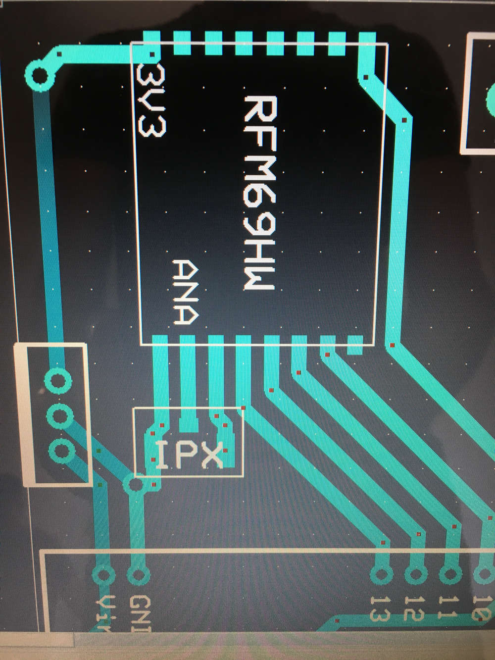
@tsunami - i dont know the range, but I have designed a PCB with SMA connector for RFM69HW. You can check out my files how I did it.
https://www.openhardware.io/view/389/EasyNewbie-PCB-RFM69-HWW-edition-for-MySensors
-
@tsunami Your range depends on a number of factors such as frequency, antenna type, power output and obstructions to the signal path.
To your questions:- Yes
- No - A bare wire quarter wave antenna is usually what is inside the rubber duck, so it is no better performing than a bare wire, it is more about appearance.
- No experience at this frequency, but it begs the question why was it selected?
Unless you field test 915MHz on a quarter-wave for the locations 200m apart you will not know if it will work with any obstructions, but I would have been testing 433MHz on a temporary lashup with different antennae to ensure it did before assembling a final install.
For the remote antenna, soldering the core and screen of a suitable (for the frequency) coax direct to the RFM antenna and ground pads is the least lossy method, terminating the other end of the coax on a chassis mounted socket for your SMA antenna. Your box should be grounded back to the devices.
Personally I would have been tempted to use the box as a reflector for a dipole or quad facing the 200m target to boost directionality and gain, but if a whip works then all good.
@zboblamont thank you for your reply
how can I use box as a reflector?
connecting GND to the box is enough?
I'm going to design PCB but I don't know how is the schematic of the antenna connection to RFM which you have said above. do you have any schematic for this?
-
@tsunami - i dont know the range, but I have designed a PCB with SMA connector for RFM69HW. You can check out my files how I did it.
https://www.openhardware.io/view/389/EasyNewbie-PCB-RFM69-HWW-edition-for-MySensors
@sundberg84 thats nice, I will look into it
-
@zboblamont thank you for your reply
how can I use box as a reflector?
connecting GND to the box is enough?
I'm going to design PCB but I don't know how is the schematic of the antenna connection to RFM which you have said above. do you have any schematic for this?
@tsunami I suggest you do a bit of background reading of how antennae work, it is relatively simple once it all clicks.
- how can I use box as a reflector?
If you have a look at the site @nagelc suggested, there is a Bi-Quad down the bottom - the reflector in this case is foil, but your box may be sufficient to provide the area required for your frequency if facing the required direction. - connecting GND to the box is enough
If you are referring to the coax, both ends of the shield should be grounded if a whip is to be used and the board grounded also. If using an external dipole or quad the coax would terminate core to one leg, shield to the other, core and shield soldered to the RFM. - I'm going to design PCB but I don't know how is the schematic of the antenna connection to RFM which you have said above. do you have any schematic for this?
The RFM comes as a complete transceiver board, you have it's layout on your design, look up the datasheet - Connection for coax core goes directly to the antenna pad ANA, GND alongside it goes to the shield.
I confess to being puzzled why you are attempting this rather than purchase a Moteino or similar which has been developed and snagged, but your choice.
I reiterate my previous comment on field testing to determine whether the frequency will work reliably for the signal path in your building, anything else is just SWAG.
- how can I use box as a reflector?
-
@zboblamont thank you very much.
I'll post my result after I done it.
what was the best antenna you used for your project?@tsunami My setup is max 50m radius and 433MHz standard power RFM69s so a small 1/4 wave whip works reliably even from a below ground pump chamber 10m away.
Your 915MHz at 200m SHOULD work on 1/4 wave if obstacle free line of sight, but you could try a 2.4GHz Wifi router at one location and use a mobile at the other to test if you can see the router. I can see at least 3 neighbouring routers identified on my mobile from over 40m away through masonry, 10 on the laptop, so it's a simple enough test.
If you can see the router on either, 915MHz should be rock solid with a simple whip and no need of directional antenna.
Hello! It looks like you're interested in this conversation, but you don't have an account yet.
Getting fed up of having to scroll through the same posts each visit? When you register for an account, you'll always come back to exactly where you were before, and choose to be notified of new replies (either via email, or push notification). You'll also be able to save bookmarks and upvote posts to show your appreciation to other community members.
With your input, this post could be even better 💗
Register Login