Pir AS 312 with 2 rechargeable AAA battery. Boost needed?
-
Hi,
according to this datasheet this PIR requires an input voltage of 2.7 - 3.3V, so if powered with 2xAAA (or AA) rechargeable NiMH batteries (2.4V) it will run out of spec.
Someone has tested it with this voltage?
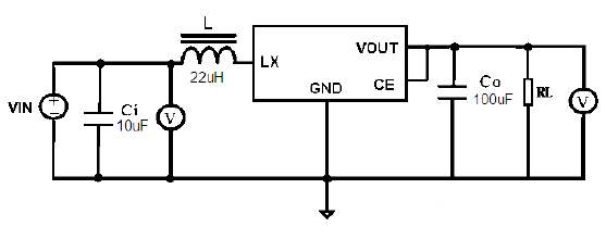
If it does not working well, I have found this ME218833C boost converter that seems adequate to the job:
-
Low quiescent current (13μA)
-
Chip Enable Pin to enable and disable the circuit on demand
-
-
Hi,
according to this datasheet this PIR requires an input voltage of 2.7 - 3.3V, so if powered with 2xAAA (or AA) rechargeable NiMH batteries (2.4V) it will run out of spec.
Someone has tested it with this voltage?
If it does not working well, I have found this ME218833C boost converter that seems adequate to the job:
-
Low quiescent current (13μA)
-
Chip Enable Pin to enable and disable the circuit on demand
@franz-unix i don't know how you will handle the pir in your software but generally the pir needs to be powered all the time so no need for shutdown mode in your boost converter. The other thing is that pir doesn't linke noisy power supply, and dc converters are rather noisy especially in low current area. I would recommend to use higher voltage and ldo voltage regulator. You can find some ldos with very low quiescent current. You can use li ion rechargable battery and 3v ldo.
-
-
Yes, the booster will be always on to power the PIR when the board is powered by rechargeable batteries (2.4V), but the idea is that if you use two disposable batteries (3.0V) or external power (micro usb port, ICSP or FTDI), the MCU reads the VCC voltage and then shuts down the booster and the PIR is powered directly.
In other words the booster will be activated by the firmware only if VCC is below 2.7V.
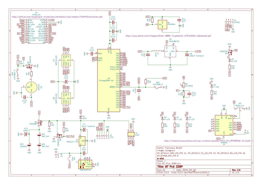
About the noise question... yes this could be a problem, but the manufacturer declare the booster as "Low ripple and Low noise", and in my schematic (see below) I have inserted a dedicated capacitor for the PIR, so I hope this is enough.
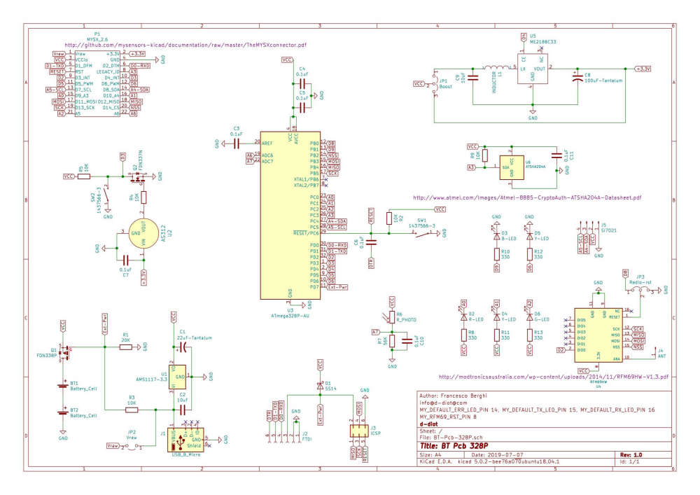
I prefer to stay with AAA batteries because I want to keep the global dimension of the node as low as possible and with this type of batteries I can power the radio module and the MCU directly from battery, saving some mA.
-
Yes, the booster will be always on to power the PIR when the board is powered by rechargeable batteries (2.4V), but the idea is that if you use two disposable batteries (3.0V) or external power (micro usb port, ICSP or FTDI), the MCU reads the VCC voltage and then shuts down the booster and the PIR is powered directly.
In other words the booster will be activated by the firmware only if VCC is below 2.7V.
About the noise question... yes this could be a problem, but the manufacturer declare the booster as "Low ripple and Low noise", and in my schematic (see below) I have inserted a dedicated capacitor for the PIR, so I hope this is enough.
I prefer to stay with AAA batteries because I want to keep the global dimension of the node as low as possible and with this type of batteries I can power the radio module and the MCU directly from battery, saving some mA.
@franz-unix if the ME2188 was really low noise and low ripple it would be good idea to use it. Unfortunetely there is nothing about it in the datasheet axcept for manufacturer declaration ... no data to support this declarations so it sounds rather not convincing. But if You have time to test it go for it :)
-
Yes, the booster will be always on to power the PIR when the board is powered by rechargeable batteries (2.4V), but the idea is that if you use two disposable batteries (3.0V) or external power (micro usb port, ICSP or FTDI), the MCU reads the VCC voltage and then shuts down the booster and the PIR is powered directly.
In other words the booster will be activated by the firmware only if VCC is below 2.7V.
About the noise question... yes this could be a problem, but the manufacturer declare the booster as "Low ripple and Low noise", and in my schematic (see below) I have inserted a dedicated capacitor for the PIR, so I hope this is enough.
I prefer to stay with AAA batteries because I want to keep the global dimension of the node as low as possible and with this type of batteries I can power the radio module and the MCU directly from battery, saving some mA.
@franz-unix said in Pir AS 312 with 2 rechargeable AAA battery. Boost needed?:
About the noise question... yes this could be a problem, but the manufacturer declare the booster as "Low ripple and Low noise", and in my schematic (see below) I have inserted a dedicated capacitor for the PIR, so I hope this is enough.
It's a PFM step up to be efficient with low loads, meaning the frequency of the noise will change a lot and it is much harder to filter. You might want to include on your PCB an option to go through a ldo (that you can of course bypass), so if the step up is too noisy you can use one with a bit higher output voltage and use the ldo to filter the output a bit more.
But I agree with @rozpruwacz a li-ion battery with a ldo like XC6206 sounds like a way more simple option and it's also easy to make it more compact than with 2 AA/AAA.
-
@rozpruwacz The ME2188 is quite inexpensive (€0.0574 ) so I will test it for sure. It is available also with different Vout voltages, so if it does its job could be an interesting option to power other type of sensors. This article is about the ME2108, which seems to be the predecessor of the ME2188 and the author says that the output voltage is clean and stable (tested with oscilloscope).
@Nca78 This XC6206 seems a good ldo vreg, thank you for the info. About the Li-ion battery, it seems to be a general agreement (see this topic for example) about the fact that the best option to power a node is with AA or AAA batteries. In fact one of the advantages is that you don't need to step up or down the voltage to power the radio and the MCU.
Yesterday I have had another idea for the circuit: the substitution of the manual jumper JP3 with 3 mosfet (Q3-Q4-Q5).
In this way you can completely exclude the booster circuit when not necessary (Vcc >= 2.7V) without manual adjustment of the jumper. Just put you batteries (disposable or rechargeable) in and... boom, the MCU will automatically do the job.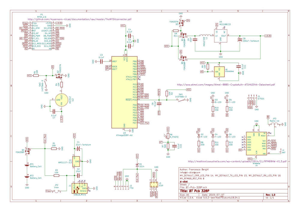
-
@rozpruwacz The ME2188 is quite inexpensive (€0.0574 ) so I will test it for sure. It is available also with different Vout voltages, so if it does its job could be an interesting option to power other type of sensors. This article is about the ME2108, which seems to be the predecessor of the ME2188 and the author says that the output voltage is clean and stable (tested with oscilloscope).
@Nca78 This XC6206 seems a good ldo vreg, thank you for the info. About the Li-ion battery, it seems to be a general agreement (see this topic for example) about the fact that the best option to power a node is with AA or AAA batteries. In fact one of the advantages is that you don't need to step up or down the voltage to power the radio and the MCU.
Yesterday I have had another idea for the circuit: the substitution of the manual jumper JP3 with 3 mosfet (Q3-Q4-Q5).
In this way you can completely exclude the booster circuit when not necessary (Vcc >= 2.7V) without manual adjustment of the jumper. Just put you batteries (disposable or rechargeable) in and... boom, the MCU will automatically do the job.@franz-unix said in Pir AS 312 with 2 rechargeable AAA battery. Boost needed?:
About the Li-ion battery, it seems to be a general agreement (see this topic for example) about the fact that the best option to power a node is with AA or AAA batteries. In fact one of the advantages is that you don't need to step up or down the voltage to power the radio and the MCU.
There is no one "best option". The power supply heavily depends on the project requirements. The PIR sensor requires noiseless voltage between 2.7 and 3.3v. This makes use of 2xAA problematic. In my opinion for such a project higher voltage supply with low quiescent current ldo is the best option. And it happens that li-ion battery with its voltage range and 3v ldo makes them perfect match. At least this is how I did it in my home and it works nice ( https://www.openhardware.io/view/610/MySXMotion). I went even further in my project and there is two ldos, one for pir and one for mcu + rf module as those two components creates large spikes in current flow as they work making supply voltage noisy.
PS. The other benefit of rechargable batteries is that they are rechargable :) so you don't need to remember to buy batteries when you go out of them.
-
If you have room for a AA, an LiFePo4 battery is right in the sweet spot.
I have seen LiFePo4 AAA batteries, but they are really hard to find.@nagelc The LiFePo4 batteries will be perfect (AA and AAA), but I arrived at your same conclusion: a little bit to exotic respect to standard alkaline or NiMH batteries.
@rozpruwacz Nice board, is similar to what I want, but unfortunately not exactly the same. I prefer to have one single board to simplify the build and external case design (3d-printable).
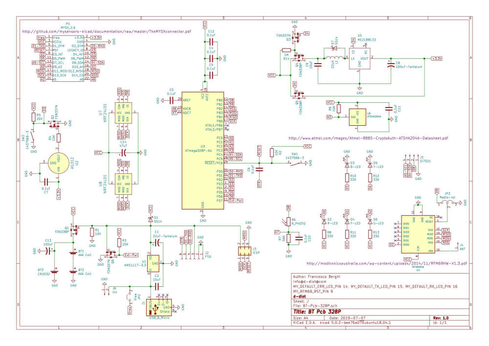
Thanks to your suggestion, I have modified a little bit the circuit:
Some consideration and board features:
-
Added footprint for CR2032 coin cell and dedicated 100 uF capacitor to prevent problem related to the low discharge rate of the battery.
-
Added a flyback diode across the inductor to discharge voltage spikes when the circuit is disconnected (mosfet Q3 - Pin D4). Not sure if it is strictly necessary... but just in case!
-
Multiple power options: 2xAAA batteries, 1xCR2032, micro USB (phone charger), J6 pin header. When powered from an external source through USB port or J6, the voltage can be between 4 and 12V. When you power the board through FTDI or ICSP make sure that the voltage is 3.3V, otherwise the radio module will be damaged!
-
Mosfet Q1 offers a reverse polarity protection to the board if the batteries are inserted in the wrong way. It cut off also the batteries compartment when an external power source is present, so you don't have to remove the batteries while powering the board via FTDI, ICSP, USB or J6
-
When VCC is below 2.7V (AAA rechargeable batteries) the boost circuit is activated by the MCU (Pin D4). When VCC is above 2.7V (disposable AAA batteries or CR2032) the circuit is disabled and the PIR is powered directly form VCC (see Q3-Q4-Q5)
-
To increase the battery life, the photoresistor is powered through PIN D5, only when the node is awake. During sleep D5 will be set to LOW, so no current waste.
-
Two momentary switch: 1 for MCU reset and 1 to force the node to wake up
-
Motion led (D3) and low battery / external powerl ed (D5) configurable in the firmware, plus radio activity LEDs
-
Header for Si7021 breakout
-
AS312 Pir with mounting holes for a standard fresnel lens like the one present in the HC-SR501
-
MYSX 2.6 connector to add other sensors.
-
ATSHA204A for security signing
-
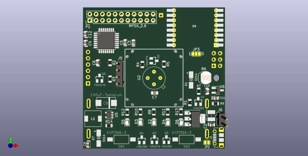
Size: 57x57 mm (not so small but also not so big)
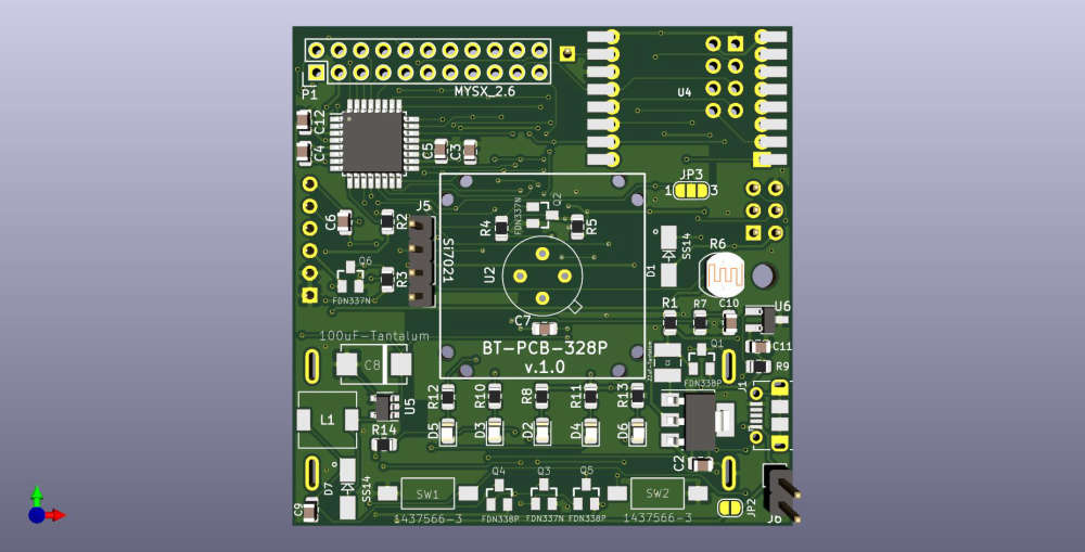
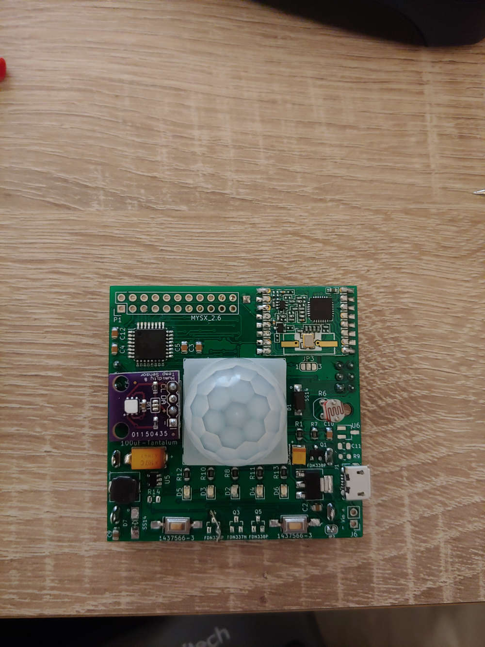
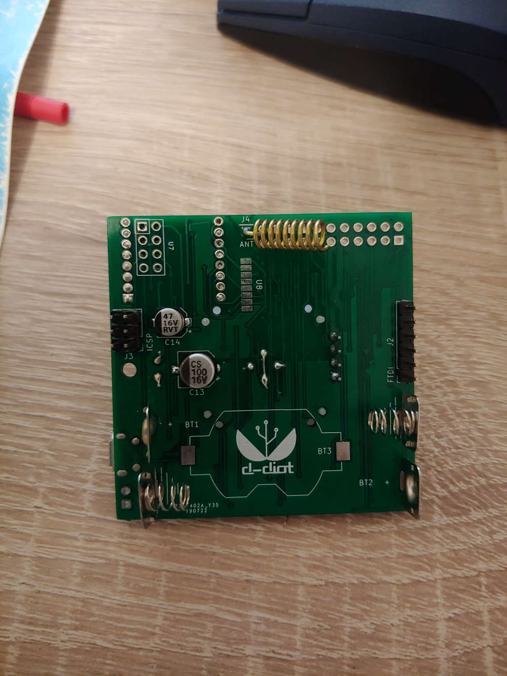
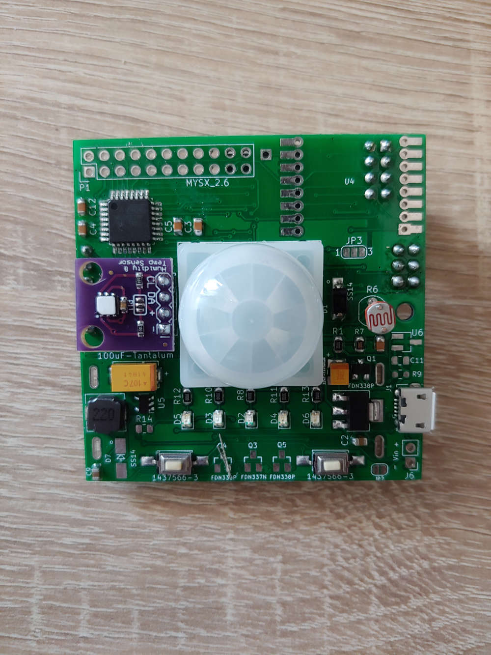
This is how the board looks like
It is still under development, but if someone is interested, the Kicad project is available on github.
... Well the next step is to test the ME2188 boost converter... I hope that it can do its job without triggering false positive on the PIR sensors!
-
-
@koresh Great! Thank you for your suggestion! :wink:
Do you have had any problem with false positive on the PIR sensors with this booster?
Another thing that I'm worried about is that the booster can introduce some sort of noise into the board and this can affect the quality of the radio signal. Do you have observed this kind of problem?
One Last (boring :joy: ) question... Have you placed a flyback diode across the inductor? I'm not sure if this component is strictly necessary.
I have made some progress with the board: added support for NRF24 radio modules (SMD and THT).
-
Update: in this days I'm testing the board and... I have a problem when the booster is activated by the MCU (VCC < 2.8V -> Pin D4 High).
In this situation the current goes very high (800 mA) and the boost coverter becomes very hot after few seconds, so it seems that somewhere a short circuit is present.
I have made this tests, but nothing has solved the issue:
-
Removed Q4 and Q5 mosfet and R14, just to simplify the circuit and connected the inductor directly to VCC with a jumper wire
-
Substituted the boost converter with a new one
-
Tried different values of R14 (1M, 300K, 10K)
-
Resoldered the inductor and the tantalum capacitor
I can not see any mistake in my schematics and to my eyes it is equivalent to the one reported in the datasheet (except for the CE pin that in my case is connected to Pin D4 of the atmega, instead of Vout), so another point of view may help.
Thanks in advance for the support
-
-
Hi guys, problem solved :wink:
The high current issue was caused by the damn flyback diode (D7).
Now the boost converter works as expected and without triggering false positive issue on the PIR (AS312).
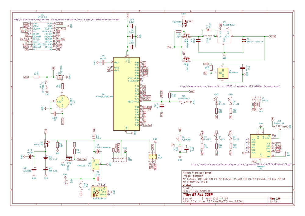
No problem also with the radio module (RFM69@868 Mhz). Not yet tested the board with a NRF24L01 radio module (THT or SMD) but I have both modules, so it is just a matter of time.After some testing I have decided to remove Q3, Q4 and Q5 because the boost converter (ME2188C33) when not enabled through the CE PIN (driven by D4 of the ATMega) act as sort of "bypass" for VCC.
With 2xAAA rechargeable batteries at 2.4V I have had some stability problem with the MCU (reset), but I have solved setting the frequency and the fuses to work at 1 Mhz (with MYSBootloader). Is it normal that an ATMega328 at 8 Mhz is unstable at 2.4V?
The last thing that I have to change is the circuit of the blu led (D3)... The typical voltage drop of this led is 3.0V, so with 2xAAA batteries and 2.4V the brightness is to low, so the idea is to power it with the 3.3V out of the boost converter, controlling the brightness through an N-Mosfet, driven by PIN D5 of the AtMega.
The firmware is under testing and is available here
Below the updated schematics.
-
Hi guys, problem solved :wink:
The high current issue was caused by the damn flyback diode (D7).
Now the boost converter works as expected and without triggering false positive issue on the PIR (AS312).
No problem also with the radio module (RFM69@868 Mhz). Not yet tested the board with a NRF24L01 radio module (THT or SMD) but I have both modules, so it is just a matter of time.After some testing I have decided to remove Q3, Q4 and Q5 because the boost converter (ME2188C33) when not enabled through the CE PIN (driven by D4 of the ATMega) act as sort of "bypass" for VCC.
With 2xAAA rechargeable batteries at 2.4V I have had some stability problem with the MCU (reset), but I have solved setting the frequency and the fuses to work at 1 Mhz (with MYSBootloader). Is it normal that an ATMega328 at 8 Mhz is unstable at 2.4V?
The last thing that I have to change is the circuit of the blu led (D3)... The typical voltage drop of this led is 3.0V, so with 2xAAA batteries and 2.4V the brightness is to low, so the idea is to power it with the 3.3V out of the boost converter, controlling the brightness through an N-Mosfet, driven by PIN D5 of the AtMega.
The firmware is under testing and is available here
Below the updated schematics.
@franz-unix said in Pir AS 312 with 2 rechargeable AAA battery. Boost needed?:
Is it normal that an ATMega328 at 8 Mhz is unstable at 2.4V?
Yes it is. Minimum voltage is 2.7V at 10MHz and 1.8V at 4MHz so at 8MHz the minimum voltage is 2.4V.
-
@franz-unix said in Pir AS 312 with 2 rechargeable AAA battery. Boost needed?:
After some testing I have decided to remove Q3, Q4 and Q5 because the boost converter (ME2188C33) when not enabled through the CE PIN (driven by D4 of the ATMega) act as sort of "bypass" for VCC.
I have the same "problem" with ME2188, although it seems to be more of an advantage for you. I have no mention of this in the datasheet I have, do you have a datasheet stating this ?
@nca78 No the datasheet that I have says nothing about what appens when CE pin is low.
I have discovered this behaviour when testing the board, but it is coherent with the diagram block of the IC reported in this datasheet.
In any case (booster on or off) the current will flow through the inductor, so it is not a real bypass, but the PIR works good in both situation and I have not observed any strange current or voltage spike.
Do you need to completly disconnect the Vout when the boost converter is disabled? Maybe you can obtain this connecting a p-mosfet and a n-mosfet (like Q3 and Q4), but on the Vout rail and drive the n-mos gate with the same pin that you use to enable the boost converter
-
@nca78 No the datasheet that I have says nothing about what appens when CE pin is low.
I have discovered this behaviour when testing the board, but it is coherent with the diagram block of the IC reported in this datasheet.
In any case (booster on or off) the current will flow through the inductor, so it is not a real bypass, but the PIR works good in both situation and I have not observed any strange current or voltage spike.
Do you need to completly disconnect the Vout when the boost converter is disabled? Maybe you can obtain this connecting a p-mosfet and a n-mosfet (like Q3 and Q4), but on the Vout rail and drive the n-mos gate with the same pin that you use to enable the boost converter
@franz-unix said in Pir AS 312 with 2 rechargeable AAA battery. Boost needed?:
I have discovered this behaviour when testing the board, but it is coherent with the diagram block of the IC reported in this datasheet.
Yes I should have a better look at those. Even the typical application circuit on first page was obvious with wiring of CE from VOUT :)
Do you need to completly disconnect the Vout when the boost converter is disabled? Maybe you can obtain this connecting a p-mosfet and a n-mosfet (like Q3 and Q4), but on the Vout rail and drive the n-mos gate with the same pin that you use to enable the boost converter
Yes I need the output to be disconnected, I use a 5V sensor from a li-ion battery and I need that sensor to be off most of the time. I decided to take the lazy solution and use a power switch, triggered with the same pin than the EN pin of ME2188.
-
@franz-unix said in Pir AS 312 with 2 rechargeable AAA battery. Boost needed?:
I have discovered this behaviour when testing the board, but it is coherent with the diagram block of the IC reported in this datasheet.
Yes I should have a better look at those. Even the typical application circuit on first page was obvious with wiring of CE from VOUT :)
Do you need to completly disconnect the Vout when the boost converter is disabled? Maybe you can obtain this connecting a p-mosfet and a n-mosfet (like Q3 and Q4), but on the Vout rail and drive the n-mos gate with the same pin that you use to enable the boost converter
Yes I need the output to be disconnected, I use a 5V sensor from a li-ion battery and I need that sensor to be off most of the time. I decided to take the lazy solution and use a power switch, triggered with the same pin than the EN pin of ME2188.
@nca78 All clear! What's your experience with this ME2188 booster? My feedback is positive: cheap, low power consumption, at least on the basis my measurement (not so accurate), and no noise that interfere with the radio module and the AS312 PIR.
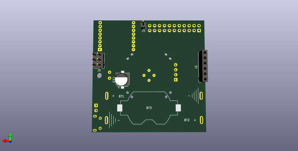
Below the board (v.1.0) with 2xAAA batteries and RFM69 radio module
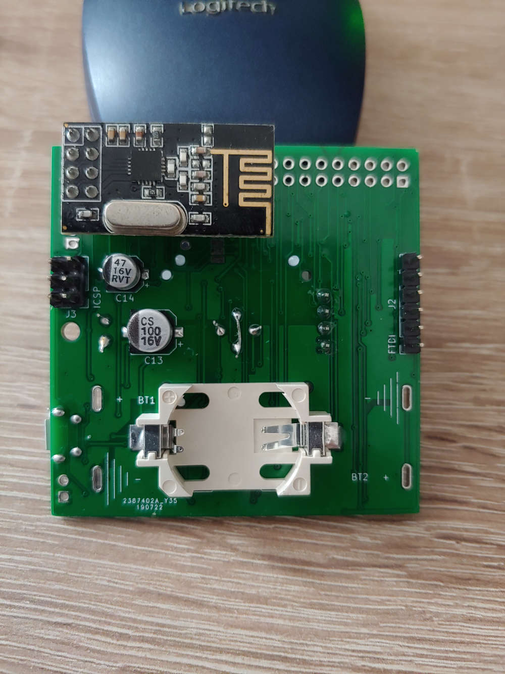
CR2032 battery and NRF24 radio module (THT)
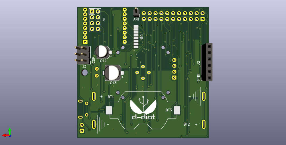
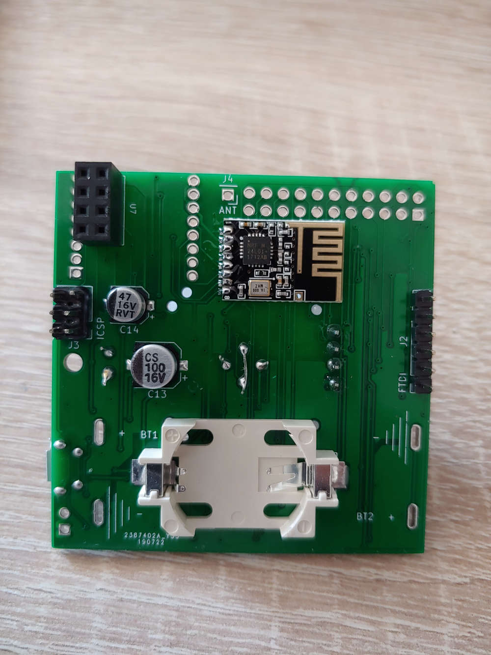
CR2032 battery and NRF24 radio module (SMD)
The board v.2.0 is coming. If someone is interested, here all the project files (Kicad)
-
@nca78 All clear! What's your experience with this ME2188 booster? My feedback is positive: cheap, low power consumption, at least on the basis my measurement (not so accurate), and no noise that interfere with the radio module and the AS312 PIR.
Below the board (v.1.0) with 2xAAA batteries and RFM69 radio module
CR2032 battery and NRF24 radio module (THT)
CR2032 battery and NRF24 radio module (SMD)
The board v.2.0 is coming. If someone is interested, here all the project files (Kicad)
@franz-unix said in Pir AS 312 with 2 rechargeable AAA battery. Boost needed?:
My feedback is positive: cheap, low power consumption, at least on the basis my measurement (not so accurate), and no noise that interfere with the radio module and the AS312 PIR.
At least no visible interference with the radio module, but you might get some.
And for RF radiation, interferences and range, no clearance/orientation of the antennas is not good too. -
@franz-unix said in Pir AS 312 with 2 rechargeable AAA battery. Boost needed?:
My feedback is positive: cheap, low power consumption, at least on the basis my measurement (not so accurate), and no noise that interfere with the radio module and the AS312 PIR.
At least no visible interference with the radio module, but you might get some.
And for RF radiation, interferences and range, no clearance/orientation of the antennas is not good too.@scalz with the RFM69 radio module (868 Mhz) I can cover the whole house (about 100 m2), with 3 walls between the gateway and the node, so, for my use case is adequate.
With the NRF24 radio module (THT version) I have the same (poor) range that I can obtain with an Arduino and the same radio module connected with jumper wires, so on the basis of my test the quality of the radio signal is not affected by the boost converter.
I have not yet deeply tested the pcb with the smd version of the NRF24 radio module.
In any case do you have any suggestion for a better orientation/clearance of the antenna? Please note that for the RFM69 radio module you can place the antenna in any direction or side of the PCB that you prefer.