Solar Energy Harvesting for wireless motes
-
OK, I think this one's the winner: https://www.openhardware.io/dl/5b8ff8a3d376570b051a91ed/design/schematic_solarLDO_v005.pdf
It uses only 4 parts and is compatible with any input voltage: https://www.openhardware.io/dl/5b8ff8a3d376570b051a91ed/design/schematic_solarLDO_v005.pdf Thus you can stack as many or as few solar cells in series as you want to, and the circuit should work the same regardless.
How it works: current from the solar cell/panel flows through the diode to charge a capacitor (either surface mounted to the PCB or attached to the PCB using the provided through-holes). When the voltage reaches 2.7v, the voltage detector goes high, burning off 50ma of current through the 56 ohm resistor until the voltage drops below its hysteresis point. As long as the solar cell/panel's current does not exceed 50ma, this design should work. If you need to handle an input current of greater than 50ma, then simply modify the circuit to instead connect the voltage detector output to an appropriately sized mosfet for that current, and then use that mosfet to dissipate the surplus current through a suitable resistor to ground.
In my case I'm be choosing a diode with a maximum of 100na reverse current leakage, but you can choose whatever diode you want to fit your particular trade-offs.
I presume that by choosing a different voltage detector you could just as easily charge a battery instead of a supercap, if that's what you wanted to do.
-
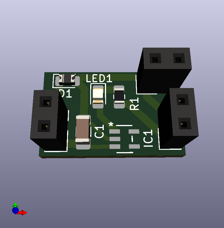
I just now sent the files to fabrication. If it tests out as expected, then I'll post the gerber files.
-
Just for fun I added an LED that will flash each time the capacitor discharges a little to stay within its maximum 2.7v. Although brief, it indicates that solar harvesting is working and that the capacitor is fully charged.
-
Just for fun I added an LED that will flash each time the capacitor discharges a little to stay within its maximum 2.7v. Although brief, it indicates that solar harvesting is working and that the capacitor is fully charged.
BTW, I found a voltage detector that consumes just 150na, so I'll probably switch to using that because it will be important for the nextgen version which prioritizes the charging of a bootstrap cap before dumping solar charge into a much larger supercap.
-
It finally dawned on me that a very solid minimalist circuit can be accomplished using just two diodes: https://www.openhardware.io/dl/5b8ff8a3d376570b051a91ed/design/schematic_solarLDO_v008.pdf
The trick to making it work is selecting a diode D2 that has a forward voltage drop of 2.7v. For instance, CMF05(TE12L,Q,M) is such a diode, and on Digikey it costs a mere 40 cents: https://www.digikey.com/product-detail/en/CMF05(TE12L%2CQ%2CM)/CMF05(TE12LQM)CT-ND/2310627
The result is a circuit that's not only inexpensive but can withstand any voltage that might be applied to it and, in realistic terms, any charge current that it's likely to encounter as well. And by picking diode D1 to have a low forward current (and for that, any common diode will do), it will charge quickly as well. So, better, faster, cheaper. Usually you only get to pick two of those. :-)
-
@neverdie what will prevent your supercap from discharging through D2 ?
When current flowing through the diode gets low, the forward voltage gets lower too so your supercap will be drained.@nca78 Thanks for pointing that out. I don't have in my possession the diode with the 2.7v forward voltage drop, so I ran some tests on a red LED insteaad. According to my multimeter, the red LED has a forward voltage drop of 1.8v. I hooked it into a uCurrent Gold to measure current and then decreased the voltage below 1.8v to see how the LED current reacted. You are right. Voltage had dropped all the way to 1.4v before I could no longer see any detectable current on the micro amp scale. Then, switching to the nano-amp scale, it wasn't until I had reduced the voltage to one volt that I could no longer discern any current on the nano amp scale. I had thought the current would cut-off much sooner than that, but I was wrong. Thank you once again.
Back to the drawing board!
-
@neverdie what will prevent your supercap from discharging through D2 ?
When current flowing through the diode gets low, the forward voltage gets lower too so your supercap will be drained. -
@nca78
What if a 2.7v zener diode, reverse biased, were used instead? Would it have essentially the same problem?Scratch that. Probably not, except in limited cases, and even those might require hand selected zeners.OK, for an extra 40 cents, this new circuit should work perfectly without more than 150na of current drain: https://www.openhardware.io/dl/5b8ff8a3d376570b051a91ed/design/schematic_solarLDO_v011.pdf
I suspect 150na is less than the self discharge rate for any supercap.
For larger solar panels, expunging surplus capacitor charge through an nfet would be the prudent way to go, but this circuit should work for the tiny solar panels that I'm currently focused on, which for sure are producing less than a milliamp of current. The circuit retains the ability to withstand any input voltage, provided that the input current is guaranteed to be less than 10ma, which is the absolute maximum provided by the datasheet.
It's a good time to be alive. Not long ago these ultra low current drain parts didn't even exist--at least not at $0.82 for single unit quantities. :)
That said, there are a number of different ways to attack this problem. Maybe an even cheaper way exists that can withstand any input voltage (say, up to 50 or 60v DC worst case)? That's really the only complicating factor. If one assumes less than 12v input voltage, or even less than 20v input voltage, then I can see at least some other possibilities that would work just as well, if not better.
-
I forgot to mention: another advantage is that it can start charging the capacitor at lower solar voltages than what a pre-made LDO (at least the ones that can withstand 40v) can. AFAIK, the pre-made 40v LDO's don't pass current until the voltages are 2v+, or thereabouts. In theory, this one could start charging at around 0.4v to 0.8v (depending on how many diodes I end up needing to guarantee a full-shutoff at the PMOS).
-
Looks interesting. How effective are these devices? What type of solar panel is compatible with this device?
@marcosbe We're using solar cells scavenged from solar keychains. They put out less than 10ua in current under indoor lighting conditions.
I tested the version 11 circuit (above), and it works. I subsequently added an LED to the discharge path so that it blinks during the discharge. This way you can confirm visually when the cap is charged. With just a 100uF cap instead of a supercap, it blinks fairly often even with just relatively weak indoor lighting.
-
@marcosbe We're using solar cells scavenged from solar keychains. They put out less than 10ua in current under indoor lighting conditions.
I tested the version 11 circuit (above), and it works. I subsequently added an LED to the discharge path so that it blinks during the discharge. This way you can confirm visually when the cap is charged. With just a 100uF cap instead of a supercap, it blinks fairly often even with just relatively weak indoor lighting.
@neverdie An interesting experiment, but can you clarify that by indoor lighting conditions you mean that harvesting is active only when lights are on, or does daylight continue to produce at say a lower rate?
-
@neverdie An interesting experiment, but can you clarify that by indoor lighting conditions you mean that harvesting is active only when lights are on, or does daylight continue to produce at say a lower rate?
@zboblamont These particular solar cells seem to perform about the same regardless of whether the weak indoor light is sourced from indoor LED lights or from outdoor light that has leaked into the room from behind closed shades.
That's a lot different than most solar cells, which may output no current at all from even bright indoor LED lighting but which will outperform these cells from sunlight that has leaked into the room from behind closed curtains. That's one of the two things that makes these scavanged cells interesting. The other thing is that they have a much higher voltage, even under weak lighting. Go figure. I don't know why they are that way, so I just accept it as empirical fact.
FWIW, for testing purposes, the solar cell industry has arbitrarily defined weak indoor lighting as 200 lux, which in my book is actually fairly bright. I would estimate that these cells still perform at below 200 lux. For instance, I can get LED blinks off my charge circuit just from pointing the cell at my TV from across the room in an otherwise completely dark house late at night. Maybe later I'll dig out my lux meter and take some measurements.
-
@zboblamont These particular solar cells seem to perform about the same regardless of whether the weak indoor light is sourced from indoor LED lights or from outdoor light that has leaked into the room from behind closed shades.
That's a lot different than most solar cells, which may output no current at all from even bright indoor LED lighting but which will outperform these cells from sunlight that has leaked into the room from behind closed curtains. That's one of the two things that makes these scavanged cells interesting. The other thing is that they have a much higher voltage, even under weak lighting. Go figure. I don't know why they are that way, so I just accept it as empirical fact.
FWIW, for testing purposes, the solar cell industry has arbitrarily defined weak indoor lighting as 200 lux, which in my book is actually fairly bright. I would estimate that these cells still perform at below 200 lux. For instance, I can get LED blinks off my charge circuit just from pointing the cell at my TV from across the room in an otherwise completely dark house late at night. Maybe later I'll dig out my lux meter and take some measurements.
@neverdie Thanks for that clarification, intriguing possibilities indeed, who'd have thunk...
Not concerned over what what light levels generate which level of power rather than the principle of continuity, i.e. day/artificial light agnostic.
It would indeed be ironic in the leap from tungsten to LED for illumination, that alongside lower energy consumption, the possibility of recycling part of that reduced energy coincides.
Bravo.. -
@neverdie Thanks for that clarification, intriguing possibilities indeed, who'd have thunk...
Not concerned over what what light levels generate which level of power rather than the principle of continuity, i.e. day/artificial light agnostic.
It would indeed be ironic in the leap from tungsten to LED for illumination, that alongside lower energy consumption, the possibility of recycling part of that reduced energy coincides.
Bravo..@zboblamont I made the circuit able to withstand any input voltage because I wanted to stack of bunch of solar cells in series and thereby, if possible, manage to charge even using just moonlight. Well, after experimenting with that concept last night, it looks as though solar cells just aren't additive in that way, at least not under ultra low lighting conditions like moonlight-only.
-
@zboblamont I made the circuit able to withstand any input voltage because I wanted to stack of bunch of solar cells in series and thereby, if possible, manage to charge even using just moonlight. Well, after experimenting with that concept last night, it looks as though solar cells just aren't additive in that way, at least not under ultra low lighting conditions like moonlight-only.
@neverdie Ah, Texans - "don't the stars look purty t'night?".... "Yeah, but the moon is only producin' 2mV honey..." Romance is not dead but buried...:sweat_smile:
Just kidding, brilliant stuff... ;) -
@neverdie Ah, Texans - "don't the stars look purty t'night?".... "Yeah, but the moon is only producin' 2mV honey..." Romance is not dead but buried...:sweat_smile:
Just kidding, brilliant stuff... ;)@zboblamont I still have hopes if that if I can just get even 1ua from moonlight, even at a mere 20mv, that I'll be able to collect it and eventually harvest it using: https://www.openhardware.io/view/732/Extreme-Energy-Harvester
That may yet still work.... I think maybe the reason why stringing a bunch of cells in series doesn't work is that at very low light levels, the leakage currents become dominant. Except, if that's so, why does it still show a high voltage?
Fortunately, I don't have an actual need to harvest only moonlight. It's just that if I could, then my gear would be good enough to run pretty much anywhere, other than in complete blackness.
Of course, if anyone has ideas on how to harvest moonlight, then please do post.
-
@zboblamont I still have hopes if that if I can just get even 1ua from moonlight, even at a mere 20mv, that I'll be able to collect it and eventually harvest it using: https://www.openhardware.io/view/732/Extreme-Energy-Harvester
That may yet still work.... I think maybe the reason why stringing a bunch of cells in series doesn't work is that at very low light levels, the leakage currents become dominant. Except, if that's so, why does it still show a high voltage?
Fortunately, I don't have an actual need to harvest only moonlight. It's just that if I could, then my gear would be good enough to run pretty much anywhere, other than in complete blackness.
Of course, if anyone has ideas on how to harvest moonlight, then please do post.
@neverdie "I still have hopes if that if I can just get even 1ua from moonlight..."
Sounds like a job for a parabolic concentator increasing luminance on the panel, albeit at the risk of frying at the merest hint of sunlight.. -
@neverdie "I still have hopes if that if I can just get even 1ua from moonlight..."
Sounds like a job for a parabolic concentator increasing luminance on the panel, albeit at the risk of frying at the merest hint of sunlight..@zboblamont said in Solar Energy Harvesting for wireless motes:
@neverdie "I still have hopes if that if I can just get even 1ua from moonlight..."
Sounds like a job for a parabolic concentator increasing luminance on the panel, albeit at the risk of frying at the merest hint of sunlight..It would be ungainly, but that could work. For instance, ultra-low-lux security cameras have a little flag that rapidly pops up (faster than you can blink) to cover an imager and protect it against overexposure in those kinds of scenarios.
Hello! It looks like you're interested in this conversation, but you don't have an account yet.
Getting fed up of having to scroll through the same posts each visit? When you register for an account, you'll always come back to exactly where you were before, and choose to be notified of new replies (either via email, or push notification). You'll also be able to save bookmarks and upvote posts to show your appreciation to other community members.
With your input, this post could be even better 💗
Register Login