Solar Energy Harvesting for wireless motes
-
@nca78
What if a 2.7v zener diode, reverse biased, were used instead? Would it have essentially the same problem?Scratch that. Probably not, except in limited cases, and even those might require hand selected zeners.OK, for an extra 40 cents, this new circuit should work perfectly without more than 150na of current drain: https://www.openhardware.io/dl/5b8ff8a3d376570b051a91ed/design/schematic_solarLDO_v011.pdf
I suspect 150na is less than the self discharge rate for any supercap.
For larger solar panels, expunging surplus capacitor charge through an nfet would be the prudent way to go, but this circuit should work for the tiny solar panels that I'm currently focused on, which for sure are producing less than a milliamp of current. The circuit retains the ability to withstand any input voltage, provided that the input current is guaranteed to be less than 10ma, which is the absolute maximum provided by the datasheet.
It's a good time to be alive. Not long ago these ultra low current drain parts didn't even exist--at least not at $0.82 for single unit quantities. :)
That said, there are a number of different ways to attack this problem. Maybe an even cheaper way exists that can withstand any input voltage (say, up to 50 or 60v DC worst case)? That's really the only complicating factor. If one assumes less than 12v input voltage, or even less than 20v input voltage, then I can see at least some other possibilities that would work just as well, if not better.
-
I forgot to mention: another advantage is that it can start charging the capacitor at lower solar voltages than what a pre-made LDO (at least the ones that can withstand 40v) can. AFAIK, the pre-made 40v LDO's don't pass current until the voltages are 2v+, or thereabouts. In theory, this one could start charging at around 0.4v to 0.8v (depending on how many diodes I end up needing to guarantee a full-shutoff at the PMOS).
-
Looks interesting. How effective are these devices? What type of solar panel is compatible with this device?
@marcosbe We're using solar cells scavenged from solar keychains. They put out less than 10ua in current under indoor lighting conditions.
I tested the version 11 circuit (above), and it works. I subsequently added an LED to the discharge path so that it blinks during the discharge. This way you can confirm visually when the cap is charged. With just a 100uF cap instead of a supercap, it blinks fairly often even with just relatively weak indoor lighting.
-
@marcosbe We're using solar cells scavenged from solar keychains. They put out less than 10ua in current under indoor lighting conditions.
I tested the version 11 circuit (above), and it works. I subsequently added an LED to the discharge path so that it blinks during the discharge. This way you can confirm visually when the cap is charged. With just a 100uF cap instead of a supercap, it blinks fairly often even with just relatively weak indoor lighting.
@neverdie An interesting experiment, but can you clarify that by indoor lighting conditions you mean that harvesting is active only when lights are on, or does daylight continue to produce at say a lower rate?
-
@neverdie An interesting experiment, but can you clarify that by indoor lighting conditions you mean that harvesting is active only when lights are on, or does daylight continue to produce at say a lower rate?
@zboblamont These particular solar cells seem to perform about the same regardless of whether the weak indoor light is sourced from indoor LED lights or from outdoor light that has leaked into the room from behind closed shades.
That's a lot different than most solar cells, which may output no current at all from even bright indoor LED lighting but which will outperform these cells from sunlight that has leaked into the room from behind closed curtains. That's one of the two things that makes these scavanged cells interesting. The other thing is that they have a much higher voltage, even under weak lighting. Go figure. I don't know why they are that way, so I just accept it as empirical fact.
FWIW, for testing purposes, the solar cell industry has arbitrarily defined weak indoor lighting as 200 lux, which in my book is actually fairly bright. I would estimate that these cells still perform at below 200 lux. For instance, I can get LED blinks off my charge circuit just from pointing the cell at my TV from across the room in an otherwise completely dark house late at night. Maybe later I'll dig out my lux meter and take some measurements.
-
@zboblamont These particular solar cells seem to perform about the same regardless of whether the weak indoor light is sourced from indoor LED lights or from outdoor light that has leaked into the room from behind closed shades.
That's a lot different than most solar cells, which may output no current at all from even bright indoor LED lighting but which will outperform these cells from sunlight that has leaked into the room from behind closed curtains. That's one of the two things that makes these scavanged cells interesting. The other thing is that they have a much higher voltage, even under weak lighting. Go figure. I don't know why they are that way, so I just accept it as empirical fact.
FWIW, for testing purposes, the solar cell industry has arbitrarily defined weak indoor lighting as 200 lux, which in my book is actually fairly bright. I would estimate that these cells still perform at below 200 lux. For instance, I can get LED blinks off my charge circuit just from pointing the cell at my TV from across the room in an otherwise completely dark house late at night. Maybe later I'll dig out my lux meter and take some measurements.
@neverdie Thanks for that clarification, intriguing possibilities indeed, who'd have thunk...
Not concerned over what what light levels generate which level of power rather than the principle of continuity, i.e. day/artificial light agnostic.
It would indeed be ironic in the leap from tungsten to LED for illumination, that alongside lower energy consumption, the possibility of recycling part of that reduced energy coincides.
Bravo.. -
@neverdie Thanks for that clarification, intriguing possibilities indeed, who'd have thunk...
Not concerned over what what light levels generate which level of power rather than the principle of continuity, i.e. day/artificial light agnostic.
It would indeed be ironic in the leap from tungsten to LED for illumination, that alongside lower energy consumption, the possibility of recycling part of that reduced energy coincides.
Bravo..@zboblamont I made the circuit able to withstand any input voltage because I wanted to stack of bunch of solar cells in series and thereby, if possible, manage to charge even using just moonlight. Well, after experimenting with that concept last night, it looks as though solar cells just aren't additive in that way, at least not under ultra low lighting conditions like moonlight-only.
-
@zboblamont I made the circuit able to withstand any input voltage because I wanted to stack of bunch of solar cells in series and thereby, if possible, manage to charge even using just moonlight. Well, after experimenting with that concept last night, it looks as though solar cells just aren't additive in that way, at least not under ultra low lighting conditions like moonlight-only.
@neverdie Ah, Texans - "don't the stars look purty t'night?".... "Yeah, but the moon is only producin' 2mV honey..." Romance is not dead but buried...:sweat_smile:
Just kidding, brilliant stuff... ;) -
@neverdie Ah, Texans - "don't the stars look purty t'night?".... "Yeah, but the moon is only producin' 2mV honey..." Romance is not dead but buried...:sweat_smile:
Just kidding, brilliant stuff... ;)@zboblamont I still have hopes if that if I can just get even 1ua from moonlight, even at a mere 20mv, that I'll be able to collect it and eventually harvest it using: https://www.openhardware.io/view/732/Extreme-Energy-Harvester
That may yet still work.... I think maybe the reason why stringing a bunch of cells in series doesn't work is that at very low light levels, the leakage currents become dominant. Except, if that's so, why does it still show a high voltage?
Fortunately, I don't have an actual need to harvest only moonlight. It's just that if I could, then my gear would be good enough to run pretty much anywhere, other than in complete blackness.
Of course, if anyone has ideas on how to harvest moonlight, then please do post.
-
@zboblamont I still have hopes if that if I can just get even 1ua from moonlight, even at a mere 20mv, that I'll be able to collect it and eventually harvest it using: https://www.openhardware.io/view/732/Extreme-Energy-Harvester
That may yet still work.... I think maybe the reason why stringing a bunch of cells in series doesn't work is that at very low light levels, the leakage currents become dominant. Except, if that's so, why does it still show a high voltage?
Fortunately, I don't have an actual need to harvest only moonlight. It's just that if I could, then my gear would be good enough to run pretty much anywhere, other than in complete blackness.
Of course, if anyone has ideas on how to harvest moonlight, then please do post.
@neverdie "I still have hopes if that if I can just get even 1ua from moonlight..."
Sounds like a job for a parabolic concentator increasing luminance on the panel, albeit at the risk of frying at the merest hint of sunlight.. -
@neverdie "I still have hopes if that if I can just get even 1ua from moonlight..."
Sounds like a job for a parabolic concentator increasing luminance on the panel, albeit at the risk of frying at the merest hint of sunlight..@zboblamont said in Solar Energy Harvesting for wireless motes:
@neverdie "I still have hopes if that if I can just get even 1ua from moonlight..."
Sounds like a job for a parabolic concentator increasing luminance on the panel, albeit at the risk of frying at the merest hint of sunlight..It would be ungainly, but that could work. For instance, ultra-low-lux security cameras have a little flag that rapidly pops up (faster than you can blink) to cover an imager and protect it against overexposure in those kinds of scenarios.
-
@neverdie "I still have hopes if that if I can just get even 1ua from moonlight..."
Sounds like a job for a parabolic concentator increasing luminance on the panel, albeit at the risk of frying at the merest hint of sunlight..@zboblamont I have the Buck Energy Harvester working now: https://www.openhardware.io/view/733/Buck-Energy-Harvester#tabs-design
However, fresh out of the box it turns out not to be compatible with the keychain fob solar cells. Why? What's not even mentioned In the LTC3388 datasheet'S executive summary introduction page is that the active quiescent current is 150-250ua, which is enough to completely overwhelm the keychain fob solar cell output of around 10ua. I thought perhaps it would instead accumulate a charge and later do a forced conversion in a burst mode, but it doesn't appear to work that way. Such a mode could probably be configured, but I don't see anything like it discussed in the datasheet, so it would require some design and prototyping. More to the point, though, is that in such a scenario, I no longer see that there's anything special about the LTC3388 versus any other buck converter. i.e. I might as well dump the LTC3388, which is fairly expensive, and replace it with a much less expensive, highly efficient buck converter that's also highly efficient running in a burst mode.
-
I notice that TI has a relatively new buck converter chip, the LM5164. In comparing it to other buck converters, what stands out about it is that it has high efficiency, even at a load current of just a milliamp:
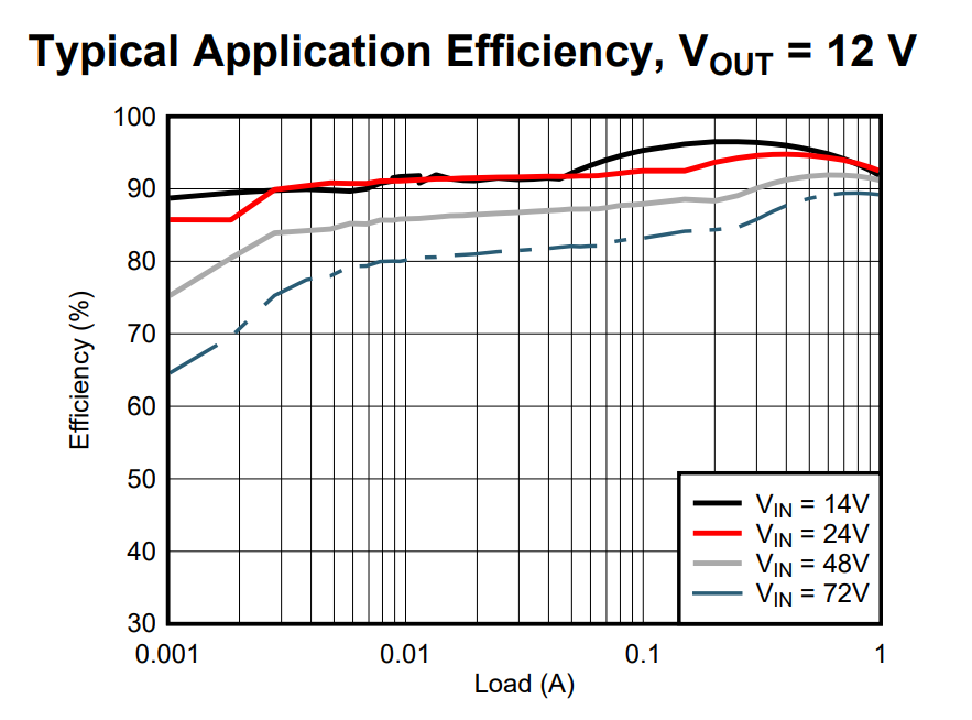
So, at least that much is impressive. However, its active current is 600-880ua, which is through the roof compared to the LTC3388, which is what led me to search for an alternative buck converter in the first place. The only way I can see to make use of it would be in very short bursts, which it fortunately seems designed to manage.
So, for that reason, for now I'll stick with the LTC3388 and leave the perfecting of the buck converter as a future optimization...
-
So, this smoking gun more or less settles it the matter regarding the LTC3388:
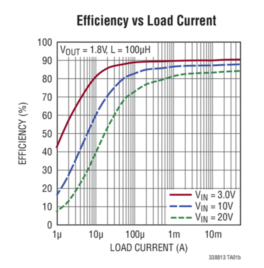
Because of low efficiency at the microamp range, neither would appear to be a good match for solar cells extracted from the key fobs. Nonetheless, it would be a good match for higher current solar cells.
-
I hadn't been aware of it until now, but apparently there do exist batteries with a very low 0.7% annual self-discharge rate, which translates into still having 70% of their original capacity a full 40 years later! http://www.tadiranbat.com/assets/white-paper-for-sensors-online-revised.pdf They're fairly pricey, but do they seem like a much simpler method for getting past the cold-start problem on most energy harvesters. Presumably nearly all motes would be obsolete after 40 years anyway, and probably even long before that.
-
Looks as though the EM8500 solar energy harvester can still function even if fed a current of just 1ua, for a total of 1uw power, and perhaps even less: https://www.emmicroelectronic.com/sites/default/files/products/datasheets/8500-ds.pdf
If I'm not mistaken, that's lower power than any other chip! And if it's price really is $2.30 for quantity 1, then that would make it one of the least expensive energy harvester chips as well.
Unfortunately, neither digikey nor mouser carry it.
-
Intended for TEGs instead of photovoltaic, the EM8900 is nonetheless impressive. According to its datasheet, it can both cold start and operate with an input voltage as low as 5mv. That's far and away better than the LTC3108, which before now I had thought was the world leader with its 20mv minimum operating voltage. https://www.emmicroelectronic.com/sites/default/files/products/datasheets/8900-ds.pdf
-
@NeverDie can't you order from https://www.cdiweb.com/products/detail/em8500a001lf24b-em-microelectronic/594464/ ?
@mfalkvidd Yup. It was when looking there for the EM-8500 that I first noticed the EM-8900 (just 79 cents, quantity one!).
Hello! It looks like you're interested in this conversation, but you don't have an account yet.
Getting fed up of having to scroll through the same posts each visit? When you register for an account, you'll always come back to exactly where you were before, and choose to be notified of new replies (either via email, or push notification). You'll also be able to save bookmarks and upvote posts to show your appreciation to other community members.
With your input, this post could be even better 💗
Register Login