💬 The Harvester: ultimate power supply for the Raybeacon DK
-
@Mishka said in 💬 The Harvester: ultimate power supply for the Raybeacon DK:
I'm going to order some Amorton panels of suitable size (less than 25x25), it will be interesting to compare them with my other amorphous cell.
I'm thinking of ordering the AM-1816CA, which AFAIK is the largest one rated for indoor and low lux. https://www.mouser.com/datasheet/2/315/panasonic_AM-1816CA-1196985.pdf
My only reason for ordering the largest would be to see what the limit is on how dim things can get in that series and still have something that can function. Maybe ordering smaller panels would make more sense, though, as they could always be added together in parallel or series. Yeah, that would make more sense I think.In addition, if you let me know what models you order, I may order one of the same too just so we can have something in common to compare results.
At very dim levels I notice that my Fluke 87v multimeter actually draws too much current off the solar cell to get an accurate open circuit voltage measurement. So, I'll have to rig up some kind of voltage following op amp buffer as an aid to doing these measurements.
@NeverDie said in 💬 The Harvester: ultimate power supply for the Raybeacon DK:
At very dim levels I notice that my Fluke 87v multimeter actually draws too much current off the solar cell to get an accurate open circuit voltage measurement. So, I'll have to rig up some kind of voltage following op amp buffer as an aid to doing these measurements.
Heh, we seem dived below 1 µA / µW level here :fish: :-)
-
@NeverDie said in 💬 The Harvester: ultimate power supply for the Raybeacon DK:
At very dim levels I notice that my Fluke 87v multimeter actually draws too much current off the solar cell to get an accurate open circuit voltage measurement. So, I'll have to rig up some kind of voltage following op amp buffer as an aid to doing these measurements.
Heh, we seem dived below 1 µA / µW level here :fish: :-)
@Mishka said in 💬 The Harvester: ultimate power supply for the Raybeacon DK:
Heh, we seem dived below 1 µA / µW level here
Looking at the datasheets for the op amps I have on hand, I'm guessing that the LTC2063 will allow an accurate measurement: https://www.analog.com/media/en/technical-documentation/data-sheets/LTC2063-2064.pdf I'll try it after my uv glue arrives.
-
@NeverDie said in 💬 The Harvester: ultimate power supply for the Raybeacon DK:
Only one way to know for sure, but I would guess that the crystalline one would drain off the current produced by the amorphous one (based partly on your theory as to why amorphous is better in low light). Worth a shot though: maybe as a compromise solution you can have the best of both worlds.
I mean connect them in series with bypass diodes so the amorphous cell can be used to bootstrap the harvester, and then crystalline cell will be workhorse during the day. Unfortunately, can't check it right now - left all my cells in the office.
Thinking out loud here, I have read about some research solar harvesters where they use a separate "pilot" solar cell to power the control electronics past the cold boot threshold.
That's a smart idea. Perhaps connect a dedicated tiny charge pump and an amorphous panel parallel to the buck-boost harvester storage capacitors?
The ideal solution would be if there were some way to re-configure multiple cells in series or parallel depending on the lighting conditions. It could default to series to push past the cold start and then switch to parallel.
A mechanical device? :-)
@Mishka said in 💬 The Harvester: ultimate power supply for the Raybeacon DK:
Perhaps connect a dedicated tiny charge pump and an amorphous panel parallel to the buck-boost harvester storage capacitors?
Maybe, but which one? I would have suggested this one, but it's no longer available: https://media.digikey.com/pdf/Data Sheets/Seiko Instruments PDFs/S-882Z.pdf
-
@NeverDie said in 💬 The Harvester: ultimate power supply for the Raybeacon DK:
I'm not at all sure that it's accurate, but that's what the lux meter said.
Wow, relatively to my built into the smartphone Sensortek STK3x1x ambient light sensor this one looks very serious.
The cell has surprisingly high voltage (2.7V) at so low light. My amorphous cell has Voc = 1.8V at 50 lux (2 m from a fluorescent lamp). Maybe yours has many more cells in series. I'm going to order some Amorton panels of suitable size (less than 25x25), it will be interesting to compare them with my other amorphous cell.
I'm also wondering would it be good o bad to connect two cells of different types - one amorphous and one crystalline.
@Mishka said in 💬 The Harvester: ultimate power supply for the Raybeacon DK:
Wow, relatively to my built into the smartphone Sensortek STK3x1x ambient light sensor this one looks very serious.
Looks as though you can get a fairly inexpensive digital light sensor from adafruit that will tell you the lux level: https://www.adafruit.com/product/4162
https://www.amazon.com/Adafruit-4162-VEML7700-Lux-Sensor/dp/B07S9TD2W1/ref=sr_1_1?keywords=Adafruit+VEML7700&qid=1583129068&sr=8-1It doesn't have the little translucent plastic dome on it though that one typically finds on lux meters. Not sure how important that is or isn't. Seems like such domes would shade the light and skew low light level readings, so maybe you'd be better off without it.
I may get one myself as a check on my lux meter.
There's also this one, a little cheaper: https://www.amazon.com/Adafruit-TSL2591-Dynamic-Digital-ADA1980/dp/B00XW2OFWW/ref=sr_1_1?keywords=Adafruit+lux+sensor&qid=1583129190&sr=8-1
I checked the adafruit library, and it prints sensor readings in lux.Not sure which one is more accurate.
-
I built the op-amp circuit, and now the open circuit readings on a solar cell are much higher than when I was taking the readings with a regular multimeter. As long as I can keep the control logic current at just a couple hundred nanoamps or so, I think I'll probably have enough voltage under even very dim lighting that I doubt cold start will be an issue.
-
@NeverDie Wow! Are you sure the lux meter is working properly? 15 lux is about as low as 25 cm from a candle fire which is awfully low.
So, since the ADP5091 is also on the list now, I think it becomes necessary to put all the mentioned power harvesters side by side so we can compare at least basic parameters. Please take a look to the Google Spreadsheet listing some of the tiny harvesters. Please note, The Analog Devices has about ten harvesters which may be described as "tiny", but so far the sheet is covering only ADP509x series. I'm going to add the LTC series later.
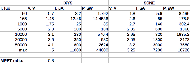
From brief analysis, it looks like the Startup Input Voltage and the Startup Input Power are placing the major constraint on PV panel. Of course, the panel should be also able to supply voltage required to cold-boot the harvester. Such, under the low-light conditions (50 lx to 100 lx in a dim room) power capabilities of both of my panels are simply not sufficient to bootstrap the SPV1050: the IXYS is too weak and works starting from 150 lx, and the SCNE is good for boost, but still require 150 lx to reach 2.6V at STORE (the data is for the charts I've posted earlier):
Therefore any panel which can reach required voltage and provide enough power should make the harvesting IC work. Please also note, that after cold-boot almost any harvester can work on a lower power (usually 1.5 - 3 times lower than it was required to start).
Also, in the table there is a class of super-tiny harvesters, namely the Cypress S6AE102(3)A and Ricoh R1800K. They can charge a store by harvesting source with less than 1µW capability. At the same time, the EM8500 looks like the most sophisticated embedded solution with lots of features. The rest of harvesters are quite nice ICs for a modular system.
@Mishka said in 💬 The Harvester: ultimate power supply for the Raybeacon DK:
What method or methods are you using to characterize your solar cells? I'm guessing in this instance that for the different illumination levels you are recording the open circuit voltage and the short circuit voltage? So as to at least try to compare apples to apples, I want to collect data on my cells in the same way that you are.
Another, complementary approach is described here: "The key characteristic of a solar cell is its ability to convert light into electricity. This is known as the power conversion efficiency (PCE) and is the ratio of incident light power to output electrical power. To determine the PCE, and other useful metrics, current-voltage (IV) measurements are performed. A series of voltages are applied to the solar cell while it is under illumination. The output current is measured at each voltage step, resulting in the characteristic 'IV curve' seen in many research papers. " https://www.ossila.com/pages/solar-cells-theory I suppose with this approach a series of curves could be produced, each for a different illumination level. Since doing that would be a lot of work, I'd like to somehow automate the testing process, but first I need to either know or decide what the process is that I want to automate.
-
@Mishka said in 💬 The Harvester: ultimate power supply for the Raybeacon DK:
What method or methods are you using to characterize your solar cells? I'm guessing in this instance that for the different illumination levels you are recording the open circuit voltage and the short circuit voltage? So as to at least try to compare apples to apples, I want to collect data on my cells in the same way that you are.
Another, complementary approach is described here: "The key characteristic of a solar cell is its ability to convert light into electricity. This is known as the power conversion efficiency (PCE) and is the ratio of incident light power to output electrical power. To determine the PCE, and other useful metrics, current-voltage (IV) measurements are performed. A series of voltages are applied to the solar cell while it is under illumination. The output current is measured at each voltage step, resulting in the characteristic 'IV curve' seen in many research papers. " https://www.ossila.com/pages/solar-cells-theory I suppose with this approach a series of curves could be produced, each for a different illumination level. Since doing that would be a lot of work, I'd like to somehow automate the testing process, but first I need to either know or decide what the process is that I want to automate.
What method or methods are you using to characterize your solar cells? I'm guessing in this instance that for the different illumination levels you are recording the open circuit voltage and the short circuit voltage?
@NeverDie exactly. That was a quick and dirty measurement using a multimeter. The P (µW) value was calculated as V * I * 0.8 (MPP assumed 80%, I must multiply to 0.8^2 instead). My intent was to describe the panels in dependency of different illuminance (which must be also denoted by E instead).
Finding MPP on IV curve is the right method to characterize a cell. But that would require fixing illuminance at some point (and is more complicated), when I was more interested in different light conditions. Most cells are rated at 200 lux indoors, and one sun (more than 100k lux) outdoors. Perhaps 50 lux indoors (a typical light at home) and 1000 lux (cloudy day) is more practical for low-light purposes so I could trace IV curves for the cells I ordered at that illuminance levels.
Looks as though you can get a fairly inexpensive digital light sensor from adafruit that will tell you the lux level
It seems my phone uses Sensortek STK3310 or similar. At low light might be as accurate as those two, but is limited at higher levels indeed. Would be nice to replace it with more reliable solution, will try to find out a luxmeter in a local fablab or get one of those you've suggested, thanks!
-
I built the op-amp circuit, and now the open circuit readings on a solar cell are much higher than when I was taking the readings with a regular multimeter. As long as I can keep the control logic current at just a couple hundred nanoamps or so, I think I'll probably have enough voltage under even very dim lighting that I doubt cold start will be an issue.
@NeverDie said in 💬 The Harvester: ultimate power supply for the Raybeacon DK:
I built the op-amp circuit, and now the open circuit readings on a solar cell are much higher than when I was taking the readings with a regular multimeter. As long as I can keep the control logic current at just a couple hundred nanoamps or so, I think I'll probably have enough voltage under even very dim lighting that I doubt cold start will be an issue.
There is the Ricoh R1800K which consumes just 144nA and can start from a 0.72 µW source. It requires at least 2V to operate, but schematic is very miniature - only three more components needed.
-
@NeverDie said in 💬 The Harvester: ultimate power supply for the Raybeacon DK:
I built the op-amp circuit, and now the open circuit readings on a solar cell are much higher than when I was taking the readings with a regular multimeter. As long as I can keep the control logic current at just a couple hundred nanoamps or so, I think I'll probably have enough voltage under even very dim lighting that I doubt cold start will be an issue.
There is the Ricoh R1800K which consumes just 144nA and can start from a 0.72 µW source. It requires at least 2V to operate, but schematic is very miniature - only three more components needed.
@Mishka said in 💬 The Harvester: ultimate power supply for the Raybeacon DK:
R1800K
Interesting chip. On the one hand, it seems aimed at small solar cells because of the low quiescent current and because it can't handle more than 1 or 2ma tops. On the other hand, it doesn't have MPPT but instead wants you to pick a single MPP voltage (out of the choices that RICOH provides) that it should operate at. Not sure how good being tied down like that would be in actual practice. Maybe it would be fine in an office environment where you could perhaps assume steady, uniform lighting...?
-
I switched to a deadbug build using an MCP6S22 opamp for a buffer because I was getting too much conductance/noise on a pCB with the other op amp. Everything has to be soldered together, because otherwise current gets lost through the connectors when dealing with such miniscule currents.
Having done that, for the keychain solar cell I measured open circuit voltage at 2.66v at 1 lux (according to my lux meter that I mentioned above, so take that measurement for whatever it's worth) and a short-circuit current of 88na, according to a uCurrent Gold (but with the voltage measuring opamp circuit still soldered into place).
This has me wondering now how much of a voltage (non-boosted) it could eventually generate onto a capacitor, so I suppose that's the next thing to try. I'll try it first with my simple solar charger: https://www.openhardware.io/view/620/Supercap-solar-charger
since that's easy, but for a more accurate measurement I may need to construct a deadbug equivalent using just a diode and capacitor. That would be a lower bound for the dead simple approach which then perhaps some harvester could improve upon, though I'm not sure any of the commercial energy harvesters are spec'd at that low of a power.This also explains why measuring the voltage of the solar cell with just a volt meter (with no op amp circuit to help it) is hopeless at such low light levels: 2.66v divided by 10MOhm is 266 nanoamps, where 10MOhm is the typical digital volt meter input resistance. i.e. the 266 nanoamps drain through the volt meter would be approximately 3x the amount of current that the solar cell can generate, thereby causing a large error in the voltage measured by the DMM.
Edit2: I connected a 100uF ceramic capacitor in parallel with the solar cell (I didn't bother with adding a diode), and it charged up to 2.778v. Somehow that's slightly higher than the previously measured open circuit voltage of 2.66v. Not sure how that is, but perhaps the orientation of the solar cell was a little more favorable when this measurement was taken. In any case, I think whatever the open circuit voltage is, you can probably charge up to that amount with any size low leakage capacitor that you want to use. :grinning: So, from this point of view, choosing a solar cell which generates high open circuit voltages in very dim light is perhaps more important than any other decision if what you want is something that can get past startup even if the available power is only minuscule.
The only thing needed is a simple control circuit which, if possible, consumes little or no energy until it reaches the desired voltage range, whereupon a more sophisticated control circuit can take over. Something like a schmitt trigger might work, but it would need to draw extremely little current, which not all schmitt triggers do, especially as they approach the threshold voltage. Any ideas?
Perhaps something like: https://hackaday.com/2018/07/19/energy-harvesting-design-doesnt-need-sleep/
or perhaps a solar engine control circuit might work: http://beambuilder.blogspot.com/p/solar-engines.html
or...???
Since they all do more or less the same thing (charging a capacitor to a threshhold voltage and then "turning on"), the challenge would be to find (or invent) a circuit which achieves that result but while consuming the absolute least amount of power that current technology allows. A lot of the published designs use older technology, and so I suspect better possibilities exist if leveraging newer, more capable components. -
I switched to a deadbug build using an MCP6S22 opamp for a buffer because I was getting too much conductance/noise on a pCB with the other op amp. Everything has to be soldered together, because otherwise current gets lost through the connectors when dealing with such miniscule currents.
Having done that, for the keychain solar cell I measured open circuit voltage at 2.66v at 1 lux (according to my lux meter that I mentioned above, so take that measurement for whatever it's worth) and a short-circuit current of 88na, according to a uCurrent Gold (but with the voltage measuring opamp circuit still soldered into place).
This has me wondering now how much of a voltage (non-boosted) it could eventually generate onto a capacitor, so I suppose that's the next thing to try. I'll try it first with my simple solar charger: https://www.openhardware.io/view/620/Supercap-solar-charger
since that's easy, but for a more accurate measurement I may need to construct a deadbug equivalent using just a diode and capacitor. That would be a lower bound for the dead simple approach which then perhaps some harvester could improve upon, though I'm not sure any of the commercial energy harvesters are spec'd at that low of a power.This also explains why measuring the voltage of the solar cell with just a volt meter (with no op amp circuit to help it) is hopeless at such low light levels: 2.66v divided by 10MOhm is 266 nanoamps, where 10MOhm is the typical digital volt meter input resistance. i.e. the 266 nanoamps drain through the volt meter would be approximately 3x the amount of current that the solar cell can generate, thereby causing a large error in the voltage measured by the DMM.
Edit2: I connected a 100uF ceramic capacitor in parallel with the solar cell (I didn't bother with adding a diode), and it charged up to 2.778v. Somehow that's slightly higher than the previously measured open circuit voltage of 2.66v. Not sure how that is, but perhaps the orientation of the solar cell was a little more favorable when this measurement was taken. In any case, I think whatever the open circuit voltage is, you can probably charge up to that amount with any size low leakage capacitor that you want to use. :grinning: So, from this point of view, choosing a solar cell which generates high open circuit voltages in very dim light is perhaps more important than any other decision if what you want is something that can get past startup even if the available power is only minuscule.
The only thing needed is a simple control circuit which, if possible, consumes little or no energy until it reaches the desired voltage range, whereupon a more sophisticated control circuit can take over. Something like a schmitt trigger might work, but it would need to draw extremely little current, which not all schmitt triggers do, especially as they approach the threshold voltage. Any ideas?
Perhaps something like: https://hackaday.com/2018/07/19/energy-harvesting-design-doesnt-need-sleep/
or perhaps a solar engine control circuit might work: http://beambuilder.blogspot.com/p/solar-engines.html
or...???
Since they all do more or less the same thing (charging a capacitor to a threshhold voltage and then "turning on"), the challenge would be to find (or invent) a circuit which achieves that result but while consuming the absolute least amount of power that current technology allows. A lot of the published designs use older technology, and so I suspect better possibilities exist if leveraging newer, more capable components.@NeverDie Wow, I'm really surprised with so high voltage of the panel. Thank you for sharing the measurements!
My understanding is that OC voltage is defined by amount of free electrons in the depletion zone, and hence by the width of the zone. When in the light, more electrons will fill the zone, but there seem to be some saturation threshold limiting the max voltage. It would be interesting to somehow measure the electric field in the full absence of light. Also, capability to emit new electrons in the depletion zone defines the max current from the cell. It looks like crystalline cells can do it more effectively than amorphous, but the latter have wider depletion zone in the dark.
I don't know how to use so ultra-low current sources. The harvester should be able to work from 100 nanoamps or below. This limits design to a linear charger only (at least at frontend) - anything more complex (like a boost or buck circuit) would require higher quiescent current which will collapse the cell.
A MOSFET may draw as low as few nanoamps so virtually it could be possible. The PV cell needs to be isolated from the load to prevent voltage drop on the FET which may cause it defunct. Perhaps an isolated capacitor will be required to sustain the FET state while input capacitor releases its charge. The FETs may require resistors to shift voltage level, but again, they need to be hundreds of megohm. This will also impact switching speed. Perhaps some sort of hiccup switching circuit may make it. Also, I see some similarities with how dynamic RAM implemented.
For a usual solution, there are some ideal diode like the MAX40203 with 300 nA quiescent current. I suspect that the charge pump of the SM74611 may draw microamps when in ON state - it's unclear from the datasheet.
All in all, it looks like a puzzle :-)
-
If you're able to run in some kind of duty cycled mode, where the control circuitry is only active for brief periods of time, then perhaps the quiescent currents get averaged down to a more manageable level. As a first step, I think I'll just blithely assume the control circuitry can access at least some conventional voltage levels (either saved up from earlier energy harvesting or else gathered in a crude way like in my example above). If I can make good progress doing that, then I can always revisit that assumption at a future date.
-
TPL5100, which draws just 30na, looks promising for duty cycling the control circuitry:
http://www.ti.com/lit/ds/symlink/tpl5100.pdf
It has both a PGOOD pin as well as a mosfet driver pin. The edge case would need confirming that it can slowly power up from zero volts to its minimum 1.8v operating voltage with only just over 30na source current without itself drawing more than 30na. Since it has a PGOOD pin, I'd wager that it's unlikely to emit false positive signals while still charging at below 1.8v, because if it did the PGOOD pin would be worthless. :thinking_face: -
Found a nice paper on charge pumps design: https://www.mdpi.com/2079-9292/8/5/480.
@Mishka said in 💬 The Harvester: ultimate power supply for the Raybeacon DK:
Found a nice paper on charge pumps design: https://www.mdpi.com/2079-9292/8/5/480.
@Mishka I read a similar paper (http://citeseerx.ist.psu.edu/viewdoc/download;jsessionid=D650012CC6F5208E02BF41AE55DF0E95?doi=10.1.1.128.4085&rep=rep1&type=pdf) which says that the best charge pumps use static charge transfer switches. That said, I'd be happy if I could build any kind of ultra low energy harvesting charge pump using discrete components as long as the component count is low.
-
I tried it with a TPL5110 just now, but it gets caught in a boot loop: voltage rises to 1.440v and then suddenly drops to about 1.400v. I think this is because when the TPL5110 starts up for the first time, it draws ~200ua current to read the resistor settings, which it then stores and uses for the time delay.
So, if there exists a similarly low current timer that can be set without a heavy drain step like that just described, then I'd go for that instead.Meanwhile, this is the lowest current (88na) voltage detector that I know of: https://www.torex-usa.com/products/voltage-supervisors/low-power/xc6136/
That would limit me to light sources something greater than 1 lux (as measured by my lux meter) if I am to harvest anything using the brute force simple approach for a cold start, but once I get enough of a power reserve I could maybe harvest lesser amounts by duty cycling something like an LTC3108. -
@NeverDie Maybe try to bootstrap it with external voltage source applied parallel to the cell?
@Mishka said in 💬 The Harvester: ultimate power supply for the Raybeacon DK:
@NeverDie Maybe try to bootstrap it with external voltage source applied parallel to the cell?
I'm not sure what that would look like. Do you have anything concrete in mind?
-
@Mishka said in 💬 The Harvester: ultimate power supply for the Raybeacon DK:
@NeverDie Maybe try to bootstrap it with external voltage source applied parallel to the cell?
I'm not sure what that would look like. Do you have anything concrete in mind?
-
@Mishka said in 💬 The Harvester: ultimate power supply for the Raybeacon DK:
@NeverDie So when TPL5110 has passed the boot phase does it work after that?
Ah, good question. Then it seems to work just fine. I had it waking once every 10 seconds and weakly flashing an amber LED, all on just 88na of collected solar current. Essentially, the capacitor voltage would drop to just below the forward voltage of the LED during the flash (effectively self terminating the flash duration) and then it would charge back up from there.