💬 The Harvester: ultimate power supply for the Raybeacon DK
-
@Mishka Looking back over it with fresh eyes now, maybe the peak current rate matters no less than the average current rate. With the 200pa average transistor oscillator (above), there are some very short but significant current spikes that a weak solar cell that's not producing much current might not get past.
Perhaps better would be something like this nmos ring oscillator, whose current draw never exceeds 3.6na? For example:
I couldn't get this particular n-channel mosfet to oscillate at less than 3v, but maybe some other nmos would.
At this particular point I think I'm most interested in getting a DLS oscillator to work, first in simulation and then in real hardware. It may or may not be overkill, but it seems to hold the most potential.
But, of course, you're right: knowing the app would pin this down. I suppose right now I'm still getting a feel for what might be possible.
There might be some side benefits as well, such as perhaps schmitt triggers that don't pull a lot of current near their transition point:
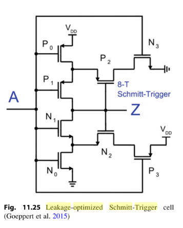
https://books.google.com/books?id=BxX_DQAAQBAJ&pg=PA337&lpg=PA337&dq=leakage+optimized+schmitt+trigger&source=bl&ots=SpqKp_p2WK&sig=ACfU3U13AjqgaLMWrsxbKil79lsI4L6vKA&hl=en&sa=X&ved=2ahUKEwiN3NiZ0YXpAhUMP60KHeLEAGoQ6AEwCXoECAoQAQ#v=onepage&q=leakage optimized schmitt trigger&f=false@NeverDie said in 💬 The Harvester: ultimate power supply for the Raybeacon DK:
but maybe some other nmos would.
... and I think I may have just now found that mosfet.
According to simulation, this oscillator consumes less than 25 picoamps at all times if running at 350 millivolts:
In fact, with higher resistor values, it will oscillate at even lower currents than that. Thus, even a solar cell in extremely dim light should be able to power it. Also nice: the same circuit runs at higher voltages if you want/need a larger voltage swing.I think I'll order the parts and build it. Wish me luck!
-
@NeverDie said in 💬 The Harvester: ultimate power supply for the Raybeacon DK:
but maybe some other nmos would.
... and I think I may have just now found that mosfet.
According to simulation, this oscillator consumes less than 25 picoamps at all times if running at 350 millivolts:
In fact, with higher resistor values, it will oscillate at even lower currents than that. Thus, even a solar cell in extremely dim light should be able to power it. Also nice: the same circuit runs at higher voltages if you want/need a larger voltage swing.I think I'll order the parts and build it. Wish me luck!
@NeverDie The circuit looks like a parametric oscillator indeed, and it is cool! What I like about it (of course, if I get it right) is that it employs only one transistor model, and those gigohm resistors are maintaining the current consumption really low. For this reason there is no need to carefully select the transistors - everything that has appropriate gate threshold value should work just fine.
On the other hand, it might happen that if you need it to work at higher frequency you will have to lower resistance of the R1-R3 and thus increase the current consumption.
BTW, accordingly to datasheet those particular FETs has quite high D-S leakage up to 1 µA. But again, should not be an issue. Perhaps, while you're here and have tools to measure picoamps, you might be interested to grab a couple of those Femto N-FETs or other officially low leakage transistors, just to compare them to others. In particular, put them against a usual FET in the super-cutoff state, i.e. when supplying negative gate-source voltage.
And, of course, I wish you best of luck with this experiment :biohazard_sign: and look forward for your updates! :hand_with_index_and_middle_fingers_crossed:
-
@NeverDie The circuit looks like a parametric oscillator indeed, and it is cool! What I like about it (of course, if I get it right) is that it employs only one transistor model, and those gigohm resistors are maintaining the current consumption really low. For this reason there is no need to carefully select the transistors - everything that has appropriate gate threshold value should work just fine.
On the other hand, it might happen that if you need it to work at higher frequency you will have to lower resistance of the R1-R3 and thus increase the current consumption.
BTW, accordingly to datasheet those particular FETs has quite high D-S leakage up to 1 µA. But again, should not be an issue. Perhaps, while you're here and have tools to measure picoamps, you might be interested to grab a couple of those Femto N-FETs or other officially low leakage transistors, just to compare them to others. In particular, put them against a usual FET in the super-cutoff state, i.e. when supplying negative gate-source voltage.
And, of course, I wish you best of luck with this experiment :biohazard_sign: and look forward for your updates! :hand_with_index_and_middle_fingers_crossed:
@Mishka I tried looking into the ultra low leakage Fets, like the femtofet, but they are just impossibly small:

If you know of any that are of a more manageable size, please do let me know. Partly it's just very tiny to handle, but also with the pads so incredibly close, I'm afraid there might be leakage outside the chip due to their close proximity.
I'm actually quite keen to try the Vishay SiP32431/2, but digikey and mouser don't have the larger package size (SC70-6) in stock, just the very small size packages. When that changes, I'll buy some to try. If there's some other source, I could try that.
-
@NeverDie The circuit looks like a parametric oscillator indeed, and it is cool! What I like about it (of course, if I get it right) is that it employs only one transistor model, and those gigohm resistors are maintaining the current consumption really low. For this reason there is no need to carefully select the transistors - everything that has appropriate gate threshold value should work just fine.
On the other hand, it might happen that if you need it to work at higher frequency you will have to lower resistance of the R1-R3 and thus increase the current consumption.
BTW, accordingly to datasheet those particular FETs has quite high D-S leakage up to 1 µA. But again, should not be an issue. Perhaps, while you're here and have tools to measure picoamps, you might be interested to grab a couple of those Femto N-FETs or other officially low leakage transistors, just to compare them to others. In particular, put them against a usual FET in the super-cutoff state, i.e. when supplying negative gate-source voltage.
And, of course, I wish you best of luck with this experiment :biohazard_sign: and look forward for your updates! :hand_with_index_and_middle_fingers_crossed:
@Mishka said in 💬 The Harvester: ultimate power supply for the Raybeacon DK:
For this reason there is no need to carefully select the transistors - everything that has appropriate gate threshold value should work just fine.
You've highlighted an essential point, which is what I too had thought, and yet the simulations (and I'm using the SPICE models provided by the manufacturers of the MOSFET parts) indicate that its much easier to get some NFETs than others to oscillate in this particular kind of circuit. Give it a try yourself and see. And it turns out Vgs(th) alone is not a good predictor. Then it seemed Rds(on) was a good predictor, but I seem to have just recently found a counter-example to that. Let me know if you have any insight. It would be good to know what what makes for a good MOSFET pick. I hope it's not just a reflection of how good or bad the component models are. That is a big reason why I want to build something right away: to see if it's true or whether the simulations are poor fidelity. If the latter, hopefully not all of them are, and maybe there are some red flags I/we can identify in advance as to which models might be good and which not. Or, failing that, maybe some manufacturers do a better modeling job than others, and knowing in advance who makes good models would steer me toward picking their mosfets.
Unfortunately, one un-related finding I've discovered about this circuit is that high gigaohm resistors seem to be quite expensive! Who'd have thought that about resistors? I had assumed they would be dirt cheap, but above about 1 or 2 gigaohm the part price starts to rapidly rise. :anguished:
Anyhow, from a practical standpoint, I'd rather not rely on high gigaohm resistances, because if those are used then suddenly the leakiness of everything (PCBs, insulation, practically everything) will likely become more of a factor in how the circuit behaves, and mainstream fabrication isn't geared up for that.
So I'll try building these circuits, even if I have to deadbug them, to answer the question about simulation fidelity, but then I'm hoping the next step will be low leakage components and/or leakage suppression by circuit design, such as DLS, because maybe then regular fabrication methods and materials will be good enough, and we'd be spared the cost of expensive resistors too. :face_with_rolling_eyes:
P.S. I found a source that has SIP32431DR3T1GE3 in stock, so I ordered some. I think my highest hopes are now with that. Unfortunately, there are no SPICE models of it, but maybe tweaking down the DS leakage and GS leakage of a pre-built model for a different PFET would approximate it? After all, Vishay did say (in their response that I posted earlier above) that it is as largely a PFET. I also ordered some FemtoFETs, despite my reservations (above) about their incredibly small size--maybe we'll uncover DIY-friendly way to cope with that.
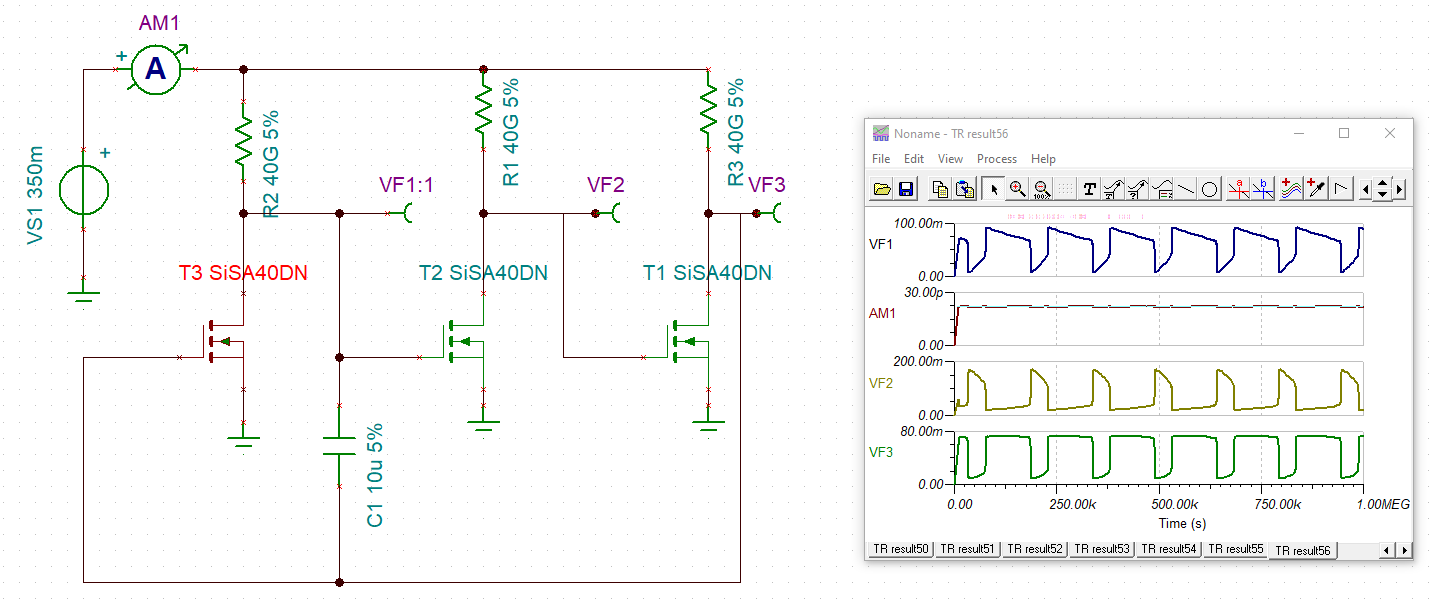
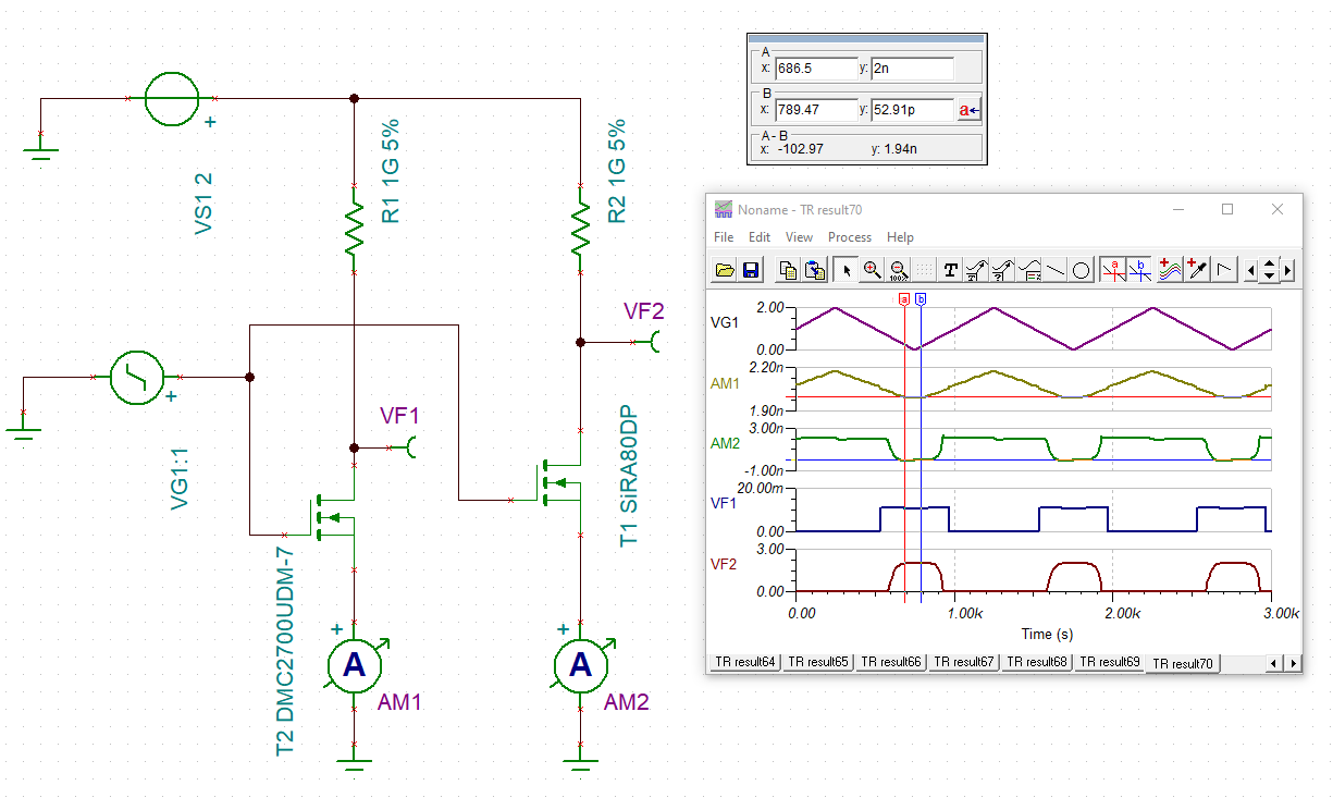
Edit1: Looking into it more, one of the differences between the nfet's is that some can oscillate when the resistor values are 1G and above, whereas others cannot. For instance, DMC2700UDM-7 is one that can't seem to manage it. It's "problem" seems to be that the voltage dropped across it is a lot less than the input voltage. Now, it does have a low RDS(on), but so does SiSA40DN (see circuit above), but SiSA40DN has a higher threshold voltage. Not sure if there are other factors, but apparently even with less of a current flowing through it, due to the higher resistor values, somehow SiSA40DN manages to not switch until more of a voltage develops across it. Not sure how to express that--maybe you do?--but I think that may be the crux of what makes it better in this type of circuit, because it's the voltage dropped across it which is what triggers the next nfet in the sequence. It would appear that there's some kind of relation between the VGS curve and the RDS curve which makes one NFET better than the other for this type of circuit. And when you think about it, the resistance across the nfet has to be a lot more than 1G in order for most of the voltage to be dropped across it, which means that the switching needs to happen at less than VG(th), which it does. So, perhaps it's the bias current flowing into the gate which is the critical factor? That would be controlled by the resistor value. Maybe DMC2700UDM-7 needs more bias current than SiSA40DN does, and so that's why it works only with resistors less than 1Gohm? I'm not sure whether or not there's even a datasheet entry for mosfet gate bias current (would it be gate resistance? gate capacitance? Total gate charge? Some combination of those? Is maybe gate-drain leakage a factor? Something else?), though I know for op-amps it's called out explicitly as an important figure of merit. Hmmm......
Edit2: It's confirmed. By placing simulator ammeters inline with the gates of the mosfets, it's clear that the gate on each DMC2700UDM-7 consumes 73pa in steady state, whereas the gate on SiSA40DN consumes less than 3pa. Also, during the transitions, the gate on DMC2700UDM-7 consumes around 900pa, whereas the gate on SiSA40DN consumes about half that. So, maybe that has something to do with with why DMC2700UDM-7 can't oscillate with gigaohm reistances? And, if so, what entry on the datasheet reflects that? Curiously, the source gate leakage in the reverse direction is far worse with the SiSA40DN (about 30pa) than with the DMC2700UDM-7 (less than 1pa).
-
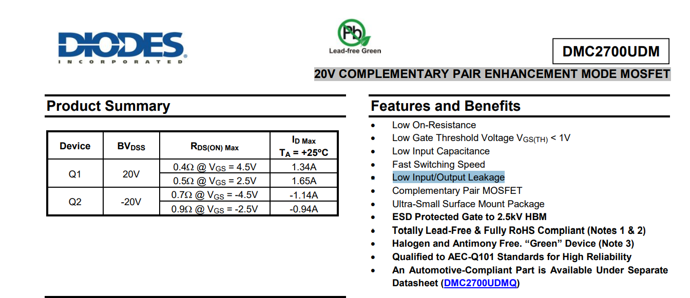
I think I likely found the smoking gun difference between the two mosfets. What's peculiar about them is that their Idss and Igss datasheet entries have values that are flipped with respect to one another:
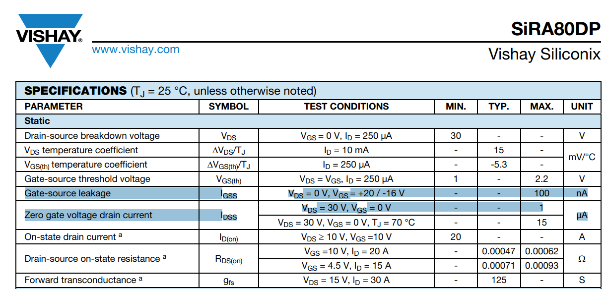
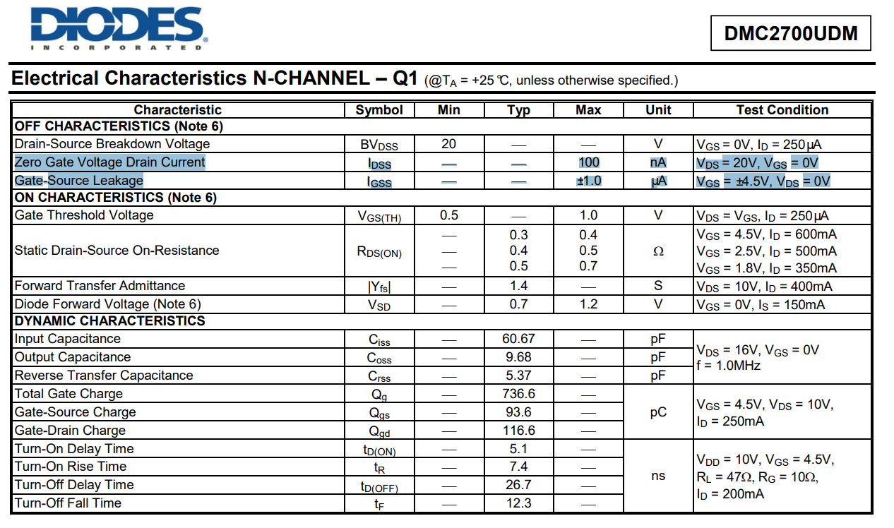
I think I trust the Diodes Incorporated datasheet a bit more, because they supply more detailt about the issue:
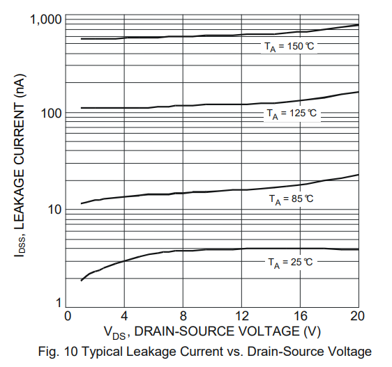
whereas the Vishay datasheet is otherwise silent about it. If Vishay actually had a great DS leakage figure, wouldn't it have mentioned it in its intro paragraph? But no, it wasn't called out anywhere else in the Vishay datasheet.The DS leakage of the DMC2700UDM-7 plays out in the simulation to its detriment, and I think it probably explains why the voltage drop across it is so low compared to the Vishay mosfet:
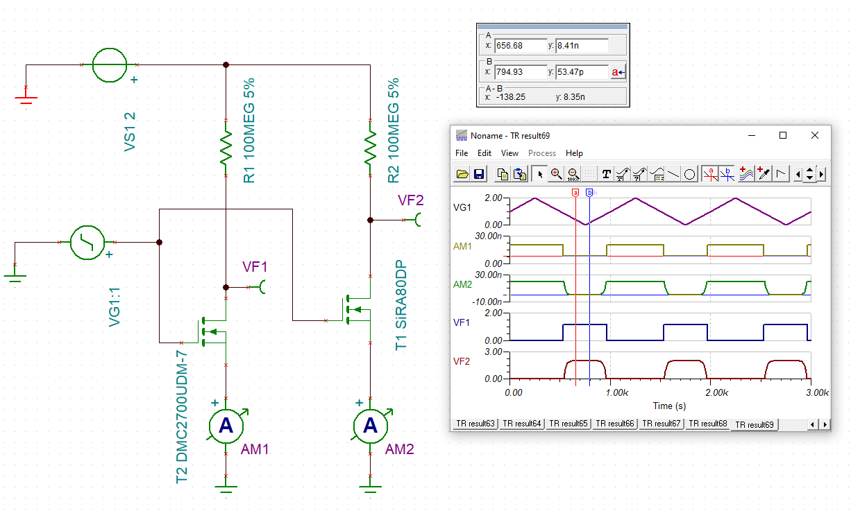
With the 1Gigaohm resistor in place, the DMC2700UDM-7 is showing a DS leakage of 2na, versus just 53pa for the Vishay. Quite a difference! The differences in voltages across the mosfets is equally striking (11mv vs. a full 2v), and, given the above test setup, I presume the difference is entirely due to the difference in leakage currents. With the gigaohm resistor, virtually all of the current entering the Diode's mosphet is lost due to leakage, leaving almost no voltage left.I just hope the Vishay lives up to its billing and that their product delivers on what their SPICE model promises. I hope it's not a confusion that's been written into Vishay's SPICE model. However, right now, if I'm reading and interpreting it right, it looks as though the Vishay SPICE model results don't correlate with what the Vishay datasheet says: according to the Vishay datasheet, it appears that the Vishay DS leakage should actually be worse than the Diodes Incorporated mosphet's, but (as shown above) the Vishay SPICE simulation results don't show that at all. Instead, far from that, according to the Vishay SPICE model, the Vishay appears to be 2 orders of magnitude better. Meh, I'll be happy if it's so, but I'm starting to doubt it. Unfortunately, the much worse Vishay datasheet entry was measured at 30v, so it's not directly comparable to the Diodes's 20v, so maybe....? For sure, I'll be testing Idss on the real Vishay product, and then we'll know for certain.
-
As a "Plan B," I tried simulating a ring oscillator using super-beta transistors, and the results are turning out surprisingly well:
The downside, as before, is that it relies on high gigaohm resistors to achieve the low current consumption, but the waveform nonetheless looks pretty sharp, and the frequency can be adjusted faster or slower by the capacitor selection. According to the simulation, at 2.5v, this one consumes less than 800pa. And, as you would expect, current consumption is less at lower voltages, but obviously then you get a less useful voltage swing.
Mouser sells some 1206 SMD 10Gohm resistors at $1.18 each (quantity 10), but at 25% tolerance. I expect even a 25% tolerance is probably acceptable for a circuit like this, and so resistor cost need not be a show stopper.
I may actually end up preferring this circuit over the others. It seems like it may be a "good enough" fit for the solar cell that I'm using. :)
By increasing the ohms on the resistors feeding the resistor bases, you can increase the swing voltage even more:
That might be useful for using this circuit to control some other circuit.To date I've had no luck getting any of the leakage supression circuits to work in simulation. It would help a lot if someone reading this could suggest a circuit to try--something more detailed than what's presented in the academic papers we've already identified.
-
@Mishka said in 💬 The Harvester: ultimate power supply for the Raybeacon DK:
For this reason there is no need to carefully select the transistors - everything that has appropriate gate threshold value should work just fine.
You've highlighted an essential point, which is what I too had thought, and yet the simulations (and I'm using the SPICE models provided by the manufacturers of the MOSFET parts) indicate that its much easier to get some NFETs than others to oscillate in this particular kind of circuit. Give it a try yourself and see. And it turns out Vgs(th) alone is not a good predictor. Then it seemed Rds(on) was a good predictor, but I seem to have just recently found a counter-example to that. Let me know if you have any insight. It would be good to know what what makes for a good MOSFET pick. I hope it's not just a reflection of how good or bad the component models are. That is a big reason why I want to build something right away: to see if it's true or whether the simulations are poor fidelity. If the latter, hopefully not all of them are, and maybe there are some red flags I/we can identify in advance as to which models might be good and which not. Or, failing that, maybe some manufacturers do a better modeling job than others, and knowing in advance who makes good models would steer me toward picking their mosfets.
Unfortunately, one un-related finding I've discovered about this circuit is that high gigaohm resistors seem to be quite expensive! Who'd have thought that about resistors? I had assumed they would be dirt cheap, but above about 1 or 2 gigaohm the part price starts to rapidly rise. :anguished:
Anyhow, from a practical standpoint, I'd rather not rely on high gigaohm resistances, because if those are used then suddenly the leakiness of everything (PCBs, insulation, practically everything) will likely become more of a factor in how the circuit behaves, and mainstream fabrication isn't geared up for that.
So I'll try building these circuits, even if I have to deadbug them, to answer the question about simulation fidelity, but then I'm hoping the next step will be low leakage components and/or leakage suppression by circuit design, such as DLS, because maybe then regular fabrication methods and materials will be good enough, and we'd be spared the cost of expensive resistors too. :face_with_rolling_eyes:
P.S. I found a source that has SIP32431DR3T1GE3 in stock, so I ordered some. I think my highest hopes are now with that. Unfortunately, there are no SPICE models of it, but maybe tweaking down the DS leakage and GS leakage of a pre-built model for a different PFET would approximate it? After all, Vishay did say (in their response that I posted earlier above) that it is as largely a PFET. I also ordered some FemtoFETs, despite my reservations (above) about their incredibly small size--maybe we'll uncover DIY-friendly way to cope with that.
Edit1: Looking into it more, one of the differences between the nfet's is that some can oscillate when the resistor values are 1G and above, whereas others cannot. For instance, DMC2700UDM-7 is one that can't seem to manage it. It's "problem" seems to be that the voltage dropped across it is a lot less than the input voltage. Now, it does have a low RDS(on), but so does SiSA40DN (see circuit above), but SiSA40DN has a higher threshold voltage. Not sure if there are other factors, but apparently even with less of a current flowing through it, due to the higher resistor values, somehow SiSA40DN manages to not switch until more of a voltage develops across it. Not sure how to express that--maybe you do?--but I think that may be the crux of what makes it better in this type of circuit, because it's the voltage dropped across it which is what triggers the next nfet in the sequence. It would appear that there's some kind of relation between the VGS curve and the RDS curve which makes one NFET better than the other for this type of circuit. And when you think about it, the resistance across the nfet has to be a lot more than 1G in order for most of the voltage to be dropped across it, which means that the switching needs to happen at less than VG(th), which it does. So, perhaps it's the bias current flowing into the gate which is the critical factor? That would be controlled by the resistor value. Maybe DMC2700UDM-7 needs more bias current than SiSA40DN does, and so that's why it works only with resistors less than 1Gohm? I'm not sure whether or not there's even a datasheet entry for mosfet gate bias current (would it be gate resistance? gate capacitance? Total gate charge? Some combination of those? Is maybe gate-drain leakage a factor? Something else?), though I know for op-amps it's called out explicitly as an important figure of merit. Hmmm......
Edit2: It's confirmed. By placing simulator ammeters inline with the gates of the mosfets, it's clear that the gate on each DMC2700UDM-7 consumes 73pa in steady state, whereas the gate on SiSA40DN consumes less than 3pa. Also, during the transitions, the gate on DMC2700UDM-7 consumes around 900pa, whereas the gate on SiSA40DN consumes about half that. So, maybe that has something to do with with why DMC2700UDM-7 can't oscillate with gigaohm reistances? And, if so, what entry on the datasheet reflects that? Curiously, the source gate leakage in the reverse direction is far worse with the SiSA40DN (about 30pa) than with the DMC2700UDM-7 (less than 1pa).
@NeverDie In SPICE the ring oscillator works just fine. I don't see why it may be hard to have it oscillating with any FET. However, due to the fact it's perfectly balanced (at least in it's current form) across all the three transistors it may be somewhat reluctant to start.
Here is how I get it in the light of the power consumption. For convenience, I've re-enumerated all components left to right.
Phase 1. I'm not going to cover the circuit boot and will start at the moment when the Q3 is closed. In the closed state VF3=0 it will tie the Q1 gate and the bottom pole of C1 to the ground. The Q1 is closed, and the C1 will be charging via R1 resistor. The R1 will set the charge time for C1.
At the same time, due to the closed Q3 the voltage source will be grounded via R3 and this results in extra leakage Vin/R3. At this phase, the overall current consumption will be about
I ≈ Vin/R2 + Vin/R3Phase 2. The phase 1 will last until C1 will be charged to the Q2 gate threshold voltage. After that, the Q2 which was previously open due to the C1 voltage drop, closes, and this will tie VF2 to the ground and open the Q3.
The opened Q3 will shift ground level for the C1 thus doubling the VF1 voltage. The C1 will start discharging down to zero until VF1 won't balance VF3. Actually, the C1 it will be charged from the opposite side via R3. The R3 defines period of the stage 2. Consumption current should be about the same
I ≈ Vin/R2 + Vin/R3. Please note, since the Q2 is not participating in C1 charge/discharge it should be safe to keep R2 resistance much higher than R1 and R2, like 300g or so, and decrease the circuit consumption.However, it seems slightly more complicated than that. Due to FETs non-linearity, at marginal gate voltages there is some drain–source resistance. Despite the Q1 is open with VF3 voltage, it's not enough to have the C1 grounded, and this is why the circuit works at all. Instead, both C1 and the voltage source will be leaking via the Q1. While voltage source is limited by R2, the leakage for C1 may be quite high and require extra attention. Luckily, this is not true for the SiSA40DN - the C1 slowly discharges via Q1 and this compensates for leakage from the voltage source via R1.
Repeat. Upon C1 discharge it's going to close Q2 and raise gate voltage on Q3. The Q3 opens, VF3 voltage drops, then Q1 closes too, and the C1 starts charging back again.
Well, as for an astable oscillator the circuit looks cool, definitely would be interesting to build. But for energy harvesting purposes I'd prefer some UB40M variation - IMHO it's much cleaner from the point of parasitic leakages. Especially if taking in account those leakage optimization techniques like we've seen for the super cutoff gates.
-
@NeverDie In SPICE the ring oscillator works just fine. I don't see why it may be hard to have it oscillating with any FET. However, due to the fact it's perfectly balanced (at least in it's current form) across all the three transistors it may be somewhat reluctant to start.
Here is how I get it in the light of the power consumption. For convenience, I've re-enumerated all components left to right.
Phase 1. I'm not going to cover the circuit boot and will start at the moment when the Q3 is closed. In the closed state VF3=0 it will tie the Q1 gate and the bottom pole of C1 to the ground. The Q1 is closed, and the C1 will be charging via R1 resistor. The R1 will set the charge time for C1.
At the same time, due to the closed Q3 the voltage source will be grounded via R3 and this results in extra leakage Vin/R3. At this phase, the overall current consumption will be about
I ≈ Vin/R2 + Vin/R3Phase 2. The phase 1 will last until C1 will be charged to the Q2 gate threshold voltage. After that, the Q2 which was previously open due to the C1 voltage drop, closes, and this will tie VF2 to the ground and open the Q3.
The opened Q3 will shift ground level for the C1 thus doubling the VF1 voltage. The C1 will start discharging down to zero until VF1 won't balance VF3. Actually, the C1 it will be charged from the opposite side via R3. The R3 defines period of the stage 2. Consumption current should be about the same
I ≈ Vin/R2 + Vin/R3. Please note, since the Q2 is not participating in C1 charge/discharge it should be safe to keep R2 resistance much higher than R1 and R2, like 300g or so, and decrease the circuit consumption.However, it seems slightly more complicated than that. Due to FETs non-linearity, at marginal gate voltages there is some drain–source resistance. Despite the Q1 is open with VF3 voltage, it's not enough to have the C1 grounded, and this is why the circuit works at all. Instead, both C1 and the voltage source will be leaking via the Q1. While voltage source is limited by R2, the leakage for C1 may be quite high and require extra attention. Luckily, this is not true for the SiSA40DN - the C1 slowly discharges via Q1 and this compensates for leakage from the voltage source via R1.
Repeat. Upon C1 discharge it's going to close Q2 and raise gate voltage on Q3. The Q3 opens, VF3 voltage drops, then Q1 closes too, and the C1 starts charging back again.
Well, as for an astable oscillator the circuit looks cool, definitely would be interesting to build. But for energy harvesting purposes I'd prefer some UB40M variation - IMHO it's much cleaner from the point of parasitic leakages. Especially if taking in account those leakage optimization techniques like we've seen for the super cutoff gates.
@Mishka said in 💬 The Harvester: ultimate power supply for the Raybeacon DK:
But for energy harvesting purposes I'd prefer some UB40M variation - IMHO it's much cleaner from the point of parasitic leakages. Especially if taking in account those leakage optimization techniques like we've seen for the super cutoff gates.
That's what I originally thought as well, except I haven't been able to get any of the leakage optimization techniques to work. That's what has driven me down the current path of seeing if I might be able to do anything worthwhile with simpler circuits like these. I didn't want to take this detour, but at least I could get them to "work," at least nominally. If you can see how to implement the leakage optimizations, and get them working in simulation, then that would be great. I'd love to see it. I'd much rather use some kind of smart leakage suppression circuitry than rely on super high gigaohm resistances. I've tried, but I just haven't been able to get any working circuits with that approach. TL;DR: I'm stuck wrt leakage suppression.
So, if you're able to make some headway on leakage suppression, I'd be more than happy to circle back to it.
BTW, a couple of interesting things about the NPN ring oscillator are worth mentioning:
- It works over a wide voltage range: from 300mv up to 20v.
- In contrast to the NFET ring oscillator, where when an NFET is "OFF", it continues to leak current, in the NPN ring oscillator, when the NPN is "OFF", it leaks almost no current at all--maybe just a couple picoamps or less.
Here are the waveforms and currents drawn when it's powered with just 300mv:
As you can see, in this particular example, where it is using "only" 10G resistors, it's drawing a sum total current of less than 70pa at all times.
-
@Mishka said in 💬 The Harvester: ultimate power supply for the Raybeacon DK:
But for energy harvesting purposes I'd prefer some UB40M variation - IMHO it's much cleaner from the point of parasitic leakages. Especially if taking in account those leakage optimization techniques like we've seen for the super cutoff gates.
That's what I originally thought as well, except I haven't been able to get any of the leakage optimization techniques to work. That's what has driven me down the current path of seeing if I might be able to do anything worthwhile with simpler circuits like these. I didn't want to take this detour, but at least I could get them to "work," at least nominally. If you can see how to implement the leakage optimizations, and get them working in simulation, then that would be great. I'd love to see it. I'd much rather use some kind of smart leakage suppression circuitry than rely on super high gigaohm resistances. I've tried, but I just haven't been able to get any working circuits with that approach. TL;DR: I'm stuck wrt leakage suppression.
So, if you're able to make some headway on leakage suppression, I'd be more than happy to circle back to it.
BTW, a couple of interesting things about the NPN ring oscillator are worth mentioning:
- It works over a wide voltage range: from 300mv up to 20v.
- In contrast to the NFET ring oscillator, where when an NFET is "OFF", it continues to leak current, in the NPN ring oscillator, when the NPN is "OFF", it leaks almost no current at all--maybe just a couple picoamps or less.
Here are the waveforms and currents drawn when it's powered with just 300mv:
As you can see, in this particular example, where it is using "only" 10G resistors, it's drawing a sum total current of less than 70pa at all times.
@NeverDie Regarding components selection - unfortunately, that's true, too few manufacturers provide that data in a table to compare and select from. So far we have the FemtoFET series from Texas, the FETs listed in the Nexperia's AN90009 paper, and the ALD FETs. General recommendations for a low-lakage FET may be:
- Higher gate–source bias voltage. Obviously, the higher voltage required to turn a FET on - the more resistance between gate and source, and the less leakage.
- Higher source-drain resistance when on. It simply means the FET will have higher resistance when closed too.
- Protection diode may also cause some leakage.
However, an attempt to select low-leakage FETs using these recommendations will certainly fail. It rather seem more depends on specs a manufacturer tries to warrant. For example, in theory high drain-source voltage may imply lower leakage at low voltages. But usually lower power transistors are leaking less.
Such, all Vishay specs I've read for more or less matching transistors mention exactly the same values for GS and DS leakage. Similarly, all ALD transistors have very low leakage because the ALD is working hard to manufacture them so. But I admit, for unknown reason any of those low-leakage FETs are ridiculously small, it's very rare when any dimension is bigger than 1mm.
Looks like if we really want it low, we must accept the size. On the other hand, some youtubers do solder even 008004 which are way smaller.
Alternative way is to choose a couple of transistors and measure them. I think that 1µA leakage from datasheet will barely go over 10nA in practice, so your choice should be just fine.
BTW, SPICE models usually operate with physical dimension, so should be accurate enough when it comes to comparing leakage of different items.
-
@Mishka said in 💬 The Harvester: ultimate power supply for the Raybeacon DK:
But for energy harvesting purposes I'd prefer some UB40M variation - IMHO it's much cleaner from the point of parasitic leakages. Especially if taking in account those leakage optimization techniques like we've seen for the super cutoff gates.
That's what I originally thought as well, except I haven't been able to get any of the leakage optimization techniques to work. That's what has driven me down the current path of seeing if I might be able to do anything worthwhile with simpler circuits like these. I didn't want to take this detour, but at least I could get them to "work," at least nominally. If you can see how to implement the leakage optimizations, and get them working in simulation, then that would be great. I'd love to see it. I'd much rather use some kind of smart leakage suppression circuitry than rely on super high gigaohm resistances. I've tried, but I just haven't been able to get any working circuits with that approach. TL;DR: I'm stuck wrt leakage suppression.
So, if you're able to make some headway on leakage suppression, I'd be more than happy to circle back to it.
BTW, a couple of interesting things about the NPN ring oscillator are worth mentioning:
- It works over a wide voltage range: from 300mv up to 20v.
- In contrast to the NFET ring oscillator, where when an NFET is "OFF", it continues to leak current, in the NPN ring oscillator, when the NPN is "OFF", it leaks almost no current at all--maybe just a couple picoamps or less.
Here are the waveforms and currents drawn when it's powered with just 300mv:
As you can see, in this particular example, where it is using "only" 10G resistors, it's drawing a sum total current of less than 70pa at all times.
@NeverDie said in 💬 The Harvester: ultimate power supply for the Raybeacon DK:
a couple of interesting things about the NPN ring oscillator are worth mentioning:
It works over a wide voltage range: from 300mv up to 20v.
In contrast to the NFET ring oscillator, where when an NFET is "OFF", it continues to leak current, in the NPN ring oscillator, when the NPN is "OFF", it leaks almost no current at all--maybe just a couple picoamps or less.Yeah, it is impressive, no doubt. I'm not confident with so low-power circuits and were taught that MOSFETs are leaking less, and BJTs are requiring more current to drive. But this discussion disregards it all, at least when it comes to discretes :-D
-
While i wait for parts to arrive, I crafted a simple "Hello World" variant of the circuit to blink some LED's so as to have an easy first test ready when setting up real hardware:
-
Because I didn't have 1000uF capacitors laying about, I built a variant to the test circuit (the one directly above) to match what I did have on hand. Bottom line: it works, and,equally important, AFAIK it seems to work in the way that the simulation predicts. :+1:
In order to light the LEDs, the test circuit was deliberately designed to draw many orders of magnitude more current than the ultimate low energy target oscillator. Purely out of curiosity I hooked it up to various solar panels anyway just to see how it might behave under different lighting conditions. Not surprisingly, when there's adequate power, it oscillates and does what you would expect. However, when starved of enough current, it stops oscillating but nonetheless lights all three LEDs with whatever current it does have. Then, if the lighting improves, it will gradually start oscillating again. Neither here nor there, but, at least conceptually, I'd rather that it instead conserved its energy and didn't light any LEDs at all when it couldn't oscillate rather than light all of them. That way maybe it would be able to store up enough energy to resume oscillation, even if only briefly. That said, I don't expect this to be much of an issue in the ultimate target circuit, because its oscillation energy requirements should be many orders of magnitude lower, but at least now I know it's something I should probably look out for, just to be sure.
-
@NeverDie Cool! :+1:
A supervisory circuit will be needed between the store and the load anyway. BTW, most of ultra-low power supervisors will consume tens of nanoamps. Does it mean it has to be a low leaking FET? :-)
@Mishka said in 💬 The Harvester: ultimate power supply for the Raybeacon DK:
@NeverDie Cool! :+1:
A supervisory circuit will be needed between the store and the load anyway. BTW, most of ultra-low power supervisors will consume tens of nanoamps. Does it mean it has to be a low leaking FET? :-)
That's why I'm hoping that this will fill the role of supervisor:
https://www.ablic.com/en/doc/datasheet/photo_ic/S5470_E.pdf
The datasheet says it consumes <= 100pa of current, which beats even the UB20 (after the UB20's leakage currents are accounted for). More importantly, unlike the UB20, it's well stocked at both Digikey and Mouser, so getting it isn't problem. Unfortunately, AFAIK, there's no SPICE model for it. I'm hoping that something designed to detect faint signals won't be overly interfering, but I don't think we can know for sure without giving it a test drive. How it behaves during a detection event might also matter.If the Vishay load switch could function as a supervisor, then maybe it would be even better. It seems worth looking into. For one thing, it's cheaper. Maybe it might even consume less current, either before or during a detection event.
Ultimately, the challenge may be how well the supervisor reacts to a very slowly rising current or voltage. All of the gigaohm oscillator circuits that are the current focus are current starved, and probably for that reason none of the oscillator circuits appears to switch very quickly. We know, for example, that a generic schmitt trigger tends to draw a lot of power near the trigger point. You mentioned a FET, but I suspect it would have the same issue as a schmitt trigger.
Unless you can think of a way to somehow roll-your-own ultra low power supervisor, I'm not aware of anything else. I suspect that maybe the Michigan team that built the Cortex M0 with the ultra tiny solar cell could easily beat both the ABLIC and Vishay supervisors--I'm still gobsmacked by what the Michigan team accomplished-- but at the moment I don't understand how to do the kind of leakage supression that's the foundation of what the Michigan team did. On my one and only attempt, after toying around with it, I was able to get one simulation that seemed to oscillate under very narrow conditions without meaningful leakage, and at first that gave me some hope. However, at the time I didn't see a way to extend that tiny, somewhat dubuious success toward anything useful. Having read the Michigan paper, can you get a leakage supression simulation working, either from their schematic or from one of the other papers? If so, that would be enormously helpful. I could post the simulation that I tried if you wanted to take a stab at it. It's not much, but pretty much anything, even an unremarkable crippled anything, is more than what typically gets published in the academic papers.
As for me, my next step is to fabricate/install some teflon mounts for my first attempt at the target circuit to rest on. I also need to build some fancier op-amp circuits to take measurements. It's a bit exotic, and maybe there's a better way, but at the moment this seems to me like the most promising path toward getting a verified working POC, or at least the low energy oscillator part of it. I don't think the SPICE simulations even attempt to account for noise, and so I have no way of judging in advance whether or not noise, at the projected ultra low power levels, might be a big or small issue or even no issue at all. I suspect it may require shielding though, and, if so, maybe that will be sufficient.
-
The TS12001 looks like it could be incredibly useful, even just by itself. It behaves like a combination voltageDetector+loadSwitch. When below the threshold voltage, it disconnects the load and cuts its quiescent current to just 100pa: https://www.mouser.com/datasheet/2/761/Semtech_06142018_TS12001_Rev_1.5-1371249.pdf
Edit1: Unfortunately, I can't find anywhere that has it in stock.
-
@Mishka said in 💬 The Harvester: ultimate power supply for the Raybeacon DK:
@NeverDie Cool! :+1:
A supervisory circuit will be needed between the store and the load anyway. BTW, most of ultra-low power supervisors will consume tens of nanoamps. Does it mean it has to be a low leaking FET? :-)
That's why I'm hoping that this will fill the role of supervisor:
https://www.ablic.com/en/doc/datasheet/photo_ic/S5470_E.pdf
The datasheet says it consumes <= 100pa of current, which beats even the UB20 (after the UB20's leakage currents are accounted for). More importantly, unlike the UB20, it's well stocked at both Digikey and Mouser, so getting it isn't problem. Unfortunately, AFAIK, there's no SPICE model for it. I'm hoping that something designed to detect faint signals won't be overly interfering, but I don't think we can know for sure without giving it a test drive. How it behaves during a detection event might also matter.If the Vishay load switch could function as a supervisor, then maybe it would be even better. It seems worth looking into. For one thing, it's cheaper. Maybe it might even consume less current, either before or during a detection event.
Ultimately, the challenge may be how well the supervisor reacts to a very slowly rising current or voltage. All of the gigaohm oscillator circuits that are the current focus are current starved, and probably for that reason none of the oscillator circuits appears to switch very quickly. We know, for example, that a generic schmitt trigger tends to draw a lot of power near the trigger point. You mentioned a FET, but I suspect it would have the same issue as a schmitt trigger.
Unless you can think of a way to somehow roll-your-own ultra low power supervisor, I'm not aware of anything else. I suspect that maybe the Michigan team that built the Cortex M0 with the ultra tiny solar cell could easily beat both the ABLIC and Vishay supervisors--I'm still gobsmacked by what the Michigan team accomplished-- but at the moment I don't understand how to do the kind of leakage supression that's the foundation of what the Michigan team did. On my one and only attempt, after toying around with it, I was able to get one simulation that seemed to oscillate under very narrow conditions without meaningful leakage, and at first that gave me some hope. However, at the time I didn't see a way to extend that tiny, somewhat dubuious success toward anything useful. Having read the Michigan paper, can you get a leakage supression simulation working, either from their schematic or from one of the other papers? If so, that would be enormously helpful. I could post the simulation that I tried if you wanted to take a stab at it. It's not much, but pretty much anything, even an unremarkable crippled anything, is more than what typically gets published in the academic papers.
As for me, my next step is to fabricate/install some teflon mounts for my first attempt at the target circuit to rest on. I also need to build some fancier op-amp circuits to take measurements. It's a bit exotic, and maybe there's a better way, but at the moment this seems to me like the most promising path toward getting a verified working POC, or at least the low energy oscillator part of it. I don't think the SPICE simulations even attempt to account for noise, and so I have no way of judging in advance whether or not noise, at the projected ultra low power levels, might be a big or small issue or even no issue at all. I suspect it may require shielding though, and, if so, maybe that will be sufficient.
@NeverDie said in 💬 The Harvester: ultimate power supply for the Raybeacon DK:
Unless you can think of a way to somehow roll-your-own ultra low power supervisor, I'm not aware of anything else. I suspect that maybe the Michigan team that built the Cortex M0 with the ultra tiny solar cell could easily beat both the ABLIC and Vishay supervisors--I'm still gobsmacked by what the Michigan team accomplished-- but at the moment I don't understand how to do the kind of leakage supression that's the foundation of what the Michigan team did. On my one and only attempt, after toying around with it, I was able to get one simulation that seemed to oscillate under very narrow conditions without meaningful leakage, and at first that gave me some hope. However, at the time I didn't see a way to extend that tiny, somewhat dubuious success toward anything useful. Having read the Michigan paper, can you get a leakage supression simulation working, either from their schematic or from one of the other papers? If so, that would be enormously helpful. I could post the simulation that I tried if you wanted to take a stab at it. It's not much, but pretty much anything, even an unremarkable crippled anything, is more than what typically gets published in the academic papers.
IMHO this is the promising direction to go. I haven't analyzed the circuits yet, but the super cut-off idea is dead simple - instead of grounding transistor gates, they have to be under-driven with a negative voltage. This should effectively remove free electrons from the depletion region and hence minimize drain–source leakage. Unfortunately, this requires to maintain an additional negative power source which may draw it's own current to operate. The overhead may be to expensive for a circuit with few gates, but seems well worth it for a processor core with thousands of transistors. What's good, is that this technique clearly separates optimization from the logic. In SPICE it might be easily simulated with a second voltage source, for example, at -0.1V. BTW, for the same reason the higher Vth - the lower DS leakage should be expected.
I'm thinking about building the UB40M alike circuit with any transistors. Well, the FemtoFET series is very small indeed. But size of the biggest package codename F5 is 0.73x1.49 mm which is roughly the same size as 0603 components. With proper PCB footprint soldering them should not be an issue. All in all, what must we expect from a modern high performing transistor?
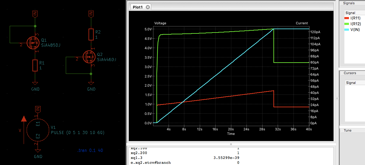
Unfortunately, my ngspice doesn't work well with the Level 7 model the TI provides. So to have anything tangible to play with I've noticed a complimentary pair from Vishay, Vth=2.5V, Vds=150V: SiA485DJ (P-channel) and SiA446DJ (N-channel). PowerPak SC-70 package also looks appealing - 2x2 mm will help save PCB space, but still not microscopic.
Unfortunately, the P-MOS has no SPICE model, damn it. I'll try to replace it with Si1411DH which parameters looks very close to the SiA485DJ, and there are SPICE models for it.
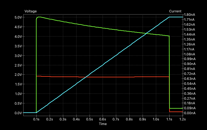
Some leakage curves for the FETs in the 0...5V range:
Interesting, that the faster raises the voltage - the more leakage occurs. For example, the same chart for 1s raise:
-
@NeverDie said in 💬 The Harvester: ultimate power supply for the Raybeacon DK:
Unless you can think of a way to somehow roll-your-own ultra low power supervisor, I'm not aware of anything else. I suspect that maybe the Michigan team that built the Cortex M0 with the ultra tiny solar cell could easily beat both the ABLIC and Vishay supervisors--I'm still gobsmacked by what the Michigan team accomplished-- but at the moment I don't understand how to do the kind of leakage supression that's the foundation of what the Michigan team did. On my one and only attempt, after toying around with it, I was able to get one simulation that seemed to oscillate under very narrow conditions without meaningful leakage, and at first that gave me some hope. However, at the time I didn't see a way to extend that tiny, somewhat dubuious success toward anything useful. Having read the Michigan paper, can you get a leakage supression simulation working, either from their schematic or from one of the other papers? If so, that would be enormously helpful. I could post the simulation that I tried if you wanted to take a stab at it. It's not much, but pretty much anything, even an unremarkable crippled anything, is more than what typically gets published in the academic papers.
IMHO this is the promising direction to go. I haven't analyzed the circuits yet, but the super cut-off idea is dead simple - instead of grounding transistor gates, they have to be under-driven with a negative voltage. This should effectively remove free electrons from the depletion region and hence minimize drain–source leakage. Unfortunately, this requires to maintain an additional negative power source which may draw it's own current to operate. The overhead may be to expensive for a circuit with few gates, but seems well worth it for a processor core with thousands of transistors. What's good, is that this technique clearly separates optimization from the logic. In SPICE it might be easily simulated with a second voltage source, for example, at -0.1V. BTW, for the same reason the higher Vth - the lower DS leakage should be expected.
I'm thinking about building the UB40M alike circuit with any transistors. Well, the FemtoFET series is very small indeed. But size of the biggest package codename F5 is 0.73x1.49 mm which is roughly the same size as 0603 components. With proper PCB footprint soldering them should not be an issue. All in all, what must we expect from a modern high performing transistor?
Unfortunately, my ngspice doesn't work well with the Level 7 model the TI provides. So to have anything tangible to play with I've noticed a complimentary pair from Vishay, Vth=2.5V, Vds=150V: SiA485DJ (P-channel) and SiA446DJ (N-channel). PowerPak SC-70 package also looks appealing - 2x2 mm will help save PCB space, but still not microscopic.
Unfortunately, the P-MOS has no SPICE model, damn it. I'll try to replace it with Si1411DH which parameters looks very close to the SiA485DJ, and there are SPICE models for it.
Some leakage curves for the FETs in the 0...5V range:
Interesting, that the faster raises the voltage - the more leakage occurs. For example, the same chart for 1s raise:
@Mishka Great! I'm really looking forward to it. If you can get something working in your simulator then as a cross-check I can try replicating it in the TI Tina simulator. If it works in both simulators, then I would imagine the odds are that much better that it will work in the real world with physical hardware.
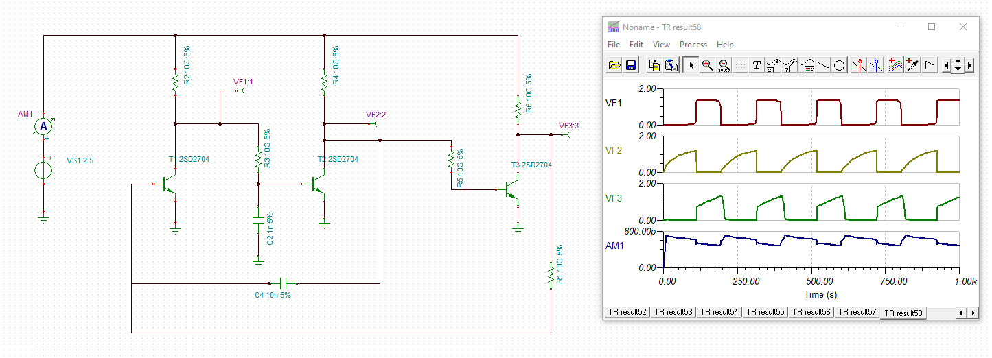
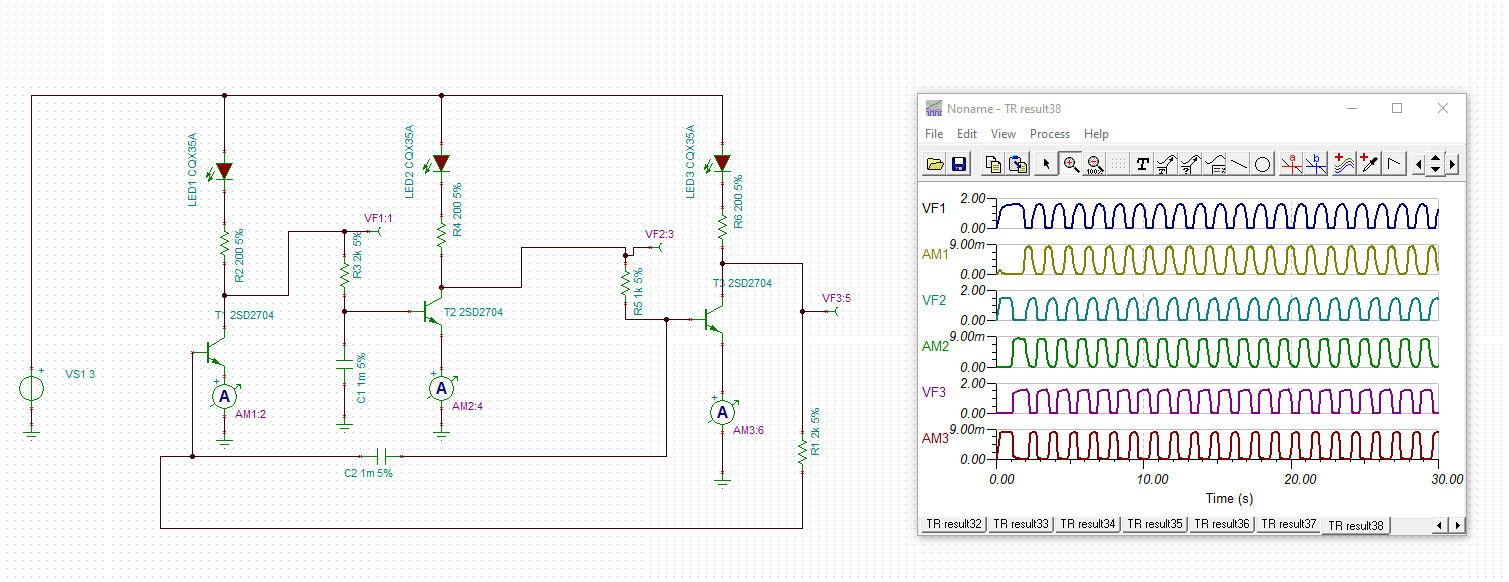
Speaking of simulation, I polished the ring oscillator circuit a bit more and, as a "virtual POC," got it to do pretty close to what I had originally aimed for:
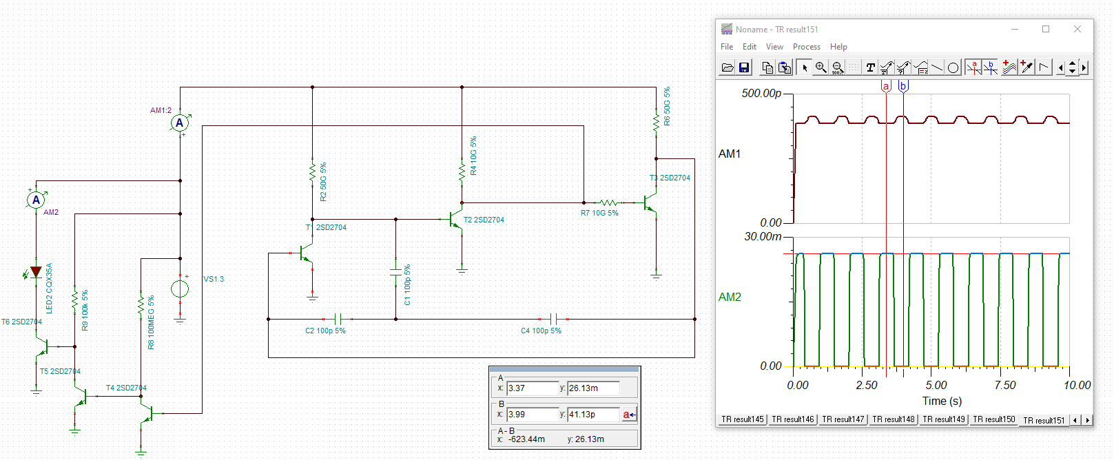
In a nutshell: 1. When the timer switches on, it drives an LED (which represents a load ) with with up to 26 milliamps of current,. 2. When the timer switches off, it draws less than 500 picoamps until it switches on again, at which point the cycle repeats. The length of the period can be adjusted by selecting a different capacitor value. The idea is to leave the load switched off long enough to charge a capacitor from a tiny solar cell, enough that when the timer switches on there will be ample current available to drive the load. Obviously, the timer needs to consume even less current while OFF than the harvested current or else there won't be enough charge accumulated to drive the load when the timer switches on. Thus, keeping the sleep current extremely low provides a lot of headroom so that a meaningful charge can be accumulated during the sleep cycle, even if it the harvested light is quite dim and/or the solar cell is quite small. -
@Mishka Great! I'm really looking forward to it. If you can get something working in your simulator then as a cross-check I can try replicating it in the TI Tina simulator. If it works in both simulators, then I would imagine the odds are that much better that it will work in the real world with physical hardware.
Speaking of simulation, I polished the ring oscillator circuit a bit more and, as a "virtual POC," got it to do pretty close to what I had originally aimed for:
In a nutshell: 1. When the timer switches on, it drives an LED (which represents a load ) with with up to 26 milliamps of current,. 2. When the timer switches off, it draws less than 500 picoamps until it switches on again, at which point the cycle repeats. The length of the period can be adjusted by selecting a different capacitor value. The idea is to leave the load switched off long enough to charge a capacitor from a tiny solar cell, enough that when the timer switches on there will be ample current available to drive the load. Obviously, the timer needs to consume even less current while OFF than the harvested current or else there won't be enough charge accumulated to drive the load when the timer switches on. Thus, keeping the sleep current extremely low provides a lot of headroom so that a meaningful charge can be accumulated during the sleep cycle, even if it the harvested light is quite dim and/or the solar cell is quite small.@NeverDie Congratulations! Looks very holistic. The only model needed is 2SD2704 - cool! :the_horns:
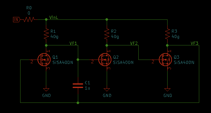
I'm unsure though will it be possible to substitute the star from three 100 pF capacitors with a single one 68pF?
Could you also isolate T4 and T5 from the oscillator, please, so the AM1 won't measure their leakage? It's interesting to compare that cascade to a MOSFET.
-
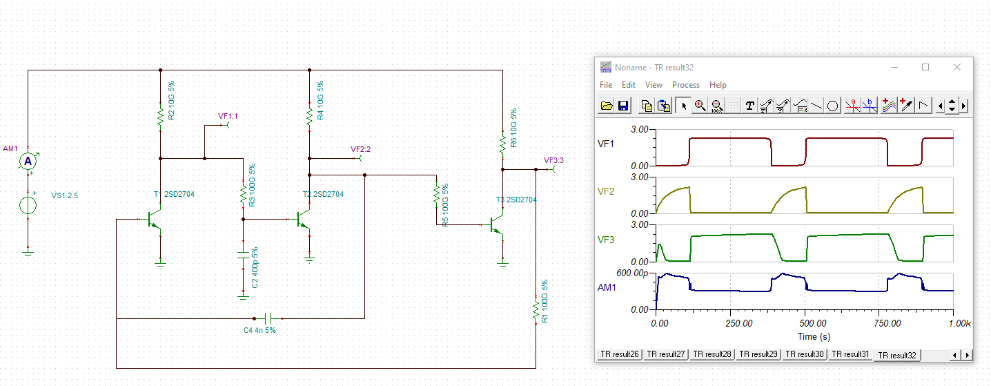
@NeverDie Congratulations! Looks very holistic. The only model needed is 2SD2704 - cool! :the_horns:
I'm unsure though will it be possible to substitute the star from three 100 pF capacitors with a single one 68pF?
Could you also isolate T4 and T5 from the oscillator, please, so the AM1 won't measure their leakage? It's interesting to compare that cascade to a MOSFET.
-
@NeverDie Congratulations! Looks very holistic. The only model needed is 2SD2704 - cool! :the_horns:
I'm unsure though will it be possible to substitute the star from three 100 pF capacitors with a single one 68pF?
Could you also isolate T4 and T5 from the oscillator, please, so the AM1 won't measure their leakage? It's interesting to compare that cascade to a MOSFET.
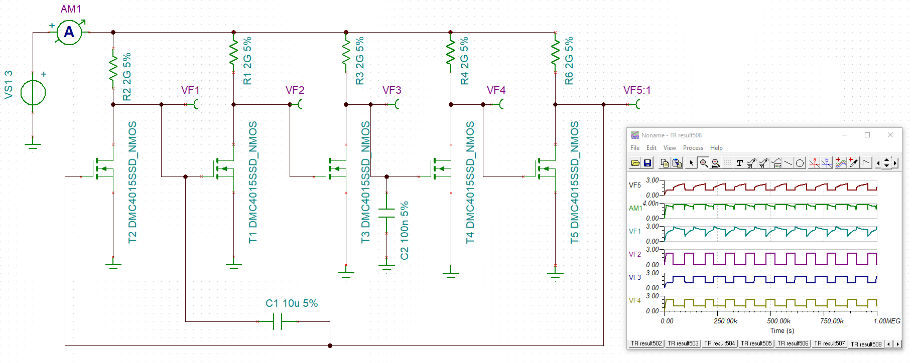
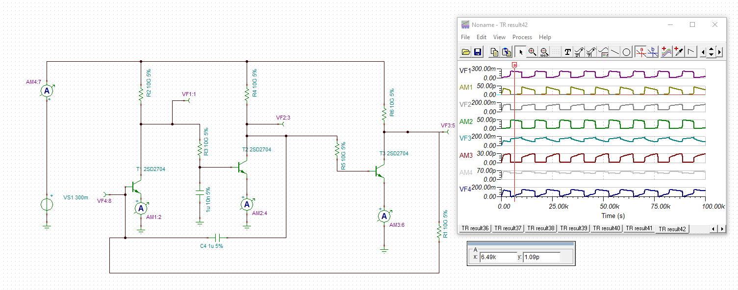
@Mishka said in 💬 The Harvester: ultimate power supply for the Raybeacon DK:
Could you also isolate T4 and T5 from the oscillator, please, so the AM1 won't measure their leakage? It's interesting to compare that cascade to a MOSFET.
Maybe this kind of separation better answers your question about the leakage?
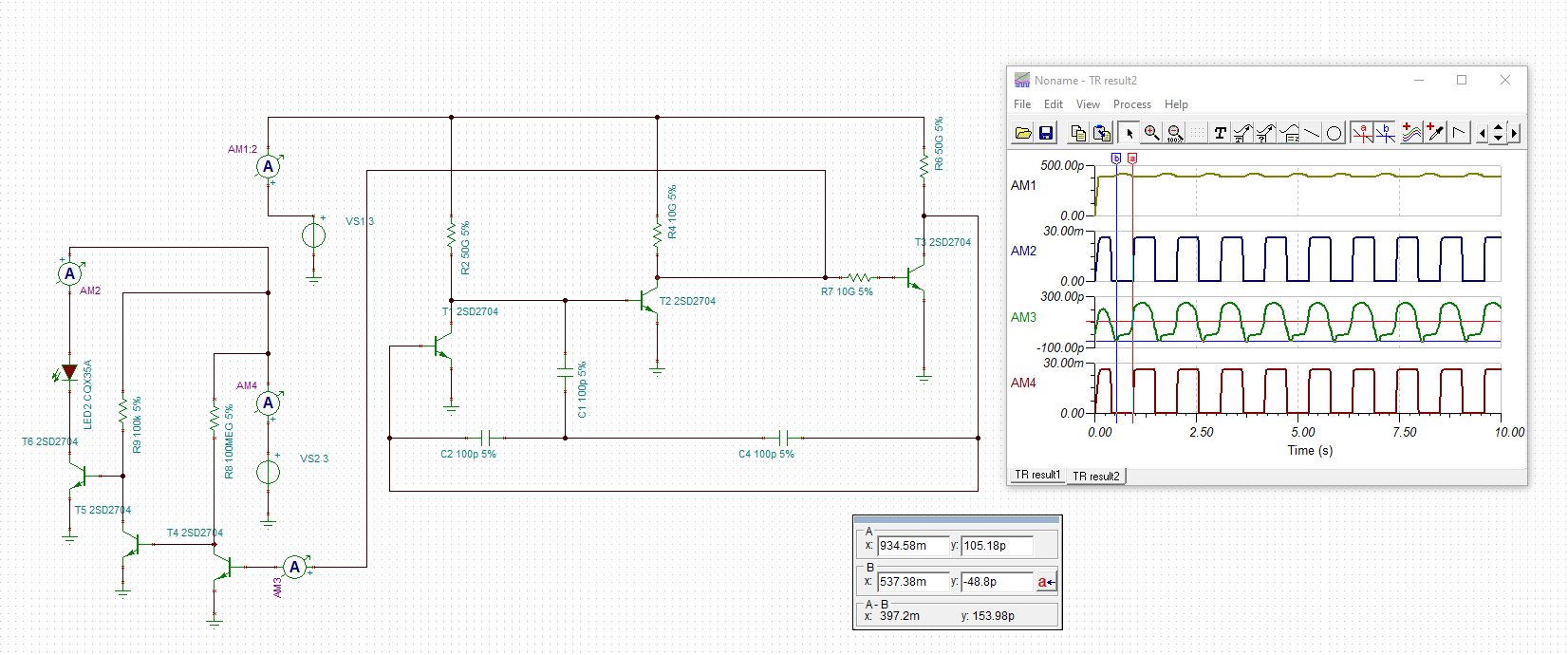
AM3 breaks out the timer leakage into T4 as a separate line item so you can more easily compare it to what the leakage of a mosfet would be.