💬 The Harvester: ultimate power supply for the Raybeacon DK
-
@NeverDie said in 💬 The Harvester: ultimate power supply for the Raybeacon DK:
somewhere around 100 lux or higher is the practical limit for small footprint sensors.
I'm realizing now that this is hogwash because today after getting my lux meter out of mothballs I'm noticing that my solar calculator works just fine down to around 15 lux, which is when its LCD starts to fade out. It suggests that powerfilm probably just isn't one of the better performing solar cells out there.
@NeverDie Wow! Are you sure the lux meter is working properly? 15 lux is about as low as 25 cm from a candle fire which is awfully low.
So, since the ADP5091 is also on the list now, I think it becomes necessary to put all the mentioned power harvesters side by side so we can compare at least basic parameters. Please take a look to the Google Spreadsheet listing some of the tiny harvesters. Please note, The Analog Devices has about ten harvesters which may be described as "tiny", but so far the sheet is covering only ADP509x series. I'm going to add the LTC series later.
From brief analysis, it looks like the Startup Input Voltage and the Startup Input Power are placing the major constraint on PV panel. Of course, the panel should be also able to supply voltage required to cold-boot the harvester. Such, under the low-light conditions (50 lx to 100 lx in a dim room) power capabilities of both of my panels are simply not sufficient to bootstrap the SPV1050: the IXYS is too weak and works starting from 150 lx, and the SCNE is good for boost, but still require 150 lx to reach 2.6V at STORE (the data is for the charts I've posted earlier):
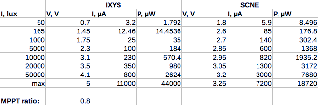
Therefore any panel which can reach required voltage and provide enough power should make the harvesting IC work. Please also note, that after cold-boot almost any harvester can work on a lower power (usually 1.5 - 3 times lower than it was required to start).
Also, in the table there is a class of super-tiny harvesters, namely the Cypress S6AE102(3)A and Ricoh R1800K. They can charge a store by harvesting source with less than 1µW capability. At the same time, the EM8500 looks like the most sophisticated embedded solution with lots of features. The rest of harvesters are quite nice ICs for a modular system.
-
@NeverDie Wow! Are you sure the lux meter is working properly? 15 lux is about as low as 25 cm from a candle fire which is awfully low.
So, since the ADP5091 is also on the list now, I think it becomes necessary to put all the mentioned power harvesters side by side so we can compare at least basic parameters. Please take a look to the Google Spreadsheet listing some of the tiny harvesters. Please note, The Analog Devices has about ten harvesters which may be described as "tiny", but so far the sheet is covering only ADP509x series. I'm going to add the LTC series later.
From brief analysis, it looks like the Startup Input Voltage and the Startup Input Power are placing the major constraint on PV panel. Of course, the panel should be also able to supply voltage required to cold-boot the harvester. Such, under the low-light conditions (50 lx to 100 lx in a dim room) power capabilities of both of my panels are simply not sufficient to bootstrap the SPV1050: the IXYS is too weak and works starting from 150 lx, and the SCNE is good for boost, but still require 150 lx to reach 2.6V at STORE (the data is for the charts I've posted earlier):
Therefore any panel which can reach required voltage and provide enough power should make the harvesting IC work. Please also note, that after cold-boot almost any harvester can work on a lower power (usually 1.5 - 3 times lower than it was required to start).
Also, in the table there is a class of super-tiny harvesters, namely the Cypress S6AE102(3)A and Ricoh R1800K. They can charge a store by harvesting source with less than 1µW capability. At the same time, the EM8500 looks like the most sophisticated embedded solution with lots of features. The rest of harvesters are quite nice ICs for a modular system.
@Mishka said in 💬 The Harvester: ultimate power supply for the Raybeacon DK:
Wow! Are you sure the lux meter is working properly? 15 lux is about as low as 25 cm from a candle fire which is awfully low.
I used a cheap consumer grade lux meter to take the measurement, but it's consistent with what Dave Jones reported for the same solar calculator. He did a youtube video on it, and he showed it worked at around 20lux at a coarse level and probably a bit less.
-
@NeverDie Wow! Are you sure the lux meter is working properly? 15 lux is about as low as 25 cm from a candle fire which is awfully low.
So, since the ADP5091 is also on the list now, I think it becomes necessary to put all the mentioned power harvesters side by side so we can compare at least basic parameters. Please take a look to the Google Spreadsheet listing some of the tiny harvesters. Please note, The Analog Devices has about ten harvesters which may be described as "tiny", but so far the sheet is covering only ADP509x series. I'm going to add the LTC series later.
From brief analysis, it looks like the Startup Input Voltage and the Startup Input Power are placing the major constraint on PV panel. Of course, the panel should be also able to supply voltage required to cold-boot the harvester. Such, under the low-light conditions (50 lx to 100 lx in a dim room) power capabilities of both of my panels are simply not sufficient to bootstrap the SPV1050: the IXYS is too weak and works starting from 150 lx, and the SCNE is good for boost, but still require 150 lx to reach 2.6V at STORE (the data is for the charts I've posted earlier):
Therefore any panel which can reach required voltage and provide enough power should make the harvesting IC work. Please also note, that after cold-boot almost any harvester can work on a lower power (usually 1.5 - 3 times lower than it was required to start).
Also, in the table there is a class of super-tiny harvesters, namely the Cypress S6AE102(3)A and Ricoh R1800K. They can charge a store by harvesting source with less than 1µW capability. At the same time, the EM8500 looks like the most sophisticated embedded solution with lots of features. The rest of harvesters are quite nice ICs for a modular system.
@Mishka This is probably worth adding to the list: https://e-peas.com/products/energy-harvesting/photovoltaic/aem10941/
If we add that, I think we have a pretty complete list for a first pass. The e-peas is pretty expensive though, so we could drop it for that reason.
Since covering the worst case seems to be a relevant concern, I think it's important to identify which one can start-up and begin harvesting at the lowest lux level.
15 lux doesn't seem all that dim to the eye. Setting aside the explanation that our eyes have great dynamic range, I still think we should be able to harvest from less than that. I mean, people are able to harvest from fairly weak radio waves, which have far less power.
-
@Mishka This is probably worth adding to the list: https://e-peas.com/products/energy-harvesting/photovoltaic/aem10941/
If we add that, I think we have a pretty complete list for a first pass. The e-peas is pretty expensive though, so we could drop it for that reason.
Since covering the worst case seems to be a relevant concern, I think it's important to identify which one can start-up and begin harvesting at the lowest lux level.
15 lux doesn't seem all that dim to the eye. Setting aside the explanation that our eyes have great dynamic range, I still think we should be able to harvest from less than that. I mean, people are able to harvest from fairly weak radio waves, which have far less power.
@NeverDie Added, thanks! Quite interesting the IC implements some kind of Cuk converter. On the bad side it seems stocked nowhere, but the e-peas only.
Looking for reasons why the Cypress BLE sensor has chosen a Panasonic cell I found the catalogue which also contains number of interesting charts. Such, the chart on page 3 explains why a calculator cell is more efficient in artificial light than the IXYS thing (BTW the IXYS datasheet has it pretty flat on the range from 400 nm to 1100nm).
This all makes me think that there are basically two combos to choose from:
- an amorphous cell and 3µW harvester
- a monocrystalline cell and 15µW harvester with voltage adjusted to panel assembly
But to be honest I'm quite surprised how well performs the SCNE cell I have extracted from the noname calculator.
-
@NeverDie Added, thanks! Quite interesting the IC implements some kind of Cuk converter. On the bad side it seems stocked nowhere, but the e-peas only.
Looking for reasons why the Cypress BLE sensor has chosen a Panasonic cell I found the catalogue which also contains number of interesting charts. Such, the chart on page 3 explains why a calculator cell is more efficient in artificial light than the IXYS thing (BTW the IXYS datasheet has it pretty flat on the range from 400 nm to 1100nm).
This all makes me think that there are basically two combos to choose from:
- an amorphous cell and 3µW harvester
- a monocrystalline cell and 15µW harvester with voltage adjusted to panel assembly
But to be honest I'm quite surprised how well performs the SCNE cell I have extracted from the noname calculator.
@Mishka said in 💬 The Harvester: ultimate power supply for the Raybeacon DK:
This all makes me think that there are basically two combos to choose from:
Not quite. After closer look I've found the AM-5610 outdoor panel of suitable size - only 25x20mm. The panel is capable to produce up to 18mW.
Other interesting panels are: AM-1606 as used on the Cypress BLE, 15x15mm, AM-1456 which is close to SolarBit by size, 25x10mm, and AM-1312 which is exactly of the same size the SCNE I have.
-
@Mishka said in 💬 The Harvester: ultimate power supply for the Raybeacon DK:
This all makes me think that there are basically two combos to choose from:
Not quite. After closer look I've found the AM-5610 outdoor panel of suitable size - only 25x20mm. The panel is capable to produce up to 18mW.
Other interesting panels are: AM-1606 as used on the Cypress BLE, 15x15mm, AM-1456 which is close to SolarBit by size, 25x10mm, and AM-1312 which is exactly of the same size the SCNE I have.
@Mishka I suppose the SC-3722-9 may be too big for your project, but it's worth mentioning because it performs pretty decently under indoor lighting, and you can extract them for cheap from $1 solar keychains, which are widely available. That's all subjective though. I'm not sure how they compare by the numbers.
-
This diode is a bit expensive and too large for your project, but for experimental purposes it seems like the cat's meow as a blocking diode when collecting currents at tiny voltages: http://www.ti.com/lit/ds/symlink/sm74611.pdf
Just 26mv forward voltage drop at an 8a current, and just 0.3ua reverse leakage current at a voltage of 28v. Obviously, those numbers would be far less for the currents and voltages that we're dealing with. It seems to be very nearly an ideal diode, or at least the closest I've ever seen to that.
-
Summarizing the work on the SPV1050 (irrelevant to other ICs mentioned in this topic) please let me publish revision 0.9 of the Harvester board. It addresses some issues found on the previous boards, and introduces number of important changes.
The most noticeable one is that the board now supports both boost and buck-boost DC-DC configurations of the SPV1050. After reviewing some tiny PV panels it was indetified that the maximum working voltage for a tiny panel is about 3V which means the boost mode is more suitable to do the job. Also, tiny high voltage panels (like some SolarBIT models) have very limited current capabilities and in low light conditions simply can't supply enough power in order to make the harvester chip work. It's also important to note that the cold-boot voltage for boost DC-DC is 0.55V which is only about 20% of maximum 3V voltage a panel can gain - please compare that with 2.6V and 4.4V respectively for some most advanced cells. Finally, if in the boost mode the SPV1050 supports TEG modules.
Therefore the BOM was adjusted to the boost configuration with the following thresholds:
Symbol Parameter Value V_uvp Battery under voltage protection threshold 2.4V V_eoc Battery end of charge voltage 3.1V V_oc Source open circuit maximum voltage 4.7V V_mp Maximum power point voltage 78% * V_oc Please note, in the boost mode the SPV1050 will effectively set V_eoc = V_in for all V_in values greater than 3.1V which may cause damage to the battery or the nRF52 SoC. To prevent the negative impact please carefully consider the source.
If the only source you have is a high voltage solar panel, it's possible to adjust the R1-R3 resistors ladder (please refer to the SPV1050 datasheet) and switch the Harvester board to buck-boost mode as follows:

Hint: If the solar panel is really big (like 2W / 12V or so) and you don't need MPPT, it's possible to close the USB Charge jumper and connect the panel to VBUS and GND solder pads in order to employ the 3.2V USB LDO.
The MPPT fixed voltage ratio is set to 78% with resistors R2=2.2M and R3=8.06M. For a TEG module with MPPT ratio at about 50% just replace both R2 and R3 with 5.2M resistors.
Other notable changes included into this release are:
- Fixed some silk layer errors
- The MIC5205-3.2 LDO got missing input filtering capacitor
- The current limiting resistor between the SPV1050 and the tantalum capacitor has been removed
- Connection to the ground plane in some isolated areas was improved
And last, but not least, I'd like to thank the MySensors forum and in particular @NeverDie for his tremendous contributions. It's pure fun to discuss tiny boards with tiny harvesters working from tiny power sources :call_me_hand:
-
Summarizing the work on the SPV1050 (irrelevant to other ICs mentioned in this topic) please let me publish revision 0.9 of the Harvester board. It addresses some issues found on the previous boards, and introduces number of important changes.
The most noticeable one is that the board now supports both boost and buck-boost DC-DC configurations of the SPV1050. After reviewing some tiny PV panels it was indetified that the maximum working voltage for a tiny panel is about 3V which means the boost mode is more suitable to do the job. Also, tiny high voltage panels (like some SolarBIT models) have very limited current capabilities and in low light conditions simply can't supply enough power in order to make the harvester chip work. It's also important to note that the cold-boot voltage for boost DC-DC is 0.55V which is only about 20% of maximum 3V voltage a panel can gain - please compare that with 2.6V and 4.4V respectively for some most advanced cells. Finally, if in the boost mode the SPV1050 supports TEG modules.
Therefore the BOM was adjusted to the boost configuration with the following thresholds:
Symbol Parameter Value V_uvp Battery under voltage protection threshold 2.4V V_eoc Battery end of charge voltage 3.1V V_oc Source open circuit maximum voltage 4.7V V_mp Maximum power point voltage 78% * V_oc Please note, in the boost mode the SPV1050 will effectively set V_eoc = V_in for all V_in values greater than 3.1V which may cause damage to the battery or the nRF52 SoC. To prevent the negative impact please carefully consider the source.
If the only source you have is a high voltage solar panel, it's possible to adjust the R1-R3 resistors ladder (please refer to the SPV1050 datasheet) and switch the Harvester board to buck-boost mode as follows:
Hint: If the solar panel is really big (like 2W / 12V or so) and you don't need MPPT, it's possible to close the USB Charge jumper and connect the panel to VBUS and GND solder pads in order to employ the 3.2V USB LDO.
The MPPT fixed voltage ratio is set to 78% with resistors R2=2.2M and R3=8.06M. For a TEG module with MPPT ratio at about 50% just replace both R2 and R3 with 5.2M resistors.
Other notable changes included into this release are:
- Fixed some silk layer errors
- The MIC5205-3.2 LDO got missing input filtering capacitor
- The current limiting resistor between the SPV1050 and the tantalum capacitor has been removed
- Connection to the ground plane in some isolated areas was improved
And last, but not least, I'd like to thank the MySensors forum and in particular @NeverDie for his tremendous contributions. It's pure fun to discuss tiny boards with tiny harvesters working from tiny power sources :call_me_hand:
@Mishka Looks like a winner. :+1: Once you put it together I'll be interested to hear what the lowest light levels are that you're able to run it at and which solar panels/cells you end up liking the best.
I think there's a good chance it will outperform the eval kits from enOcean, Cypress Semiconductor, Cymbet, and others that rely on a high cold start voltage. In order for them to win they would need to harvest at a lower power than what your chip can manage but somehow also at the higher voltages and with enough power that their chips require, and I'm not sure whether or not those two conditions can be generated simultaneously by real world solar panels.
-
@Mishka Looks like a winner. :+1: Once you put it together I'll be interested to hear what the lowest light levels are that you're able to run it at and which solar panels/cells you end up liking the best.
I think there's a good chance it will outperform the eval kits from enOcean, Cypress Semiconductor, Cymbet, and others that rely on a high cold start voltage. In order for them to win they would need to harvest at a lower power than what your chip can manage but somehow also at the higher voltages and with enough power that their chips require, and I'm not sure whether or not those two conditions can be generated simultaneously by real world solar panels.
@NeverDie Well, the SPV1050 has a nice set of features I need and offers impressive flexibility in a small package. However, when speaking about efficiency the AEM10941 seem outperforms it in every single bit.
The current design reached some level of stability so I think the AEM10941 is what I should try next.
-
Summarizing the work on the SPV1050 (irrelevant to other ICs mentioned in this topic) please let me publish revision 0.9 of the Harvester board. It addresses some issues found on the previous boards, and introduces number of important changes.
The most noticeable one is that the board now supports both boost and buck-boost DC-DC configurations of the SPV1050. After reviewing some tiny PV panels it was indetified that the maximum working voltage for a tiny panel is about 3V which means the boost mode is more suitable to do the job. Also, tiny high voltage panels (like some SolarBIT models) have very limited current capabilities and in low light conditions simply can't supply enough power in order to make the harvester chip work. It's also important to note that the cold-boot voltage for boost DC-DC is 0.55V which is only about 20% of maximum 3V voltage a panel can gain - please compare that with 2.6V and 4.4V respectively for some most advanced cells. Finally, if in the boost mode the SPV1050 supports TEG modules.
Therefore the BOM was adjusted to the boost configuration with the following thresholds:
Symbol Parameter Value V_uvp Battery under voltage protection threshold 2.4V V_eoc Battery end of charge voltage 3.1V V_oc Source open circuit maximum voltage 4.7V V_mp Maximum power point voltage 78% * V_oc Please note, in the boost mode the SPV1050 will effectively set V_eoc = V_in for all V_in values greater than 3.1V which may cause damage to the battery or the nRF52 SoC. To prevent the negative impact please carefully consider the source.
If the only source you have is a high voltage solar panel, it's possible to adjust the R1-R3 resistors ladder (please refer to the SPV1050 datasheet) and switch the Harvester board to buck-boost mode as follows:
Hint: If the solar panel is really big (like 2W / 12V or so) and you don't need MPPT, it's possible to close the USB Charge jumper and connect the panel to VBUS and GND solder pads in order to employ the 3.2V USB LDO.
The MPPT fixed voltage ratio is set to 78% with resistors R2=2.2M and R3=8.06M. For a TEG module with MPPT ratio at about 50% just replace both R2 and R3 with 5.2M resistors.
Other notable changes included into this release are:
- Fixed some silk layer errors
- The MIC5205-3.2 LDO got missing input filtering capacitor
- The current limiting resistor between the SPV1050 and the tantalum capacitor has been removed
- Connection to the ground plane in some isolated areas was improved
And last, but not least, I'd like to thank the MySensors forum and in particular @NeverDie for his tremendous contributions. It's pure fun to discuss tiny boards with tiny harvesters working from tiny power sources :call_me_hand:
@Mishka said in 💬 The Harvester: ultimate power supply for the Raybeacon DK:
The current limiting resistor between the SPV1050 and the tantalum capacitor has been removed
Why removing the resistor? Why not placing it after the (optional) Tantal to protect a downstreamed Batt or Cap?
-
@Mishka said in 💬 The Harvester: ultimate power supply for the Raybeacon DK:
The current limiting resistor between the SPV1050 and the tantalum capacitor has been removed
Why removing the resistor? Why not placing it after the (optional) Tantal to protect a downstreamed Batt or Cap?
@iiibelst There is one. The R7=549Ω is limiting current between the tantalum capacitor and the extension socket. Its purpose is to keep it under 2mA for ML2032. You can bypass it with relevant solder jumper on the board bottom.
The dropped 50Ω resistor was previously located between SPV1050 and the tantalum capacitor.
-
@NeverDie Well, the SPV1050 has a nice set of features I need and offers impressive flexibility in a small package. However, when speaking about efficiency the AEM10941 seem outperforms it in every single bit.
The current design reached some level of stability so I think the AEM10941 is what I should try next.
@Mishka said in 💬 The Harvester: ultimate power supply for the Raybeacon DK:
The current design reached some level of stability so I think the AEM10941 is what I should try next.
Yes, at a 3 microwatt minimum, that chip may be very tough to beat. It has the same 380mv cold start voltage as the ADP5091, but it requires only half the energy. With these tiny solar panels that extra margin might really make a difference under dim indoor lighting conditions.
I guess it's no accident that the AEM10941 is the newest chip. Perhaps it's the constant improvements in cmos technology that it leverages. In which case.... we can probably look forward to even better chips in the future! For sure solar cells and panels continue to improve their efficiency. The markets are finally big enough to support the required R&D for continual improvement. And the mcu's and radios are constantly improving their efficiency so less power is required. It's great to be in the nexus riding a few waves like this, where we can get the benefit of multiplying the improvements together.
-
@Mishka said in 💬 The Harvester: ultimate power supply for the Raybeacon DK:
The current design reached some level of stability so I think the AEM10941 is what I should try next.
Yes, at a 3 microwatt minimum, that chip may be very tough to beat. It has the same 380mv cold start voltage as the ADP5091, but it requires only half the energy. With these tiny solar panels that extra margin might really make a difference under dim indoor lighting conditions.
I guess it's no accident that the AEM10941 is the newest chip. Perhaps it's the constant improvements in cmos technology that it leverages. In which case.... we can probably look forward to even better chips in the future! For sure solar cells and panels continue to improve their efficiency. The markets are finally big enough to support the required R&D for continual improvement. And the mcu's and radios are constantly improving their efficiency so less power is required. It's great to be in the nexus riding a few waves like this, where we can get the benefit of multiplying the improvements together.
@NeverDie That's all true.
Please also note the AEM10941 can regulate up to 5V of input when ADP5091 upper limit is 3.3V.
Again, when speaking about BLE, a beacon (as a low-power application example) has to advertise at least once every 1000ms to be generally usable. For nRF52840 it approximates to about 50µW of power consumption. By adding up some microwatts of the harvester itself it may be safe to expect a panel should be able to produce 60-70µW of energy in average. In turn, this means that those 3µW or 15µW are rather an edge scenario, and there is must be a timeframe when the system can collect all the required electricity. Such, when running from a daylight it should be expected that in February the harvesting will be efficient for at most 8 hours a day. The system must be able to offer minimum (24h/8h)*70µW = 210µW during the light period of time. For the reference, a couple of my IXYS panels can provide only about 150µW when located in 1m from window on the north side.
From the experiments, to me it currently looks more not about possible minimums, but rather about higher efficiency at nominal values. But I admit the difference between 3µW and 50µW doesn't look big either. The sleeping current of the nRF52 is already less than 3µW, so perhaps some time the source and the load can converge.
-
@NeverDie That's all true.
Please also note the AEM10941 can regulate up to 5V of input when ADP5091 upper limit is 3.3V.
Again, when speaking about BLE, a beacon (as a low-power application example) has to advertise at least once every 1000ms to be generally usable. For nRF52840 it approximates to about 50µW of power consumption. By adding up some microwatts of the harvester itself it may be safe to expect a panel should be able to produce 60-70µW of energy in average. In turn, this means that those 3µW or 15µW are rather an edge scenario, and there is must be a timeframe when the system can collect all the required electricity. Such, when running from a daylight it should be expected that in February the harvesting will be efficient for at most 8 hours a day. The system must be able to offer minimum (24h/8h)*70µW = 210µW during the light period of time. For the reference, a couple of my IXYS panels can provide only about 150µW when located in 1m from window on the north side.
From the experiments, to me it currently looks more not about possible minimums, but rather about higher efficiency at nominal values. But I admit the difference between 3µW and 50µW doesn't look big either. The sleeping current of the nRF52 is already less than 3µW, so perhaps some time the source and the load can converge.
@Mishka said in 💬 The Harvester: ultimate power supply for the Raybeacon DK:
Again, when speaking about BLE, a beacon (as a low-power application example) has to advertise at least once every 1000ms to be generally usable.
I read in a couple different places that the maximum bluetooth advertising interval is 10.24 seconds (i.e. 10x your assumption) so if the rest of your math is right that should provide ample headroom for being bluetooth compliant.
-
@Mishka said in 💬 The Harvester: ultimate power supply for the Raybeacon DK:
Again, when speaking about BLE, a beacon (as a low-power application example) has to advertise at least once every 1000ms to be generally usable.
I read in a couple different places that the maximum bluetooth advertising interval is 10.24 seconds (i.e. 10x your assumption) so if the rest of your math is right that should provide ample headroom for being bluetooth compliant.
@NeverDie Yeah, there are also scenarios when a beacon advertises only when it was charged enough - it may wait for several hours before send a packet. But that's rather uncommon application. A typical beacon usually advertises every 100 ms to 1000 ms - this way it can be located quick enough.
-
Closing the loop: today I finally received the sunpower solar cell, so I was able to take a closer look at it. Basically, the traces on the back are interdigitated. So, it looks as though it could be cut along the horizontal axis (if, say, the connection pads are on the left and right) almost as narrow as whatever you might want to. However, it would be ruined if you were to cut along the vertical axis: one pad would remain fine, but all the traces to the other pad would be severed. Maybe in theory they could be re-attached to a new pad with a lot of careful soldering, but that doesn't seem very practical, as the pitch between traces is quite narrow. On the other hand, if one were to use a custom flex film pcb with connection traces that aligned to the severed traces, it might be possible, but still a nontrivial amount of work.
Looked at from the point of view where large surface area is OK: one of the nice things about these cells is that they are reasonably inexpensive considering their 5"x5" width and height, and yet they are quite thin and still easy to connect. However, I suppose they maybe should be coated with something to protect them. A 2K automotive epoxy spray would probably be ideal, but perhaps even a hard automotive acrylic lacquer would be sufficient, as either should be both non-yellowing and moisture proof. Unfortunately, not much seems to be written about what types of coatings work best. Obviously, the commonly used chinese epoxy solar cell coating would be a poor choice, as that stuff degrades under uv and yellows/browns and clouds up quite rapidly.
@NeverDie Interesting. I think the cell may be carefully cut with laser and then properly remetallized. Perhaps can be done with a typical tin based solder paste with some proper flux (I don't know, originally some kind of silver paste is used). Fixing the cell itself into epoxy should be easy.
The nice thing about the process is that it should be virtually possible to create cells of arbitrary shape. However, in order to get usable voltage it might require to build a panel.
-
@NeverDie Interesting. I think the cell may be carefully cut with laser and then properly remetallized. Perhaps can be done with a typical tin based solder paste with some proper flux (I don't know, originally some kind of silver paste is used). Fixing the cell itself into epoxy should be easy.
The nice thing about the process is that it should be virtually possible to create cells of arbitrary shape. However, in order to get usable voltage it might require to build a panel.
@Mishka On second thought, if you were cutting it to a small size then there wouldn't be many traces remaining to be reconnected, so from that point of view it might actually be practical.
For me it's academic because I don't own a laser cutter, and I have no idea what kind of power would be required to cleanly cut one of these cells even if I were to buy one for that purpose. I'd be interested to know though. Even 20 watt lasers are pretty cheap these days. Hooking a laser up to a CNC, which I do have, to execute the cut would be fairly easy.
-
@Mishka On second thought, if you were cutting it to a small size then there wouldn't be many traces remaining to be reconnected, so from that point of view it might actually be practical.
For me it's academic because I don't own a laser cutter, and I have no idea what kind of power would be required to cleanly cut one of these cells even if I were to buy one for that purpose. I'd be interested to know though. Even 20 watt lasers are pretty cheap these days. Hooking a laser up to a CNC, which I do have, to execute the cut would be fairly easy.
@NeverDie My nearest laser service costs about 3-4 dollars for one running meter, can cut 2 mm steel, so never thought about that. On the other hand, with enough number of passes it virtually should be possible even on a DIY CD-ROM laser engraver, especially if mounted on a CNC which is usually more precise than lasers.
I'm expecting that at least three crystals will be required to gain 1.5-2V. For a circle, it sounds reasonable to cut three or four sectors of equal shape. Maybe a 3D printed pallet can be used with top layer protected by epoxy. But I think for the best result additional metallization will be required anyway.