Repeater and blinking leds [SOLVED]
-
I'm using EasyIoT as controller and have 2 sensors (one in the fridge and one outside) and 1 repeater (for the sensor in the fridge). This all works perfectly well. I'm now trying to achieve that on the repeater a red led blinks if temperature in the fridge drops below 4 °C and a green led blinks if temperature rises above 8 °C. I first made a third test sensor that is simply sending a fixed temperature value to the repeater just to see if the message arrives at the repeater and how it should process there. Node id test node is 3 and node id repeater is 7. This is the code for the test node:
<pre><code>
**#include <MySensor.h>
#include <SPI.h>#define TEMP_CHILD 0
unsigned long SLEEP_TIME = 60000;
MySensor gw;
MyMessage msgTemp(TEMP_CHILD, V_TEMP);
void setup()
{
gw.begin();gw.sendSketchInfo("Test Node", "1.0");
gw.present(TEMP_CHILD, S_TEMP);
}void loop()
{
float temperature = 123.0;
gw.send(msgTemp.setDestination(7).set(temperature,1));
gw.sleep(SLEEP_TIME); **
</code></pre>In the serial monitor and server console I can see that this test node is sending the fixed value of "123" to destination 7 (repeater):
send: 3-3-0-7 s=0,c=1,t=0,pt=7,l=5,st=ok:123.0
And then it stops. I have no idea how to process the incoming message at the repeater side (the blinking leds are not the problem but only the processing of the incoming message). I'm using the default MySensors sketch for the repeater. If someone could point me in the right direction (maybe some example somewhere on this forum. Have looked but cannot find it) I would be very gratefull.
-
On the receiver side, during the radio startup, add the name of a subroutine to handle the incoming messages:
gw.begin( incomingMessage );Then you define the subroutine, something like this:
  void incomingMessage(const MyMessage &message) {

    if (message.type == V_LIGHT ) {

        int state = atoi( message.data );

        digitalWrite( LED_PIN ,  state );

     } ;

   };
At the loop routine, you just need to constantly call gw.process. And you should not use sleep, as no message can be received while Arduino+radio are sleeping...
 void loop()
  {
     gw.process();

    // Your logic here - read sensors, send status etc

  }
Hope it helps!
-
Thanks for taking your time. But still no luck with this. I now have stripped both the receiver and transmitter sketch to an absolute minimum. Just to see if a message goes from the transmiiting node (3) to the receiving node (7). If a message arrives at node 7 a led will be on for 2 seconds. But that is not working. Is there something wrong in this receiving sketch?
Receiving sketch:
<pre><code>
**#include <MySensor.h>
#include <SPI.h>MySensor gw;
#define ledPin 6
void setup()
{gw.begin(incomingMessage, AUTO, true);
Serial.begin(115200);
pinMode(ledPin, OUTPUT);
digitalWrite(ledPin, LOW);gw.sendSketchInfo("TEST", "1.0");
}void loop()
{
gw.process();
}void incomingMessage(const MyMessage &message) {
digitalWrite(ledPin, HIGH);
delay(2000);
digitalWrite(ledPin, LOW);
}**
</code></pre> -
@HarryDutch, I don't see anything wrong with your receiver sketch. Two suggestions:
-
Are you able to use the serial-monitor at the receiver node, and confirm if any message is arriving there?
-
If you move the code from IncomingMessage() to loop(), does the LED turn on/off? ( just for the sake ... )
-
-
Moved code from IncomingMessage() to loop() and the led is on for 2 seconds. So the led is working as it should.
Did changed things a little bit . Node 2 (temperature/humidity sensor in the fridge) is sending temperature/humidity to controller and temperature to node 3 (the node with the leds).
gw.send(msgTemp.set(temperature,1));
gw.send(msgHum.set(humidity, 0));
gw.send(msgTemp.setDestination(3).set(temperature,1));//SEND TEMPERATURE ALSO TO NODE 3This is the output serial monitor node 2:
sensor started, id 2
send: 2-2-3-0 s=255,c=0,t=17,pt=0,l=5,st=ok:1.4.1
send: 2-2-3-0 s=255,c=3,t=6,pt=1,l=1,st=ok:3
send: 2-2-3-0 s=255,c=3,t=11,pt=0,l=15,st=ok:Pressure Sensor
send: 2-2-3-0 s=255,c=3,t=12,pt=0,l=3,st=ok:1.0
send: 2-2-3-0 s=0,c=0,t=7,pt=0,l=5,st=ok:1.4.1
send: 2-2-3-0 s=1,c=0,t=6,pt=0,l=5,st=ok:1.4.1
Temperature = 17.10Humidity = 57.90send: 2-2-3-0 s=1,c=1,t=0,pt=7,l=5,st=fail:17.1
send: 2-2-3-0 s=0,c=1,t=1,pt=7,l=5,st=ok:58
send: 2-2-3-3 s=1,c=1,t=0,pt=7,l=5,st=ok:17.1Looking at the last line it seems to me that sending the temperature value to node 3 is ok.
Node 3 (also a repeater) has now a copy of the Relay Actuator sketch where I have changes relays into leds. There are 3 leds that I can now switch on and off by using the controller. This is working. This is the code for the function IncomingMessage():
**void incomingMessage(const MyMessage &message) {
if (message.type==V_LIGHT) {
digitalWrite(message.sensor-1+LED_1, message.getBool()?LED_ON:LED_OFF);
gw.saveState(message.sensor, message.getBool());
}
// ==== THIS IS NOT WORKING ==========================
if (message.type==V_TEMP) {
digitalWrite(6, HIGH);
delay(2000);
digitalWrite(6, LOW);
}
**And this the output of the serial monitor of node 3:
**repeater started, id 3
send: 3-3-0-0 s=255,c=0,t=18,pt=0,l=5,st=ok:1.4.1
send: 3-3-0-0 s=255,c=3,t=6,pt=1,l=1,st=ok:0
send: 3-3-0-0 s=255,c=3,t=11,pt=0,l=3,st=ok:LED
send: 3-3-0-0 s=255,c=3,t=12,pt=0,l=3,st=ok:1.0
send: 3-3-0-0 s=1,c=0,t=3,pt=0,l=5,st=ok:1.4.1
send: 3-3-0-0 s=2,c=0,t=3,pt=0,l=5,st=ok:1.4.1
send: 3-3-0-0 s=3,c=0,t=3,pt=0,l=5,st=ok:1.4.1
read: 2-2-0 s=255,c=0,t=17,pt=0,l=5:1.4.1
send: 2-3-0-0 s=255,c=0,t=17,pt=0,l=5,st=ok:1.4.1
read: 2-2-0 s=255,c=3,t=6,pt=1,l=1:3
send: 2-3-0-0 s=255,c=3,t=6,pt=1,l=1,st=ok:3
read: 2-2-0 s=255,c=3,t=11,pt=0,l=15:Pressure Sensor
send: 2-3-0-0 s=255,c=3,t=11,pt=0,l=15,st=ok:Pressure Sensor
read: 2-2-0 s=255,c=3,t=12,pt=0,l=3:1.0
send: 2-3-0-0 s=255,c=3,t=12,pt=0,l=3,st=ok:1.0
read: 2-2-0 s=0,c=0,t=7,pt=0,l=5:1.4.1
send: 2-3-0-0 s=0,c=0,t=7,pt=0,l=5,st=fail:1.4.1
read: 2-2-0 s=1,c=1,t=0,pt=7,l=5:19.4
send: 2-3-0-0 s=1,c=1,t=0,pt=7,l=5,st=ok:19.4
read: 2-2-0 s=0,c=1,t=1,pt=7,l=5:51
send: 2-3-0-0 s=0,c=1,t=1,pt=7,l=5,st=fail:51
** -
Well...
-
Try put some delay() between sending each message (or leave just a single message to node 3).
-
The relay sketch also acts like a repeater, maybe it is trying to send the message to 'node 3' to GW instead? Try to disable the repeater function:
gw.begin(incomingMessage, AUTO, false );
-
-
Really appriciate your assistance. All this MySensors stuff is working perfectly well, so not getting this node to node communication right is driving me nuts!
First thing tomorrow I will try your suggestions. Thanks again.
-
I'm interested in the concept of node to node messages but for your use case couldn't you just have the gateway send the message to toggle the LEDs once the message gets there?
So
Node inside fridge -> Relay -> Gateway -> LED Noderather than
Node inside fridge -> LED Node
Node inside fridge -> Relay -> Gatewaywhich is what it seems like you are attempting to do.
Also I had not thought of putting a node in a fridge before but I'll be looking into that now.
-
@Chaotic , I was about to suggest the same to @HarryDutch , however it seems he wants to take the GW out of the equation (for some reason that we don't know).
By putting the GW in the middle it should work perfectly well, I do agree with you.
-
@rvendrame and Chaotic
You're both right of course. I'm now using the automation function in EasyIoT and that's working. So Node inside fridge -> Relay -> Gateway -> LED Node. On the other hand: node to node communication should be possible so I will do some more testing to see if I can get it to work. Thanks for now.
I wasn't saying don't look at the problem. I think Node to Node communication should work.
It just this comic
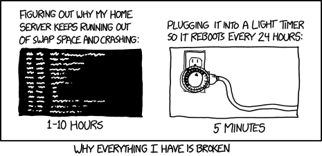
comes to mindAt a certain point you have to realize you are solving the problem out of principle (which is a valid reason) rather than to solve the problem.
-
Hahaha. I've printed your comic. It's hanging now in front of me to remind me that there are different ways to solve a problem. By using the GW I now have a perfectly working project. Thanks for pointing me into the right direction. But I will still try to get the node to node communication working although it's no longer a problem!
@HarryDutch The comic is actually from XKCD if you click the image it should take you to the actual site.
Hello! It looks like you're interested in this conversation, but you don't have an account yet.
Getting fed up of having to scroll through the same posts each visit? When you register for an account, you'll always come back to exactly where you were before, and choose to be notified of new replies (either via email, or push notification). You'll also be able to save bookmarks and upvote posts to show your appreciation to other community members.
With your input, this post could be even better 💗
Register Login