Home Assistent + Serial Gateway + Motion Sensor
-
Hi folks,
I'm sorry for asking, but I'm totally new to mysensors and home assistent, but I've already read a lot and watched youtube videos but in fact I'm right now not aware what I should do next.
First of all, my setup is home assistent running on a raspberry pi 4 Model B. I've installed MySensors Libarary 2.3.2 and used the SerialGateway Sketch with some modifications to add a motion sensor directly on the Gateway to test the functionality.
This is what my code looks like on an arduino nano:
// Enable debug prints to serial monitor
#define MY_DEBUG

// Enable and select radio type attached
#define MY_RADIO_RF24
//#define MY_RADIO_NRF5_ESB
//#define MY_RADIO_RFM69
//#define MY_RADIO_RFM95

// Set LOW transmit power level as default, if you have an amplified NRF-module and
// power your radio separately with a good regulator you can turn up PA level.
#define MY_RF24_PA_LEVEL RF24_PA_LOW

// Enable serial gateway
#define MY_GATEWAY_SERIAL

// Define a lower baud rate for Arduinos running on 8 MHz (Arduino Pro Mini 3.3V & SenseBender)
#if F_CPU == 8000000L
//#define MY_BAUD_RATE 38400
#define MY_BAUD_RATE 115200
#endif

// Enable inclusion mode
#define MY_INCLUSION_MODE_FEATURE
// Enable Inclusion mode button on gateway
//#define MY_INCLUSION_BUTTON_FEATURE

// Inverses behavior of inclusion button (if using external pullup)
//#define MY_INCLUSION_BUTTON_EXTERNAL_PULLUP

// Set inclusion mode duration (in seconds)
#define MY_INCLUSION_MODE_DURATION 60
// Digital pin used for inclusion mode button
//#define MY_INCLUSION_MODE_BUTTON_PIN  3

// Set blinking period
#define MY_DEFAULT_LED_BLINK_PERIOD 300

// Inverses the behavior of leds
//#define MY_WITH_LEDS_BLINKING_INVERSE

// Flash leds on rx/tx/err
// Uncomment to override default HW configurations
//#define MY_DEFAULT_ERR_LED_PIN 4  // Error led pin
//#define MY_DEFAULT_RX_LED_PIN  6  // Receive led pin
//#define MY_DEFAULT_TX_LED_PIN  5  // the PCB, on board LED

#include <MySensors.h>

uint32_t SLEEP_TIME = 120000; // Sleep time between reports (in milliseconds)
#define DIGITAL_INPUT_SENSOR 3   // The digital input you attached your motion sensor.  (Only 2 and 3 generates interrupt!)
#define CHILD_ID 1   // Id of the sensor child

// Initialize motion message
MyMessage msg(CHILD_ID, V_TRIPPED);

void setup()
{
	// Setup locally attached sensors
  pinMode(DIGITAL_INPUT_SENSOR, INPUT);      // sets the motion sensor digital pin as input
}

void presentation()
{
	// Present locally attached sensors
  // Send the sketch version information to the gateway and Controller
  sendSketchInfo("Motion Sensor", "1.0");

  // Register all sensors to gw (they will be created as child devices)
  present(CHILD_ID, S_MOTION);
}

void loop()
{
	// Send locally attached sensor data here
  // Read digital motion value
  bool tripped = digitalRead(DIGITAL_INPUT_SENSOR) == HIGH;

  Serial.println(tripped);
  send(msg.set(tripped?"1":"0"));  // Send tripped value to gw

  // Sleep until interrupt comes in on motion sensor. Send update every two minute.
  sleep(digitalPinToInterrupt(DIGITAL_INPUT_SENSOR), CHANGE, SLEEP_TIME);
}
In the configure.yml File I've added the following lines as described here:
# Example configuration.yaml entry
mysensors:
  gateways:
    - device: '/dev/ttyUSB0'
      baud_rate: 115200
#      baud_rate: 38400
      nodes:
        1:
          name: 'Motion Sensor'
  persistence: true
  version: 2.0
At the moment I get the following message:
Unable to connect to /dev/ttyUSB0But as I connect the gateway it I can see, that /dev/ttyUSB0 should be correct.
Any ideas?
-
I'm not very good with HA but in the GW sketch, to me it seems that you test if the Arduino is running on 8 MHz (#if F_CPU == 8000000L), which I guess it is not. So the #DEFINE MY_BAUD_RATE 115200 is never executed.
So then the GW runs at what baud rate?
Try to move the #DEFINE outside of the #if -- #endif and maybe set a lower baud rate, also in the HA .yml
I have never been so busy since I retired!
-
I'm not very good with HA but in the GW sketch, to me it seems that you test if the Arduino is running on 8 MHz (#if F_CPU == 8000000L), which I guess it is not. So the #DEFINE MY_BAUD_RATE 115200 is never executed.
So then the GW runs at what baud rate?
Try to move the #DEFINE outside of the #if -- #endif and maybe set a lower baud rate, also in the HA .yml
Thank you for that hint. I've actually used the default code and just copied the code of motion sensor at the specific functions including all the defines.
Anyway, I still get the message:
Gateway /dev/ttyUSB0 not ready after 15.0 secs so continuing with setup -
Thank you for that hint. I've actually used the default code and just copied the code of motion sensor at the specific functions including all the defines.
Anyway, I still get the message:
Gateway /dev/ttyUSB0 not ready after 15.0 secs so continuing with setup@ATha1 I have not used Home Assistant myself, but this part of the installation instructions might be relevant:
If you are using an original Arduino as a serial gateway, the port will be named ttyACM*. The exact number can be determined with the command shown below.
ls /dev/ttyACM*
-
@ATha1 I have not used Home Assistant myself, but this part of the installation instructions might be relevant:
If you are using an original Arduino as a serial gateway, the port will be named ttyACM*. The exact number can be determined with the command shown below.
ls /dev/ttyACM*
-
Thank you for your reply.
I’ve seen this but I couldn’t find any device under /dev/ttyACM*
But I found /dev/ttyUSB0@ATha1 ok. Does USB0 disappear when you disconnect the Arduino? If it does, you can be pretty sure you've got the right name.
It could be a permission problem. The instructions at the "Component could not be set up" section at the end of https://www.home-assistant.io/docs/z-wave/installation/ looks like the same stuff that is often needed for usb devices.
-
@ATha1 ok. Does USB0 disappear when you disconnect the Arduino? If it does, you can be pretty sure you've got the right name.
It could be a permission problem. The instructions at the "Component could not be set up" section at the end of https://www.home-assistant.io/docs/z-wave/installation/ looks like the same stuff that is often needed for usb devices.
@mfalkvidd
Yes /dev/ttyUSB0 disappiers as I unplug the Arduino Nano Gateway and comes back when I connect it to USB again. So far so good, USB0 should be fine.When I do
ls -l /dev/ttyUSB0it shows something equal to the link you gave.
So owner 'root', group 'dialout'Most of the shell commands aren't available, for example no sudo, however I'm root, but also no usermod .
Here is what the log-file said:
2020-03-21 19:26:10 ERROR (MainThread) [mysensors] read failed: device reports readiness to read but returned no data (device disconnected or multiple access on port?) 2020-03-21 19:26:10 ERROR (MainThread) [mysensors.gateway_serial] Unable to connect to /dev/ttyUSB0 -
@ATha1 nice work. I'm out of ideas unfortunately. Hopefully someone with HA experience is able to help.
@mfalkvidd
I've enabled debugging:
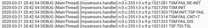 
I've got this also on my Serial Monitor within the Arduino IDE. Is there the problem maybe somewhere else?
-
OK I found the reason.
I had to disable MY_RADIO_RF24 and MY_RF24_PA_LEVEL
so I commented out line 44 and 51 and it worked.Sketch code:
/**
* The MySensors Arduino library handles the wireless radio link and protocol
* between your home built sensors/actuators and HA controller of choice.
* The sensors forms a self healing radio network with optional repeaters. Each
* repeater and gateway builds a routing tables in EEPROM which keeps track of the
* network topology allowing messages to be routed to nodes.
*
* Created by Henrik Ekblad <henrik.ekblad@mysensors.org>
* Copyright (C) 2013-2019 Sensnology AB
* Full contributor list: https://github.com/mysensors/MySensors/graphs/contributors
*
* Documentation: http://www.mysensors.org
* Support Forum: http://forum.mysensors.org
*
* This program is free software; you can redistribute it and/or
* modify it under the terms of the GNU General Public License
* version 2 as published by the Free Software Foundation.
*
*******************************
*
* DESCRIPTION
* The ArduinoGateway prints data received from sensors on the serial link.
* The gateway accepts input on serial which will be sent out on radio network.
*
* The GW code is designed for Arduino Nano 328p / 16MHz
*
* Wire connections (OPTIONAL):
* - Inclusion button should be connected between digital pin 3 and GND
* - RX/TX/ERR leds need to be connected between +5V (anode) and digital pin 6/5/4 with resistor 270-330R in a series
*
* LEDs (OPTIONAL):
* - To use the feature, uncomment any of the MY_DEFAULT_xx_LED_PINs
* - RX (green) - blink fast on radio message received. In inclusion mode will blink fast only on presentation received
* - TX (yellow) - blink fast on radio message transmitted. In inclusion mode will blink slowly
* - ERR (red) - fast blink on error during transmission error or receive crc error
*
*/

// Enable debug prints to serial monitor
#define MY_DEBUG


// Enable and select radio type attached
//#define MY_RADIO_RF24
//#define MY_RADIO_NRF5_ESB
//#define MY_RADIO_RFM69
//#define MY_RADIO_RFM95

// Set LOW transmit power level as default, if you have an amplified NRF-module and
// power your radio separately with a good regulator you can turn up PA level.
//#define MY_RF24_PA_LEVEL RF24_PA_LOW

// Enable serial gateway
#define MY_GATEWAY_SERIAL

// Define a lower baud rate for Arduinos running on 8 MHz (Arduino Pro Mini 3.3V & SenseBender)
//#if F_CPU == 8000000L
#define MY_BAUD_RATE 38400
//#define MY_BAUD_RATE 115200
//#endif

// Enable inclusion mode
#define MY_INCLUSION_MODE_FEATURE
// Enable Inclusion mode button on gateway
//#define MY_INCLUSION_BUTTON_FEATURE

// Inverses behavior of inclusion button (if using external pullup)
//#define MY_INCLUSION_BUTTON_EXTERNAL_PULLUP

// Set inclusion mode duration (in seconds)
#define MY_INCLUSION_MODE_DURATION 60
// Digital pin used for inclusion mode button
//#define MY_INCLUSION_MODE_BUTTON_PIN  3

// Set blinking period
#define MY_DEFAULT_LED_BLINK_PERIOD 300

// Inverses the behavior of leds
//#define MY_WITH_LEDS_BLINKING_INVERSE

// Flash leds on rx/tx/err
// Uncomment to override default HW configurations
//#define MY_DEFAULT_ERR_LED_PIN 4  // Error led pin
//#define MY_DEFAULT_RX_LED_PIN  6  // Receive led pin
//#define MY_DEFAULT_TX_LED_PIN  5  // the PCB, on board LED

#include <MySensors.h>

uint32_t SLEEP_TIME = 120000; // Sleep time between reports (in milliseconds)
#define DIGITAL_INPUT_SENSOR 3   // The digital input you attached your motion sensor.  (Only 2 and 3 generates interrupt!)
#define CHILD_ID 1   // Id of the sensor child

// Initialize motion message
MyMessage msg(CHILD_ID, V_TRIPPED);

void setup()
{
	// Setup locally attached sensors
  pinMode(DIGITAL_INPUT_SENSOR, INPUT);      // sets the motion sensor digital pin as input
}

void presentation()
{
	// Present locally attached sensors
  // Send the sketch version information to the gateway and Controller
  sendSketchInfo("Motion Sensor", "1.0");

  // Register all sensors to gw (they will be created as child devices)
  present(CHILD_ID, S_MOTION);
}

void loop()
{
	// Send locally attached sensor data here
  // Read digital motion value
  bool tripped = digitalRead(DIGITAL_INPUT_SENSOR) == HIGH;

  Serial.println(tripped);
  send(msg.set(tripped?"1":"0"));  // Send tripped value to gw

  // Sleep until interrupt comes in on motion sensor. Send update every two minute.
  sleep(digitalPinToInterrupt(DIGITAL_INPUT_SENSOR), CHANGE, SLEEP_TIME);
}
I've also changed some lines in my configuration.yml
mysensors:
  gateways:
    - device: '/dev/ttyUSB0'
      persistence_file: 'mysensors/mysensors.json'
      baud_rate: 38400
  persistence: true
  version: '2.3.2'
And the motion sensor showed up as Motion Sensor
Hello! It looks like you're interested in this conversation, but you don't have an account yet.
Getting fed up of having to scroll through the same posts each visit? When you register for an account, you'll always come back to exactly where you were before, and choose to be notified of new replies (either via email, or push notification). You'll also be able to save bookmarks and upvote posts to show your appreciation to other community members.
With your input, this post could be even better 💗
Register Login