
Ceech Board MOSFET Pin DIGITALWRITE Problem
-
Hi, I'm working with Ceech-Board for a pool sensor. I'm rewriting the code from V1.5 to 2.x. I encountered a problem with DIGITALWRITE which I can't explain.
Only if I set PINMODE unequal to the PIN for DIGITALWRITE, this output works.
void setup() {
  pinMode(5, OUTPUT); // Setzt den Digitalpin 13 als Outputpin
}

void loop() {
  digitalWrite(4, HIGH); // Setzt den Digitalpin 13 auf HIGH = "Ein"
  delay(1000);            // Wartet eine Sekunde
  digitalWrite(4, LOW);  // Setzt den Digitalpin 13 auf LOW = "Aus"
  delay(1000);            // Wartet eine Sekunde
}
It worked with pin 3, 5 and 13 e.g.
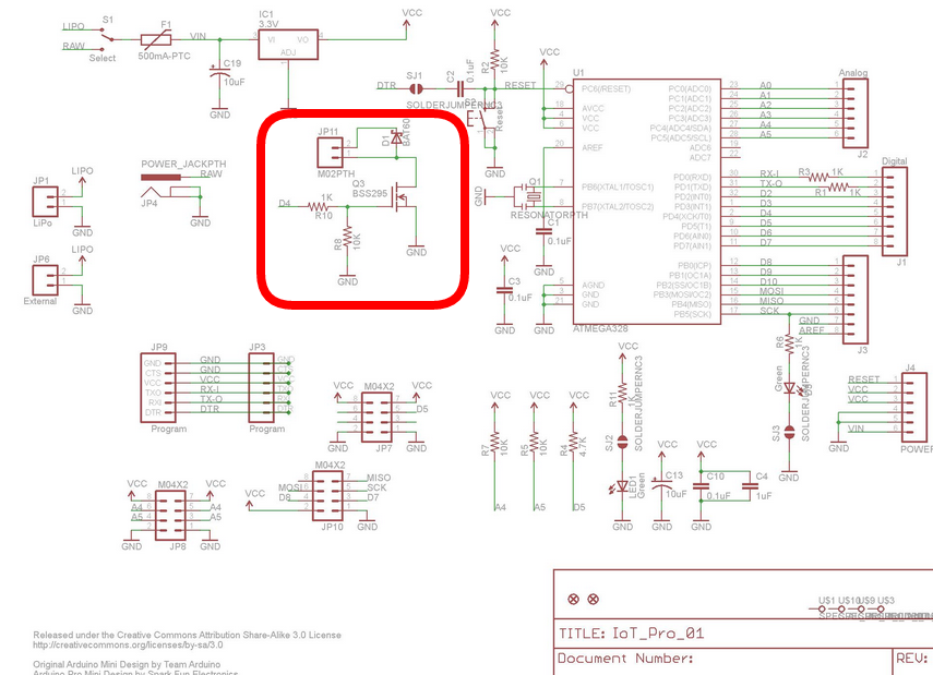
On the board the PIN D4 is followed by a MOSFET for switching. This worked once, once again not. No I seem to have found the problem, but what is the cause?
-
Hi, I'm working with Ceech-Board for a pool sensor. I'm rewriting the code from V1.5 to 2.x. I encountered a problem with DIGITALWRITE which I can't explain.
Only if I set PINMODE unequal to the PIN for DIGITALWRITE, this output works.
void setup() {
  pinMode(5, OUTPUT); // Setzt den Digitalpin 13 als Outputpin
}

void loop() {
  digitalWrite(4, HIGH); // Setzt den Digitalpin 13 auf HIGH = "Ein"
  delay(1000);            // Wartet eine Sekunde
  digitalWrite(4, LOW);  // Setzt den Digitalpin 13 auf LOW = "Aus"
  delay(1000);            // Wartet eine Sekunde
}
It worked with pin 3, 5 and 13 e.g.
On the board the PIN D4 is followed by a MOSFET for switching. This worked once, once again not. No I seem to have found the problem, but what is the cause?
@paqor I recently converted the sketch to 2.x . Here it goes:
/** * The MySensors Arduino library handles the wireless radio link and protocol * between your home built sensors/actuators and HA controller of choice. * The sensors forms a self healing radio network with optional repeaters. Each * repeater and gateway builds a routing tables in EEPROM which keeps track of the * network topology allowing messages to be routed to nodes. * * Created by Henrik Ekblad <henrik.ekblad@mysensors.org> * Copyright (C) 2013-2015 Sensnology AB * Full contributor list: https://github.com/mysensors/Arduino/graphs/contributors * * Documentation: http://www.mysensors.org * Support Forum: http://forum.mysensors.org * * This program is free software; you can redistribute it and/or * modify it under the terms of the GNU General Public License * version 2 as published by the Free Software Foundation. * ******************************* * * REVISION HISTORY * Version 1.0 - Initial Version by rvendrame * ****************************** * DESCRIPTION * Floating Swiming pool sensor based on ceech's arista board * (see https://www.tindie.com/products/ceech/astri-arista/ ) * Solar-powered (+Li-ion 18650 battery backup) * PH Measurement via A3 pin, using DFrobot SEN0161 PH sensor * (see https://www.dfrobot.com/wiki/index.php/PH_meter(SKU:_SEN0161) * ORP Measurement via A1 pin, using Phidgets 1130_0 board + 3556_0 Electrode * (see http://www.phidgets.com/products.php?product_id=1130) * (see http://www.phidgets.com/products.php?product_id=3556) * Temp sensor via D4 pin, using DS18B20 sensor * (see https://create.arduino.cc/projecthub/TheGadgetBoy/ds18b20-digital-temperature-sensor-and-arduino-9cc806 ) * * Revisions: * 1.0 ( ??? 2017 ) - Initial version * 1.1 ( Jan 2020 ) - MySensors 2.x port */ // Enable debug prints to serial monitor //#define MY_DEBUG // CEECH BOARD #define CEECH // Define a static node address, AUTO or 1-255 fixed #define MY_NODE_ID AUTO #define MY_PARENT_NODE_ID AUTO // Enable and select radio type attached #define MY_RADIO_RF24 // MY_RADIO_RFM69 // MySensors #define SN "myPoolWater" #define SV "1.2" #ifdef CEECH #define MY_RF24_CE_PIN 7 // Ceech Arista board #define MY_RF24_CS_PIN 8 // Ceech Arista board #endif // Includes ------------------------------------------- #include <MySensors.h> #include <SPI.h> #include <OneWire.h> #include <DallasTemperature.h> // External IO Pins #define PH_PIN A3 // pH Sensor dfrobot SKU SEN0161 #define ORP_PIN A1 // ORP Sensor phidgets ASR2801 (3556_0) + 1103_0 #define ONE_WIRE_BUS 5 // One wire bus // Runtime constants #define day 86400000L // 86400000 milliseconds in a day #define hour 3600000L // 3600000 milliseconds in an hour #define minute 60000L // 60000 milliseconds in a minute #define second 1000L // 1000 milliseconds in a second // Ceech-Arista Internal connections #define current A6 // Charging current from Solar Panel #define cell A2 // Voltage at Solar Panel #define lipo A0 // Voltage at Battery #define CHRG A7 // Charge indicator ( 0 means 'charging' ) #define POWER 4 // MOSFET driver on 5V Step up (to power the sensors) #define R1 47000.0 // resistance of R1 #define R2 10000.0 // resistance of R2 // mySensors objects MyMessage ph_msg( 2, V_PH ), orp_msg( 3, V_ORP ), temp_msg( 1, V_TEMP ), bat_msg( 199 , V_VOLTAGE ), var1_msg( 0 , V_VAR1 ), var2_msg( 0 , V_VAR2 ), var3_msg( 0 , V_VAR3 ); // Setup a oneWire instance to communicate with any OneWire devices // (not just Maxim/Dallas temperature ICs) OneWire oneWire(ONE_WIRE_BUS); // Pass our oneWire reference to Dallas Temperature. DallasTemperature dallas(&oneWire); // Misc #define pHOffset 0.00 // pH deviation compensate #define samplingInterval 20 // in miliseconds #define arrayLenth 40 // times of collection // PH / ORP / Temp Reading static unsigned long samplingTime = millis(); static float temp, ph, orp, voltage; static float aux, dif, old_ph=999, old_orp=999, old_temp=999; int battery, counter = -1, old_bat=999, old_volt=9999; int readings[arrayLenth]; //Store the average value of the sensor feedback int arrayIndex = 0; // Misc float vout = 0.0; float vin = 0.0; int value = 0; //// SETUP void setup() { Serial.begin( MY_BAUD_RATE ); Serial.println(F("Init...")); // IO PINS pinMode( POWER , OUTPUT ); pinMode( PH_PIN , INPUT ); pinMode( ORP_PIN , INPUT ); } //// PRESENTATION void presentation() { sendSketchInfo(SN, SV); present( 1, S_TEMP ); // Temperature present( 2, S_WATER_QUALITY ); // PH present( 3, S_WATER_QUALITY ); // ORP } //// LOOP void loop() { // Force a refresh on each hour... if ( ++counter == 5 ) { old_ph = old_orp = old_temp = -999; old_bat = old_volt = -999; counter = 0; } // Internal board/battery status digitalWrite( POWER , true ); Serial.println("5V Power ON - Wait 5s"); wait(5000); float napetost = readVcc(); Serial.println("*Internal:"); value = analogRead(cell); vout = (value * napetost) / 1024.0; vin = vout / (R2 / (R1 + R2)); if (vin < 0.09) vin = 0.0; float tok = ((analogRead(current) * napetost / 1024 ) * 250) / 3.3; // convert the ADC value to miliamps float baterija = ( analogRead(lipo) * napetost / 1024 ) * 2; // measuring battery voltage int polnjenje = analogRead(CHRG); Serial.print("Vcc = "); Serial.print(napetost); Serial.println("V"); //delay(400); Serial.print("Charge current = "); Serial.print(tok); Serial.println("mA"); //delay(400); Serial.print("Solar cell voltage = "); Serial.print(vin); Serial.println("V"); //delay(400); Serial.print("Battery voltage = "); Serial.print(baterija); Serial.print("V "); aux = constrain( map( baterija*1000 , 2200 , 4000 , 0 , 100 ) , 0 , 100 ); Serial.print( aux , 0 ); Serial.println("%"); dif = aux - old_bat; if ( abs( dif ) > 0 ) { old_bat = aux; send( bat_msg.set(baterija,2) ); sendBatteryLevel( aux) ; send ( var3_msg.set(vin,2) ); } //delay(400); Serial.print("CHRG = "); Serial.println(polnjenje); Serial.println("*External:"); //////// Temp Reading dallas.begin(); // Start up the library dallas.requestTemperatures(); temp = dallas.getTempCByIndex(0); Serial.print( "Temperature: "); Serial.println( temp , 2 ); dif = old_temp - temp; if ( abs( dif ) > 0.01 ) { old_temp = temp; send( temp_msg.set( temp , 2 ) ) ; } //////// PH Reading arrayIndex = 0; while ( arrayIndex < arrayLenth ) if (millis() - samplingTime > samplingInterval) { readings[arrayIndex++] = analogRead(PH_PIN); samplingTime = millis(); } voltage = avergearray( readings, arrayLenth ) * 3.30 / 1024.0; ph = 3.5 * ( voltage + pHOffset ); Serial.print("PH Probe voltage:"); Serial.print(voltage, 4); Serial.print(" pH value: "); Serial.println( ph , 2); dif = old_ph - ph; if ( abs( dif ) > 0.005 ) { old_ph = ph; send( ph_msg.set( ph , 2 ) ) ; send( var1_msg.set( voltage, 4) ); } /////////// ORP arrayIndex = 0; while ( arrayIndex < arrayLenth ) if (millis() - samplingTime > samplingInterval) { readings[arrayIndex++] = analogRead(ORP_PIN); samplingTime = millis(); } voltage = avergearray( readings, arrayLenth ) * 3.31 / 1024.0; orp = ( 2.5 - voltage ) / 1.037 ; Serial.print("ORP Probe voltage:"); Serial.print( voltage, 4); Serial.print(" ORP value: "); Serial.println( orp, 2 ); dif = old_orp - orp; if ( abs( dif ) > 0.005 ) { old_orp = orp; send( orp_msg.set( orp , 2 ) ) ; send( var2_msg.set( voltage, 4) ); } /////////// Sleep digitalWrite( POWER , false ); Serial.println("5V Power OFF"); Serial.print("Runtime: "); time(); Serial.println("Pausing..."); Serial.println("----------------------------"); //delay(715000); wait(500); sleep( 715000U ); // Sleeps for 12m } double avergearray(int* arr, int number) { int i; int max, min; double avg; long amount = 0; if (number <= 0) { Serial.println("Error number for the array to avraging!/n"); return 0; } if (number < 5) { //less than 5, calculated directly statistics for (i = 0; i < number; i++) { amount += arr[i]; } avg = amount / number; return avg; } else { if (arr[0] < arr[1]) { min = arr[0]; max = arr[1]; } else { min = arr[1]; max = arr[0]; } for (i = 2; i < number; i++) { if (arr[i] < min) { amount += min; //arr<min min = arr[i]; } else { if (arr[i] > max) { amount += max; //arr>max max = arr[i]; } else { amount += arr[i]; //min<=arr<=max } }//if }//for avg = (double)amount / (number - 2); }//if return avg; } void time() { long timeNow = millis(); int days = timeNow / day ; //number of days int hours = (timeNow % day) / hour; //the remainder from days division (in milliseconds) divided by hours, this gives the full hours int minutes = ((timeNow % day) % hour) / minute ; //and so on... int seconds = (((timeNow % day) % hour) % minute) / second; // digital clock display of current time Serial.print(days, DEC); printDigits(hours); printDigits(minutes); printDigits(seconds); Serial.println(); } void printDigits(byte digits) { // utility function for digital clock display: prints colon and leading 0 Serial.print(":"); if (digits < 10) Serial.print('0'); Serial.print(digits, DEC); } /* Read internal Vcc reference * */ float readVcc() { signed long resultVcc; float resultVccFloat; // Read 1.1V reference against AVcc ADMUX = _BV(REFS0) | _BV(MUX3) | _BV(MUX2) | _BV(MUX1); delay(10); // Wait for Vref to settle ADCSRA |= _BV(ADSC); // Convert while (bit_is_set(ADCSRA, ADSC)); resultVcc = ADCL; resultVcc |= ADCH << 8; resultVcc = 1126400L / resultVcc; // Back-calculate AVcc in mV resultVccFloat = (float) resultVcc / 1000.0; // Convert to Float return resultVccFloat; } -
Oh, thank you so much. I had to make some small changes though. Maybe it's the newer Ceech Board version.
// IO PINS pinMode( 13 , OUTPUT ); //unclear why this is so ... present(0, S_MULTIMETER); present(0, S_CUSTOM); ... digitalWrite( POWER , HIGH ); ... digitalWrite( POWER , LOW ); -
Hi, I'm working with Ceech-Board for a pool sensor. I'm rewriting the code from V1.5 to 2.x. I encountered a problem with DIGITALWRITE which I can't explain.
Only if I set PINMODE unequal to the PIN for DIGITALWRITE, this output works.
void setup() {
  pinMode(5, OUTPUT); // Setzt den Digitalpin 13 als Outputpin
}

void loop() {
  digitalWrite(4, HIGH); // Setzt den Digitalpin 13 auf HIGH = "Ein"
  delay(1000);            // Wartet eine Sekunde
  digitalWrite(4, LOW);  // Setzt den Digitalpin 13 auf LOW = "Aus"
  delay(1000);            // Wartet eine Sekunde
}
It worked with pin 3, 5 and 13 e.g.
On the board the PIN D4 is followed by a MOSFET for switching. This worked once, once again not. No I seem to have found the problem, but what is the cause?
@paqor said in Ceech Board MOSFET Pin DIGITALWRITE Problem:
You have to set pinMode for the same pin as you want to use as a output.. That is, if you use
pinMode(5, OUTPUT);you also need to usedigitalWrite(5, HIGH);See documentation hereIf you do not set pinMode for a particular pin, then that pin will be set as input by default. And then digitalWrite() will enable / disable the internal pullup on that particular pin.
I also suggest that you use a #define to make sensible names for your pins, that will make your code more readable:
#define RELAY_PIN 5

void setup() {
  pinMode(RELAY_PIN, OUTPUT); // Setzt den Digitalpin 13 als Outputpin
}

void loop() {
  digitalWrite(RELAY_PIN, HIGH); // Setzt den Digitalpin 13 auf HIGH = "Ein"
  delay(1000);            // Wartet eine Sekunde
  digitalWrite(RELAY_PIN, LOW);  // Setzt den Digitalpin 13 auf LOW = "Aus"
  delay(1000);            // Wartet eine Sekunde
}
Hello! It looks like you're interested in this conversation, but you don't have an account yet.
Getting fed up of having to scroll through the same posts each visit? When you register for an account, you'll always come back to exactly where you were before, and choose to be notified of new replies (either via email, or push notification). You'll also be able to save bookmarks and upvote posts to show your appreciation to other community members.
With your input, this post could be even better 💗
Register Login