RFM69 Range issues
-
@skywatch Yes, it should be better for his price of 219 euros ;-)
I bought now the rtlsdr for 29 euros directly from the RTLSDR site from their Chinese store.
My purpose was to see if there was much noise or not in my environment. -
@mfalkvidd It all depends on range and signal to noise ratio. The longer the range the better the receiver SNR nedds to be for the same signal to be received - This thread is about 'Range Issues' so therefore it matters.
You might run into problems if your SDR is less sensitive than your chosen tx/rx pair.
-
@evb From itead it is 139.84 euros. see here https://www.itead.cc/airspy.html
If you can wait until December they usually have a sale on with about 30% discount. That is how I got them for less than £90 GBP....
@skywatch Based on your answers, I see that you seemingly have knowledge in this matter.
I have range issues and just wanted to see if this is due to external environmental factors (neighbors using the same frequency, etc)
And to spend more than 200 euros for something that I will use maybe one time, that was way too much.
(Purchase price manufacturer 140 euros + 10 euros shipping + import taxes because more than 22 euros + customs clearance = 219 euros). I live in Europe where they specialize in taxes :-(I know you usually get what you paid for, so I don't expect extraordinary performance either...
-
Did receive yesterday my RTL-SDR.COM USB stick :-)
A first measure of the spectrum around the 868MHz band from my fix desktop computer with the Airspy SDR# software recommended on the RTL-SDR.COM website.
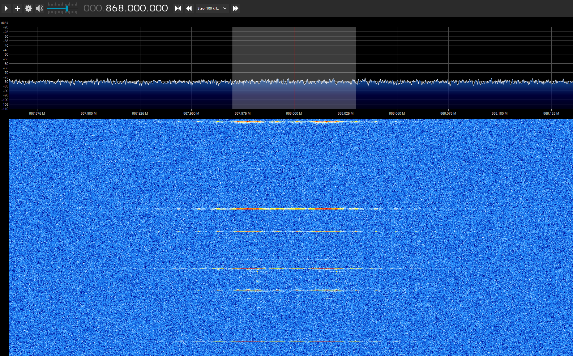
You see clearly the lines in the waterfall blue section when a node sends something.
With my limited knowledge about radio signals and use of this Airspy SDR# Studio software, I think that the spectrum around my house is relatively quiet?Yet another printscreen with the SDR Console version software
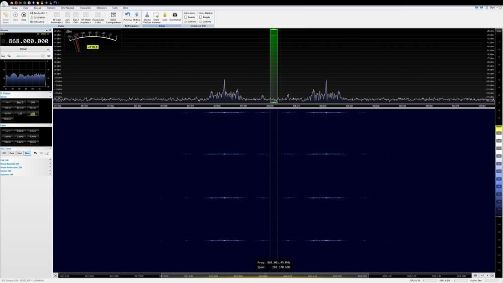
Will install the software now on my laptop to be able to go near the nodes and gateway.
To be continued.Already a question, my RFM69HW are working in the 868Mhz band, yet I see movement at 867.970 MHz and 868.020 MHz. At the center 868 MHz, I see no movement.
Someone with more knowledge about this, can explain this? I would expect a signal at 868 MHz...@evb Yes, i agree your 868MHz doesn't look that busy and shouldn't be the root cause. Have you been able to establish the specific sensor that you have range issues with (i.e. how it look in the spectrum analyzer)? This is a bit easier when working with "dumb" sensors that sends repeatedly every minute or so. Might be a good idea to add a frequent send (just temporarily while troubleshooting this).
-
@skywatch Based on your answers, I see that you seemingly have knowledge in this matter.
I have range issues and just wanted to see if this is due to external environmental factors (neighbors using the same frequency, etc)
And to spend more than 200 euros for something that I will use maybe one time, that was way too much.
(Purchase price manufacturer 140 euros + 10 euros shipping + import taxes because more than 22 euros + customs clearance = 219 euros). I live in Europe where they specialize in taxes :-(I know you usually get what you paid for, so I don't expect extraordinary performance either...
@evb said in RFM69 Range issues:
@skywatch Based on your answers, I see that you seemingly have knowledge in this matter.
Yup! - 40+ years as a licenced radio amateur along with years working on aircraft radar receivers, air-to-air missile seeker heads, underwater systems and satcomms. We had some great equipment at work!
My point is that if the sdr has a noise floor of say -70dBm and the RFM has a noise floor of -80dBm then the RFM can still 'see' interfereing signals that the sdr doesn't, You can see the signal to noise ration in sdr# by looking at the blue bar to the right of the main spectrum display. To get your sdr set to the optimum level you need to adjust the gain to maximise this figure, then you are operating in the optimal domain for SNR and hence what you can see'hear.
When you say 'range issues' what sort of range are we talking about and in what conditions? Have you tried small movements of the radio module as often that can make a difference.
-
@evb said in RFM69 Range issues:
@skywatch Based on your answers, I see that you seemingly have knowledge in this matter.
Yup! - 40+ years as a licenced radio amateur along with years working on aircraft radar receivers, air-to-air missile seeker heads, underwater systems and satcomms. We had some great equipment at work!
My point is that if the sdr has a noise floor of say -70dBm and the RFM has a noise floor of -80dBm then the RFM can still 'see' interfereing signals that the sdr doesn't, You can see the signal to noise ration in sdr# by looking at the blue bar to the right of the main spectrum display. To get your sdr set to the optimum level you need to adjust the gain to maximise this figure, then you are operating in the optimal domain for SNR and hence what you can see'hear.
When you say 'range issues' what sort of range are we talking about and in what conditions? Have you tried small movements of the radio module as often that can make a difference.
@skywatch said in RFM69 Range issues:
My point is that if the sdr has a noise floor of say -70dBm and the RFM has a noise floor of -80dBm then the RFM can still 'see' interfereing signals that the sdr doesn't, You can see the signal to noise ration in sdr# by looking at the blue bar to the right of the main spectrum display. To get your sdr set to the optimum level you need to adjust the gain to maximise this figure, then you are operating in the optimal domain for SNR and hence what you can see'hear.
Like said my knowledge is limited in this matter.
Can you give more information about how to do it? Or point me to some How To's?
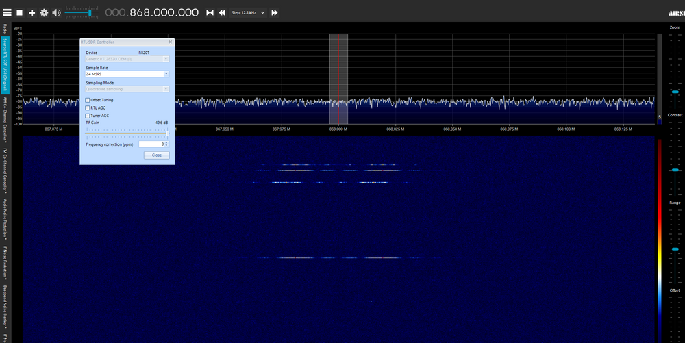
I use the software SDR Console version software and I think you mean this:
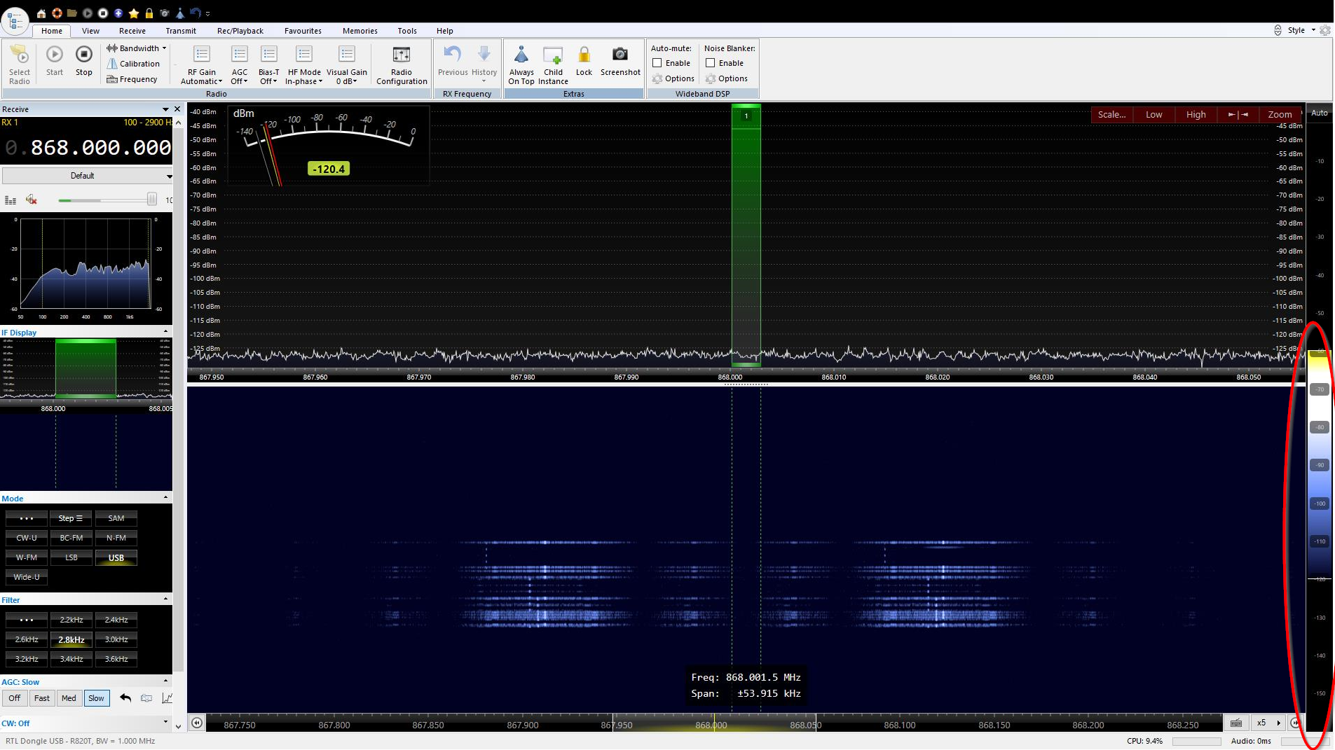
But how to adapt the gain? I played with this, you can move the little white line in this vertical bar up and down, but not knowing what I'm doing is not getting me further :-(
I think that from the picture I can conclude that my environment spectrum is quite, today at least.
My problem is that some messages from this node are not making it to the gateway.
Sometimes it works great for days and then suddenly the node does not send anything.
For this I added already a repeater node between, thinking it would get better, but nada.My idea is now to measure with the SDR at these moments:
- Is the node trying to send a message or not? If I see nothing, then it is a hardware/battery problem of the node itself. If I see the same signal figure, then it is not my node who has a problem
- Is my environment suddenly filled with other signals? blocking my signal?
-
@skywatch said in RFM69 Range issues:
My point is that if the sdr has a noise floor of say -70dBm and the RFM has a noise floor of -80dBm then the RFM can still 'see' interfereing signals that the sdr doesn't, You can see the signal to noise ration in sdr# by looking at the blue bar to the right of the main spectrum display. To get your sdr set to the optimum level you need to adjust the gain to maximise this figure, then you are operating in the optimal domain for SNR and hence what you can see'hear.
Like said my knowledge is limited in this matter.
Can you give more information about how to do it? Or point me to some How To's?
I use the software SDR Console version software and I think you mean this:
But how to adapt the gain? I played with this, you can move the little white line in this vertical bar up and down, but not knowing what I'm doing is not getting me further :-(
I think that from the picture I can conclude that my environment spectrum is quite, today at least.
My problem is that some messages from this node are not making it to the gateway.
Sometimes it works great for days and then suddenly the node does not send anything.
For this I added already a repeater node between, thinking it would get better, but nada.My idea is now to measure with the SDR at these moments:
- Is the node trying to send a message or not? If I see nothing, then it is a hardware/battery problem of the node itself. If I see the same signal figure, then it is not my node who has a problem
- Is my environment suddenly filled with other signals? blocking my signal?
@evbI have not used SDR console yet, I was talking about SDR# (a.k.a. SDR sharp) - It is free to download from the airspy web site and will work with your rtlsdr. I can help you with that if you like.
I had similar problems with nodes suddenly not sending. I don't think it is RF signals that are the problem based on my experience. If a repeater didn't help then in my mind that just confirms it.
I suggest to take a step back and look at things again. Power supply, cabling, solder joints, dupont connectors (only useful for testing really).
Really look at solder joints with a good magnifing glass. If in doubt re-solder. Try and solder as many connections as you can. Dupont connectors have a habit of moving due to thermal expansion and contraction as well as through environmental vibrations (think busy road nearby). If you have to use them then take a pair of pliers and squish the connectors so that they really grip! ;) (remembering of course to take the plastic shield off first!)
Can you post a photo of the node that is causing trouble? And again, what distance are you expecting and in what environment? 10M in an apartment block or 100M in a rural setting?
-
@evbI have not used SDR console yet, I was talking about SDR# (a.k.a. SDR sharp) - It is free to download from the airspy web site and will work with your rtlsdr. I can help you with that if you like.
I had similar problems with nodes suddenly not sending. I don't think it is RF signals that are the problem based on my experience. If a repeater didn't help then in my mind that just confirms it.
I suggest to take a step back and look at things again. Power supply, cabling, solder joints, dupont connectors (only useful for testing really).
Really look at solder joints with a good magnifing glass. If in doubt re-solder. Try and solder as many connections as you can. Dupont connectors have a habit of moving due to thermal expansion and contraction as well as through environmental vibrations (think busy road nearby). If you have to use them then take a pair of pliers and squish the connectors so that they really grip! ;) (remembering of course to take the plastic shield off first!)
Can you post a photo of the node that is causing trouble? And again, what distance are you expecting and in what environment? 10M in an apartment block or 100M in a rural setting?
@skywatch Thanks for wanting to help me.
I have also the SDR# software installed, but was getting quicker a visual result with the other software, that's why I used this software.
So I'm curious how to set my sdr to the optimum level by adjusting the gain.
For photo's you can see them here : https://forum.mysensors.org/topic/11499/checking-mechanical-locked-doors-by-a-battery-based-windows-door-sensor-node
At the end, you have photos of the problem node.Like said, today, the node was working.
I've reprogrammed also the repeater node, because I was doing a new temperature repeater node and remarked that my sketch code of the first repeater node was missing my encryption key???
I don't know what did happen here. The repeater node was recognized by the gateway and the controller, so the used encryption key is normally correct. Or is a presentation message not encrypted???
Maybe I did a mistake in saving my github sketch where I delete my keys of course :astonished: :thinking_face:
To be sure, I reprogrammed the repeater node with the correct encryption key.If it happens again, I will check the spectrum and in case it isn't sending something, I will check the node on soldering errors and move also the node upwards in the doorframe.
I will check also the MySensors docs to see how we can see if a repeater node is working and how we can see that a sensor node is using the repeater and not trying to send directly to the gateway.
-
@skywatch Thanks for wanting to help me.
I have also the SDR# software installed, but was getting quicker a visual result with the other software, that's why I used this software.
So I'm curious how to set my sdr to the optimum level by adjusting the gain.
For photo's you can see them here : https://forum.mysensors.org/topic/11499/checking-mechanical-locked-doors-by-a-battery-based-windows-door-sensor-node
At the end, you have photos of the problem node.Like said, today, the node was working.
I've reprogrammed also the repeater node, because I was doing a new temperature repeater node and remarked that my sketch code of the first repeater node was missing my encryption key???
I don't know what did happen here. The repeater node was recognized by the gateway and the controller, so the used encryption key is normally correct. Or is a presentation message not encrypted???
Maybe I did a mistake in saving my github sketch where I delete my keys of course :astonished: :thinking_face:
To be sure, I reprogrammed the repeater node with the correct encryption key.If it happens again, I will check the spectrum and in case it isn't sending something, I will check the node on soldering errors and move also the node upwards in the doorframe.
I will check also the MySensors docs to see how we can see if a repeater node is working and how we can see that a sensor node is using the repeater and not trying to send directly to the gateway.
@evb I'm doing RFM69W based tests rights now. It would be good to compare figures about packet loss in a more scientific way.
Right now I am sending from 5 custom nodes (max 10 meters from custom gateway) every 30 seconds. That's 600 messages per hour.
I have a second gateway only listening on that frequency and counting messages. This 2nd gateway has missed 11 messages in 1 hour.
That's a packet miss rate of 1.8% (while RSSI is always stronger than -80 dBm).
A quick research in the internet shows ~1% should be more or less normal.One thing that caught my eye was data whitening. If a message contains multiple zeros in succession, this can lead to the receiver not waiting till the end of the message.
Solutions: Using dating whitening or encryption. -
@skywatch Thanks for wanting to help me.
I have also the SDR# software installed, but was getting quicker a visual result with the other software, that's why I used this software.
So I'm curious how to set my sdr to the optimum level by adjusting the gain.
For photo's you can see them here : https://forum.mysensors.org/topic/11499/checking-mechanical-locked-doors-by-a-battery-based-windows-door-sensor-node
At the end, you have photos of the problem node.Like said, today, the node was working.
I've reprogrammed also the repeater node, because I was doing a new temperature repeater node and remarked that my sketch code of the first repeater node was missing my encryption key???
I don't know what did happen here. The repeater node was recognized by the gateway and the controller, so the used encryption key is normally correct. Or is a presentation message not encrypted???
Maybe I did a mistake in saving my github sketch where I delete my keys of course :astonished: :thinking_face:
To be sure, I reprogrammed the repeater node with the correct encryption key.If it happens again, I will check the spectrum and in case it isn't sending something, I will check the node on soldering errors and move also the node upwards in the doorframe.
I will check also the MySensors docs to see how we can see if a repeater node is working and how we can see that a sensor node is using the repeater and not trying to send directly to the gateway.
@evb To get the SNR to the ballpark you'll need to do the following.....
- Tune to a frequency close to the one you want that has no signal.
- Click the cog or three horizontal lines top left (if using the latter then click 'radio'.
- Select 'sensitive' and move the gain slider all the way to the left.
- To the right of the spectrum display adjust the 'offset' so that you can see the noise at the bottom of the spectrum display.
- Move the gain slider to the right until the noise floor jumps up about 5dB using the scale on the left of the display.
- Tune to a constant signal and contimue to move the gain slider to the right. Use your eyes and ears to detect changes in the sound of the signal. You want it as clear as possible. The verticla blue graph on the right of the spectrum display will show signal to noise ratio. It takes a little while to catch up with you so work slowly. Eventually you will get good signal to noise ratio with a high signal to noise ration.
Often as the gain goes higher the noise floor increases and this will degrade the signal, hence the need to find the 'sweet spot' where the signal benefits most from the gain amp whilst the noise is still at a low level.
Hope that makes sense. Any touble and I will try and ecplain it differently.
You are amining for the biggest gap between signal peak and noise.
-
@bjornhallberg said in RFM69 Range issues:
Gateway (rfm69hw) initialization:
#define MY_IS_RFM69HW
#define MY_RFM69_FREQUENCY RFM69_868MHZ
#define MY_RFM69_NEW_DRIVERMaybe I missed someone pointing this out, but the original poster's gateway initialization looks like it's missing something. These defines are not at all obvious, especially with the HW version. Strange things can happen, including unexpectedly low power. Check the API docs and also another thread.
With the HW version of the RFM69 on the gateway, and the RFM69 new driver, in addition to what you list, you need to also include:
#define MY_RADIO_RFM69
#define MY_RFM69HW truehttps://www.mysensors.org/apidocs/group__RFM69SettingGrpPub.html#gaf1455cd3427c9dc4c4564542c3dafc16
https://forum.mysensors.org/topic/11316/rfm69hw-atc-not-working
Hello! It looks like you're interested in this conversation, but you don't have an account yet.
Getting fed up of having to scroll through the same posts each visit? When you register for an account, you'll always come back to exactly where you were before, and choose to be notified of new replies (either via email, or push notification). You'll also be able to save bookmarks and upvote posts to show your appreciation to other community members.
With your input, this post could be even better 💗
Register Login