Need working example battery powered sensor
-
I have never done this before. But basically you need the c code of the bootloader for your Arduino. Then open it with a text editor and change the f_cpu value. Then compile and flash it using avrdude.
I googled and found this:
http://angryelectron.com/how-to-update-the-bootloader-on-arduino-pro-mini-328/I would use Atmel studio for these low level tasks if you are running on Windows.
@Jan-Gatzke said:
I have never done this before. But basically you need the c code of the bootloader for your Arduino. Then open it with a text editor and change the f_cpu value. Then compile and flash it using avrdude.
I googled and found this:
http://angryelectron.com/how-to-update-the-bootloader-on-arduino-pro-mini-328/I would use Atmel studio for these low level tasks if you are running in Windows.
Edit: Found already compiled bootloaders here: http://forum.arduino.cc/index.php?topic=160647.15
-
@Jan-Gatzke said:
I have never done this before. But basically you need the c code of the bootloader for your Arduino. Then open it with a text editor and change the f_cpu value. Then compile and flash it using avrdude.
I googled and found this:
http://angryelectron.com/how-to-update-the-bootloader-on-arduino-pro-mini-328/I would use Atmel studio for these low level tasks if you are running in Windows.
Edit: Found already compiled bootloaders here: http://forum.arduino.cc/index.php?topic=160647.15
@Jan-Gatzke Thank you very much Sir....Now this is getting excited :+1:
-
I broke one Arduino by removing the power regulator
I broke another one while playing with the fuses (I think?) in an attempt to set the 1Mhz system clock.
I tried all suggested "low power/sleep/pwr_dwn sketches" I came across, but one of them was giving my a better power consumption then the default "sleep time" option used in the sketches of mysensors.
The only thing that was working as removing the LED. This saves approx. 1.2mA.I am now at 3.3mA sleep consumption. Adding the DC-DC power booster to the config once received from China, so I expect to add another extra mA consumption.
Not sure if 4.5mA sleep pwr draw is sustainable for battery operators (only 26 days on a 2800mAh batterypack).Since I believe that lowering the clock rate could be the solution for my project, I ordered some more mini-pro's to experiment more with the fuses setting.
Overall, despite the mixed results, still a very interesting project where I had great learning on my rusty hardware and programming skills....
Any further suggestions to improve pwr consumption remain always welcome :-)
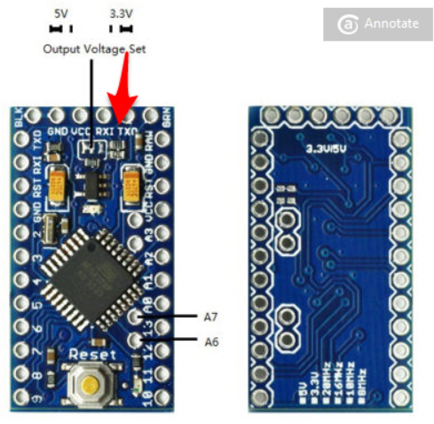
@jovo I had some problems with mini's I ordered which can be "switched" between 3.3 and 5v. These mini's use a voltage divider that consumes around 2 mA.! Apart from the led and regulator I alse needed to remove this divider to get to less consumption.
-
@jovo I had some problems with mini's I ordered which can be "switched" between 3.3 and 5v. These mini's use a voltage divider that consumes around 2 mA.! Apart from the led and regulator I alse needed to remove this divider to get to less consumption.
@AWI: Tx for the feedback. I checked with my mini's. I got both versions: 5v and 3v3 (ordered from BEEStore). They seems not to be switchable. they 3v3 one have a 8Mhz crystal and the regulator (AMS 1117) for 3v3. the 5v one has 16Mhz crystal and a 5v version of this regulator.
I was wondering, in my design I plan to power the board directly from the VCC pin (not the raw). I suspect that the regulator doesn't consume much in this case. let me see if I can find a datasheet of this component.
-
Humm, from the AMS1117 datasheet:
Quiescent Current AMS1117: 5-11mA.
It looks like to has some significant quiescent current.
Perhaps for me good idea to research a little further in this direction. -
@Jan-Gatzke Thank you very much Sir....Now this is getting excited :+1:
@Jan-Gatzke i've tried this bootloader with several of my arduino pro mini.
most of them run @ 1 Mhz, thanks to you. but somehow the current consumption dont decrease. but i've check with my usbtiny for the fuse, it already @ 1MHz....no clue what happen here
-
@jovo I had some problems with mini's I ordered which can be "switched" between 3.3 and 5v. These mini's use a voltage divider that consumes around 2 mA.! Apart from the led and regulator I alse needed to remove this divider to get to less consumption.
-
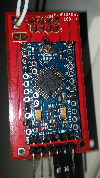
@AWI Hello AWI, sorry i know the topic is old, but i have exatly the same minis bought. Can you tell me what i have to remove or can you attach a photo. many thanks
greetings
hansiii -
@hansiii that was certainly a while ago.. I removed all resistors near the voltage selector and the regulator (5 legs)
Hello! It looks like you're interested in this conversation, but you don't have an account yet.
Getting fed up of having to scroll through the same posts each visit? When you register for an account, you'll always come back to exactly where you were before, and choose to be notified of new replies (either via email, or push notification). You'll also be able to save bookmarks and upvote posts to show your appreciation to other community members.
With your input, this post could be even better 💗
Register Login