Anyone using/tried the E28-2G4M27S 2.4Ghz LoRa SX1280 27dB module?
-
I just now noticed that Andreas Spiess did a youtube about the same chip, though different model Ebyte modue:
#323 Connected Light Sensor with 2 4GHz LoRa: How is its range? (SX1280, Arduino, ESP32) – 13:11
— Andreas SpiessSmall world: it turns out he also made a breakout board for himself in order to test the module. It doesn't look pin compatible with my module, however, as it has only 14 pins on its pinout, whereas mine has 16. Also, not sure whether Andreas posted his breakout board anywhere. I would expect so. He has a github, but it has almost no descriptive material in it other than the titles, so it's hard to know what is truly what.
Worthy of note: the module he chose is less capable than the one I picked: substantially less potential transmit power, and also, according to Ebyte specs, somewhat inferior receive sensitivity.
Fortunately, he does post links to the libraries that he used to operate the SX1280 chip, so that's probably a good starting point, or at least a point of comparison.
To avoid interference he does report having to turn off the wifi on his esp32 that's driving the module, so having an ethernet connection for the gateway probably makes the most sense. The good news is that with LoRa, you should need only one such gateway, and you can probably put it just about anywhere and still have a good, solid RF connection to your nodes. Probably a raspberry pi could serve that purpose for a low effort solution, though I may go for an arduino-ethernet solution because that may turn out to be even easier, and probably without the need for ongoing updates and security maintenance. i.e. it should "just work". Perhaps setting the target IP address with a dipswitch would avoid any future need to revisit the firmware. Also, a raspberry pi's attack surface seems orders of magnitude larger than a more basic, hardware oriented solution.
Regardless, the next step for me is to wire it up and get it to play ping pong with another node. Then I'll be able to quickly determine whether ambient wi-fi signals in the environment will be a cause for concern or not. I suspect not, but sending thousands/millions of test packets while measuring for packet loss will tell the tale definitively.
I have one node with a 100uF capacitor (pictured in my preceding post), and another node without, so I'll try to determine whether it makes any practical difference or not. I'm guessing that it were powered by a coincell, it's essential, but if by two AA's in close proximity, probably not (though if the batteries are weak, maybe it would, at the margin, still help).
-
@NeverDie this video is very useful
@Parkeexant said in Anyone using/tried the E28-2G4M27S 2.4Ghz LoRa SX1280 27dB module?:
@NeverDie this video is very useful
Which video?
-
@ejlane said in Anyone using/tried the E28-2G4M27S 2.4Ghz LoRa SX1280 27dB module?:
@NeverDie Okay, sounds like you know more than I do about it, I guess. I was sure that I had gotten responses/work done on a weekend, but maybe my memory is just faulty.
But yes, their service is very impressive. And for a 2 layer board, I can get it delivered here on the west coast USA in usually 6 calendar days from ordering with the quickest shipping. That's shockingly quick, and faster than most local places can even just make the board. (Well faster than any that I know of. I've pretty much switched to only using JLCPCB. Hardly even bother quoting other places these days.)
In pre-pandemic times, I could order on a Monday from allpcb.com and get my order delivered by Friday here in the US. These days... not sure if that's true anymore, as I haven't ordered from them since before the pandemic.
I believe if you really needed a bunch, they would be a decent price even with the penalties. Every time I've had to pay an extra charge for something, it was a reasonable amount. Though I've never tried to order 100 of anything through them, so I could be wrong.
Eric basically said "Please don't panelize" and that it wouldn't save money. Now I think I understand why: if you do a lousy job of either the vgrooving or mouse bites, it's going to interfere with their manufacturing process. e.g. maybe that part of their much larger project board shatters to bits during fabrication because it's too weak structurally. It's much better for them (at least from their cost of business) to be in complete control of it. Otherwise, some engineer might have to remediate somebody's poor panelization, which takes extra time and throws a wrench into their work flow.
@NeverDie I've only done my own panelization maybe 2 or 3 times ever. Usually just leave it to the board house, but 10 or so years ago, before the board houses were quite this cheap and I was on more of a budget because of saving for a down payment, I did try it out for some personal projects as an experiment.
But I didn't even try to do v-grooves. Not sure if whichever one I was using would even allow it. I just left extra room between the active parts of the board on the PCB and literally took tin snips and cut them apart with that. With 1 cm between boards it's easy to not hit anything.
Obviously doing it like that wouldn't weaken their board, but if you need precise board shape/size then this wouldn't do it. Ever since then the prices have gotten so low that I don't bother trying. I would be interested knowing what about JLCPCB's process makes them want to limit any order to the 30 pieces. That's always seemed a bit weird to me. I would think they would welcome the extra volume/money.
But weirdly enough, I don't even know where to go for larger orders. I mean, I can do a search like anyone else, but I don't have direct experience. By the time it gets to that qty, then the assembly house deals directly with whoever they work with to get the boards made. At that point it's not me dealing with them directly, except for passing requirements to the client, who then passes them to the assembly house, etc.
I've also entered some of their limitations into KiCad, but I'm not sure if I did a complete job of it. I try to be a bit more conservative than being right at the manufacturable edge. But yeah, get the rules to catch as much as possible. I think my problems came in when I did something that such a minor change I didn't even really think about running the rules again, and of course something like that is usually harmless, but every once in a while it does something unexpected, so obviously the rules need to be checked after every change, and every time before exporting gerbers for manufacturing. And I try to do that, but still these days I'm sure that are times that I forget.
-
Anyhow, back to the project at hand. I completed design of two different barebones mcu boards (one is just atmega328p and the other allows an Arduino pro mini to dock with it instead) that are 2xAA battery powered:
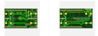
Given the wait time from a PCB fab, I went with two different designs just in case I made an error and one of them doesn't work. They both have identical test points where I can separately monitor current consumed by the mcu vs current consumed by the radio--all the better to tease apart what's really going on. Then I also have five different radio shields that fit either mcu board exactly the same:
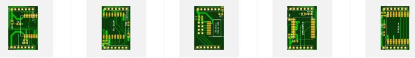
As JLPCB doesn't work on weekends, I'm going to design a few more boards and then submit them all on Sunday night. When they finally do arrive in the mail, I'll not only be better able to evaluate the E28-2G4M27S (because the new design should practically eliminate any hardware noise), but also compare the following radios against one another for their relative performance on the exact same platform: 2.4Ghz E28-2G4M27S, three different kinds of 915Mhz SX1262 LoRa, a number of different kinds of 2.4GHz nRF24L01 (all with PA and LNA to put them on the same playing field as the other radios in the round-up), a 915Mhz RFM69HW, and a 400Mhz Ra-01 LoRa. Of interest to me are what makes for a reliable "worst case" range in my home environment at different transmission power levels and if anything stands out as a clear winner in terms of energy efficiency for bits that are reliably delivered. By worst case, I mean transmitting from behind a cement footer almost 6 feet beneath grade to a second story room across the house diagonally at the point furthest from it. If transmissions can work reliably along that transmission path, then they're probably good between any other two points in the house as well. There is, for instance, no way that a bog standard nRF24L01 could deliver any packets along that path, because its transmit power is just 0dB. However, with appropriate "boosting" via PA and LNA, I think it has a chance. In comparison, I previously tested the 400Mhz LoRa along this path, and it worked without a hitch. Matter of fact it could reach a quarter mile (or better) in all directions outside the house as well using just the default parameters in the old RadioHead libraries. I'll try that test again, but this time with the new library to see if it fares any differently this time around, as well as try LoRa at 915Mhz and 2.4Ghz.
Depending on how the testing goes, I may leverage the same platform to also try out some other inexpensive radio modules that I've seen on Aliexpress that, up to now, I've lacked an easy way to comparison test. For instance, some featuring radio chips made by Texas Instruments (CC1101, CC1310, CC1352, CC1120, CC2450, CC2640, CC2650, and a whole slew of others) and some featuring radio chips made by Silicon Labs (e.g. Si4463). If you know of chips that you're keen to try, let me know and maybe I can try them for you in a way that will be meaningful because of the comparisons. I'm not expecting that big differences will emerge that aren't already known, but testing will cut through the marketing propaganda and (hopefully) reveal the truth.
@NeverDie said in Anyone using/tried the E28-2G4M27S 2.4Ghz LoRa SX1280 27dB module?:
If you know of chips that you're keen to try, let me know
Since you asked, maybe look at the good-old cheap 433 MHz transmitter/receivers? Maybe you are sticking to transceivers so this wouldn’t fly. Or maybe you are staying away from ASK modulations. I’m sure these cheapo radios won’t pass your fundaments concrete/cross-house test, but it would be another data point. This season I’ve been slowly reworking my limited 433 MHz home network of motion detectors. Having failed to transmit through concrete/cross-house pathways, I built some 433 repeaters that successfully worked on a line-of-site pathways that allowed me to look around the corners. I have found these TX radios & SR501 motion detectors just sip energy and my 4-pack of AA batteries last for, in some cases, over 3 years.
As you are working with JLCPCB are you using them for assembly? I did so last year with different project and had really good results. I did have some difficulty finding compatible components, so I suspect that they won’t be able to resource all your radios… but that was some time ago and I have much to learn. I look forward to doing more assembly with JLCPCB. It was also really inexpensive and a great way to get around my poor home soldering quality.
[edit: forgot to say, @NeverDie and everyone else: What a great thread. Thanks for building and sharing. I have learned much here.]
-
@NeverDie said in Anyone using/tried the E28-2G4M27S 2.4Ghz LoRa SX1280 27dB module?:
If you know of chips that you're keen to try, let me know
Since you asked, maybe look at the good-old cheap 433 MHz transmitter/receivers? Maybe you are sticking to transceivers so this wouldn’t fly. Or maybe you are staying away from ASK modulations. I’m sure these cheapo radios won’t pass your fundaments concrete/cross-house test, but it would be another data point. This season I’ve been slowly reworking my limited 433 MHz home network of motion detectors. Having failed to transmit through concrete/cross-house pathways, I built some 433 repeaters that successfully worked on a line-of-site pathways that allowed me to look around the corners. I have found these TX radios & SR501 motion detectors just sip energy and my 4-pack of AA batteries last for, in some cases, over 3 years.
As you are working with JLCPCB are you using them for assembly? I did so last year with different project and had really good results. I did have some difficulty finding compatible components, so I suspect that they won’t be able to resource all your radios… but that was some time ago and I have much to learn. I look forward to doing more assembly with JLCPCB. It was also really inexpensive and a great way to get around my poor home soldering quality.
[edit: forgot to say, @NeverDie and everyone else: What a great thread. Thanks for building and sharing. I have learned much here.]
@Larson said in Anyone using/tried the E28-2G4M27S 2.4Ghz LoRa SX1280 27dB module?:
As you are working with JLCPCB are you using them for assembly? I did so last year with different project and had really good results. I did have some difficulty finding compatible components, so I suspect that they won’t be able to resource all your radios… but that was some time ago and I have much to learn. I look forward to doing more assembly with JLCPCB. It was also really inexpensive and a great way to get around my poor home soldering quality.
Good idea. I haven't tried it, because I've been locked in a mindset of using radio modules, in which case soldering things is easy enough that I can do it myself manually without much effort. But for small, fine pitched chips (the kind I've been avoiding for just that reason), it sounds like a worthwhile thing to try. Maybe I could use better components than are typically found in aliexpress modules as well. :grinning:
-
@NeverDie said in Anyone using/tried the E28-2G4M27S 2.4Ghz LoRa SX1280 27dB module?:
If you know of chips that you're keen to try, let me know
Since you asked, maybe look at the good-old cheap 433 MHz transmitter/receivers? Maybe you are sticking to transceivers so this wouldn’t fly. Or maybe you are staying away from ASK modulations. I’m sure these cheapo radios won’t pass your fundaments concrete/cross-house test, but it would be another data point. This season I’ve been slowly reworking my limited 433 MHz home network of motion detectors. Having failed to transmit through concrete/cross-house pathways, I built some 433 repeaters that successfully worked on a line-of-site pathways that allowed me to look around the corners. I have found these TX radios & SR501 motion detectors just sip energy and my 4-pack of AA batteries last for, in some cases, over 3 years.
As you are working with JLCPCB are you using them for assembly? I did so last year with different project and had really good results. I did have some difficulty finding compatible components, so I suspect that they won’t be able to resource all your radios… but that was some time ago and I have much to learn. I look forward to doing more assembly with JLCPCB. It was also really inexpensive and a great way to get around my poor home soldering quality.
[edit: forgot to say, @NeverDie and everyone else: What a great thread. Thanks for building and sharing. I have learned much here.]
@Larson said in Anyone using/tried the E28-2G4M27S 2.4Ghz LoRa SX1280 27dB module?:
@NeverDie said in Anyone using/tried the E28-2G4M27S 2.4Ghz LoRa SX1280 27dB module?:
If you know of chips that you're keen to try, let me know
Since you asked, maybe look at the good-old cheap 433 MHz transmitter/receivers? Maybe you are sticking to transceivers so this wouldn’t fly. Or maybe you are staying away from ASK modulations. I’m sure these cheapo radios won’t pass your fundaments concrete/cross-house test, but it would be another data point. This season I’ve been slowly reworking my limited 433 MHz home network of motion detectors. Having failed to transmit through concrete/cross-house pathways, I built some 433 repeaters that successfully worked on a line-of-site pathways that allowed me to look around the corners. I have found these TX radios & SR501 motion detectors just sip energy and my 4-pack of AA batteries last for, in some cases, over 3 years.
Interesting idea. I'll have to give that one some thought. A lot of the cheap wireless temperature-humidity sensors seem to use ASK, and I've never been clear as to why. e.g. Oregon Scientific, and similar companies. There are a number of hacker-type projects aimed at receiving and decoding those signals precisely because the wireless sensors are so cheap. And those cheap wireless key-finder fobs I think may use it as well. Maybe the receiver current can be extremely low? Those fobs always have to be listening for a wireless signal. All I know is that low frequency implies less energy consumption by whatever oscillator is being used.
-
@Larson said in Anyone using/tried the E28-2G4M27S 2.4Ghz LoRa SX1280 27dB module?:
@NeverDie said in Anyone using/tried the E28-2G4M27S 2.4Ghz LoRa SX1280 27dB module?:
If you know of chips that you're keen to try, let me know
Since you asked, maybe look at the good-old cheap 433 MHz transmitter/receivers? Maybe you are sticking to transceivers so this wouldn’t fly. Or maybe you are staying away from ASK modulations. I’m sure these cheapo radios won’t pass your fundaments concrete/cross-house test, but it would be another data point. This season I’ve been slowly reworking my limited 433 MHz home network of motion detectors. Having failed to transmit through concrete/cross-house pathways, I built some 433 repeaters that successfully worked on a line-of-site pathways that allowed me to look around the corners. I have found these TX radios & SR501 motion detectors just sip energy and my 4-pack of AA batteries last for, in some cases, over 3 years.
Interesting idea. I'll have to give that one some thought. A lot of the cheap wireless temperature-humidity sensors seem to use ASK, and I've never been clear as to why. e.g. Oregon Scientific, and similar companies. There are a number of hacker-type projects aimed at receiving and decoding those signals precisely because the wireless sensors are so cheap. And those cheap wireless key-finder fobs I think may use it as well. Maybe the receiver current can be extremely low? Those fobs always have to be listening for a wireless signal. All I know is that low frequency implies less energy consumption by whatever oscillator is being used.
@NeverDie: Yes, as you describe elswere, and taught me, the design trade-off parameters are frequency, bandwith, dwell time, bit transfer rate, power demand, and most importantly, range. I'm looking forward to your findings.
Regarding the low reciever current: don't know about the FOB's but I have found the transmitter power to be key. My design has the "always on" reciever connected to mains. so I don't worry about that power. But the battery-limited transmitter devices are brought to life and triggered by the signal pin of the SR501 sensors that is high enough, long enough to complete a transmission, or several. The HT12E (encoder) chip is connected to the SR501 pin is fired and sends the settings of the dip-switch pin hi/low settings that is recieved by the always-on HT12d (decoder) that the Atmega 328PU can understand. I think the HT devices are MCUs in a different form, like what I imagine a FPLC to be like... don't know for sure. Why do I drone on? Because of the HT12D and HT12E pariings are very specific and very low on power demand due to their design. When I built my configuration (6 years ago) I knew more than I do now. But I'm relearning more. Andreas Spiess, Great Scott, Big Clive, and YOU, explore this stuff extensively, and I thank you all.
In summary, my repeaters and base RX station are mains powered so I don't worry about power & batteries. The primary focus for conservation of batteries is on the TX/Motion devices. Everything downstream of TX is mains powered or can be suitably backed up in the short term.
-
I think I'll pass on the ASK, and the reason is that it tends to be noise/interference sensitive. The usual workaround for noise/interference by ASK garage door openers, for instance, is to send the same packet multiple times, with the hope that at least one of them will get through. Well, I suppose that strategy works "good enough" in some sense for that application, but I'd say that all those extra packets being sent is a waste of energy for a battery powered sensor application that's transmitting, say, once every 5 minutes. On the other hand, if it doesn't really matter if you lose packets from time to time (e.g. a wireless TH sensor), maybe you don't need to send multiple redundant packets in the hopes that one gets through. That said, IIRC, Oregon Scientific TH sensors send their packets in triplicate. Well, that's my off-the-cuff take on it. Feel free to disagree if I'm missing something important.
Anyhow, I think that's why one tends to see ASK being used at 433Mhz: it's a relatively clean channel, so the noise/interference isn't as big a factor as it would be at 915Mhz or certainly 2.4Ghz.
At the end of the day, I think ASK was popular because, historically, it was easy and cheaper to make. Think 1940's, 1950's, and maybe 1960's, before integrated circuits. Now that FSK, its main competitor, is widespread and cheap anyway, I just don't see much benefit in reverting to old school ASK unless maybe you're manufacturing millions of something and want to save every penny possible. Because of the possible noise issue, you're also limited to slower bit rates with ASK than the alternatives, which, in turn, also lead to longer transmit times.
P.S. Build time at JLCPCB is now running 2-3 days. Out of the 10 boards I submitted on Sunday (China time), 9 are still awaiting "data preparation." Only 1 of the 10 is currently in production. I think they're manpower limited right now, maybe because of China's zero-tolerance covid policy.
@NeverDie Yes, you are correct: the HT12D datasheet indicates that multiple signals must be recieved before the enable pin is activated. I think the 'multiple' is a count of three and there is probably a preamble in advance of the main message of high/low settings. The transmitter, again I think, just keeps sending the message until the SR501 drops power (2 seconds on the minimum settings). I get alot of double hits because of this. Good to know about the noise and history. Thanks.
-
@NeverDie Yes, you are correct: the HT12D datasheet indicates that multiple signals must be recieved before the enable pin is activated. I think the 'multiple' is a count of three and there is probably a preamble in advance of the main message of high/low settings. The transmitter, again I think, just keeps sending the message until the SR501 drops power (2 seconds on the minimum settings). I get alot of double hits because of this. Good to know about the noise and history. Thanks.
@Larson said in Anyone using/tried the E28-2G4M27S 2.4Ghz LoRa SX1280 27dB module?:
@NeverDie Yes, you are correct: the HT12D datasheet indicates that multiple signals must be recieved before the enable pin is activated. I think the 'multiple' is a count of three and there is probably a preamble in advance of the main message of high/low settings. The transmitter, again I think, just keeps sending the message until the SR501 drops power (2 seconds on the minimum settings). I get alot of double hits because of this. Good to know about the noise and history. Thanks.
Worthy of note is, as you may already know, you can skip the HT12D and HT12E altogether if you're driving it from an Arduino. You can do all the encoding/decoding in software, and all you need on the transmit side is a mosfet to control the on/off of the transmit on the transmitter. I did this once by rolling my own software to do it, but I think it may also be handled in the wire library, IIRC. On the receiver side, I got better results by upgrading to an Arduino Due, because it has 12 bit instead of 10 bit Analog-to-digital converter, and a faster speed to do the processing. However, maybe I could have done it all digital and skipped that. I was just trying to eek the most reception I could out of possibly weak signals.
Fun fact: on a 900Mhz Raspberry Pi (Version 1), you can make a 900Mhz radio transmitter just by putting a wire of appropriate length in one of the GPIO pins and then toggling PWM to it at the 900Mhz clock cycle. Of course, you'll need something more sensitive on the receive side. This would be an ASK scheme, by the way.
Also, fun fact: the speed on the Due is fast enough that light (radio waves) doesn't move all that far per clock cycle, so you can detect when signals arrive directly between transmitter and receiver from an on-pulse, and you can also detect fainter echoes of that same pulse arriving later because they've bounced off a wall or something and took a longer path between the transmitter and receiver. I thought that was kinda cool, because I ordinarily think of the speed of light as being more or less instant in such close quarters. Anyhow, I forgot the name for this kind of temporal transmit "smearing", but it's a very real effect where the transmitter kinda interfers with itself, so to speak, because of the layout of reflecting surfaces in the environment. [Edit: just now looked it up. "Multipath interference" is the term. MIMO thrives on multipath signals, but it's a problem for regular radio to deal with it--though, as you'd expect, there are all kinda of ways to handle it; the easiest being just putting a long enough time interval after an ON pulse for the echoes to die out to background noise levels. ] :-)
P.P.S. All 10 of my JLCPCB boards are now in production, though it is now technically early Tuesday morning in China. Looking at the time stamps, the production process itself appears to run around the clock, not just during daytime business hours, so that's good. Hopefully that means there's no complicating factor left standing in the way of completing the production and shipping it.
-
@NeverDie : Very interesting stuff. Even at the lowly 8MHz, the speed of processing pretty much blows away the human concept of time. Fun to hear of the Raspberry and Due. I’ll have to play with those.
HT12D/HT12E: Yes, I learned that the processing could be done on a MCU and I did that on the repeaters I built. I put a Pro-Mini in between a 433 Mhz RX and TX. This repeater sits and listens in the RX mode until it is pinged with a transmission from one of the 433-HT12E detectors. Once a message comes in, the MCU then switches to TX mode and passes the message along, then reverts to listening again. The repeaters and the base station are mains powered as I figured the always ON state would be a battery killer whereas the 433-HT12E’s are very low power and outfitted with batteries.
Rather than using the IIRC library I used RCSwitch – probably because I found that first. RadioHead was another option. The biggest challenge for me was learning which protocol to use for the 433 radios. The command mySwitch.setProtocol(11); did the trick.
@Larson The Due has an 84Mhz clock speed, making it easier to spot the effect. These days you could save some coin by using an ESP8266 (80Mhz) or even faster ESP-32, not to mention the crazy fast Teensy 4.1 (600Mhz). At 600Mhz, light moves only 20 inches per clock cycle. Pretty cool for cheap parts, isn't it? :-)
-
I received the Dorji parts I had ordered. They arrived very fast and very well packed. I got them on ebay, but for comparison I'm still waiting on everything else that I had ordered from aliexpress.
It turns out it took 3 days for JLCPCB to build my simple 2 layer PCB's. Either they're overwhelmed with business or understaffed. With any luck they'll ship out tomorrow, so probably another week to get here.
Meanwhile I received a Nord PPK2 Power Profiler, as I found a seller who briefly had some in stock. So, I'll be putting that to use to accurately compare current consumption of the various test builds after the PCBs eventually arrive from JLPCB. Meanwhile, I may try it out on an ESP8266 to finally get some solid current consumption numbers on how much power it takes to wake-up into ESP-NOW mode from a cold start. If it's good, then maybe so-called trigger boards will bring the ESP8266 back to life as a low power competitor. Also, I'm really curious as to how sensitive (or not) the ESP8266 2.4Ghz ESP-NOW communications will be to interference in a home environment that, at least so far, seems to have shredded 2.4Ghz LoRa. According to the labeling on the tin, they come with 25dBa power amplifiers, so I expect they'll do far better than a bog standard nRF24L01, which has a maximum of only just 0dBa transmit power. Of course, when you add in the cost of a trigger board, then total cost may (?) turn out to be a wash compared to other mcu/radio combos that don't require a trigger board. We'll see!
-
@samh Great stuff! I look forward to hearing more. As you probably know, the buck/boost converter (whichever it is) that's in your photo is a possible source of noise. I can't say whether, in reality, it would be or not. That's one of the reasons why (below), I'm planning to run directly from batteries only.
@Larson Good suggestions. I decided to dump the pro mini idea and just make my own barebones pro mini, because pro mini's come with three things that aren't useful and actually get in the way: 1. the LDO, 2. the oscillator, and 3. the LED on pin 13. I'm hoping (but haven't confirmed) that by eliminating the oscillator on pins D20 and D21, I can use those pins to drive two LED's kinda "for free" since nobody uses those pins for anything. So, the first draft looked like this:
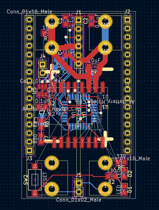
to get the shortest possible lines, like you said. It also includes a TPL5010 as an ultra low current wakeup timer. The main thing, though, is that it runs from two AA batteries, which are directly attached to the PCB itself. Well, this design was working out fine, but it seemed a bit tedious to redo it for each possible radio I wanted to test, so I think I'm settling on this instead as a test platform:
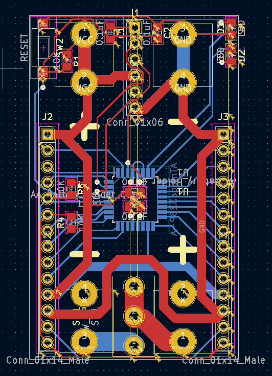
which amounts to a stripped down pro mini (plus two I2C pinsout at the bottom for plugging in a TH sensor, or whatnot). In this case, the idea is to do a simple breakout board for each radio and connect it as a shield to the unused pins on the atmega328p. I figure it should be easier than doing a complete, fully integrated board for each radio. And I like that it's of minimal size (the footprint of two AA batteries), yet packs enough power that I expect it should have no trouble supplying even 200ma if needed just from the batteries themselves.I'm lucky in that I have a Dragon programmer, so I can both burn the bootloader and set the fuses on the atmega328p prior to soldering it into place on the PCB. From past experience, the sleep current on the atmega328p itself can be as low as 100na. In the past when Pro Mini's sold for only a buck, I leaned toward using Pro Mini's for everything. These days I guess I'll roll my own.
I think eventually I want to replace the canonical 6 pin FTDI connection with a 5 pin picoblade. I've only just started looking into that. I was favoring the idea of using 1.0mm pitch JST-SH conectors for the task, but sourcing them didn't look easy. So, I'm reluctantly settling on the 1.25mm pitch picoblade instead. If there exists something even more compact (maybe some kind of 2x3 row of pins on a connector), then I'd be keen to hear what it is.
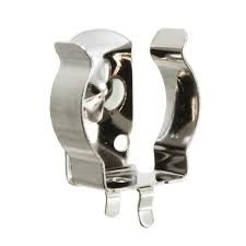
The AA battery connectors are the Keystone 92, which look like this:
In the end, it might look like an improved variation of one of these:
https://www.openhardware.io/view/395/LoRa-Ra-01-ATmega328P-Node
https://www.openhardware.io/view/268/Arduino-Pro-Mini-Shield-for-RFM69HW
https://www.openhardware.io/view/480/Compact-nRF24L01-Pro-Mini-Bottom-Shield
but this time a bit more of a general purpose razor and blades system, if you catch my meaning. This time it will be a little wider than a pro mini, so it will be possible to fit any radio onto the shield. That said, I always liked the simplicity and ease of assembly of the "LoRa Ra-01 ATmega328P node". Perhaps the biggest improvement is the tight integration of the batteries, which in most designs are left "flapping in the breeze" as an afterthought for the builder to sort out.Anyhow, I have a bit more work to do, but that's the current evolution. As always, any thoughts, reactions, suggestions, or feedback appreciated.
@NeverDie said in Anyone using/tried the E28-2G4M27S 2.4Ghz LoRa SX1280 27dB module?:
I'm hoping (but haven't confirmed) that by eliminating the oscillator on pins D20 and D21, I can use those pins to drive two LED's kinda "for free" since nobody uses those pins for anything.
Reporting back: I have the answer. It turns out that the standard arduino core for atmega328p that's baked into the standard Arduino IDE does not support Arduino pins 20 and 21 as digital GPIO pins for driving LEDs. However, the good news is that there's an even better Arduino core, called MCUDude MiniCore which does support exactly those pins for such purposes. Here's the TL;DR:
This core gives you two extra IO pins if you're using the internal oscillator! PB6 and PB7 is mapped to Arduino pin 20 and 21.
https://mcudude.github.io/MiniCore/package_MCUdude_MiniCore_index.json
It's very easy to use. You can install it into the regular Arduino IDE, pick from among the MiniCore "boards" in the board manager, select the 8Mhz option and a few other obvious options, and then you're done with instalation. From that point on your code will automagically compile using MiniCore. Just to be sure, I gave it a try myself, and I'm now blinking a blue LED off of Ardino Pin 20. It works! -
@NeverDie said in Anyone using/tried the E28-2G4M27S 2.4Ghz LoRa SX1280 27dB module?:
I'm hoping (but haven't confirmed) that by eliminating the oscillator on pins D20 and D21, I can use those pins to drive two LED's kinda "for free" since nobody uses those pins for anything.
Reporting back: I have the answer. It turns out that the standard arduino core for atmega328p that's baked into the standard Arduino IDE does not support Arduino pins 20 and 21 as digital GPIO pins for driving LEDs. However, the good news is that there's an even better Arduino core, called MCUDude MiniCore which does support exactly those pins for such purposes. Here's the TL;DR:
This core gives you two extra IO pins if you're using the internal oscillator! PB6 and PB7 is mapped to Arduino pin 20 and 21.
https://mcudude.github.io/MiniCore/package_MCUdude_MiniCore_index.json
It's very easy to use. You can install it into the regular Arduino IDE, pick from among the MiniCore "boards" in the board manager, select the 8Mhz option and a few other obvious options, and then you're done with instalation. From that point on your code will automagically compile using MiniCore. Just to be sure, I gave it a try myself, and I'm now blinking a blue LED off of Ardino Pin 20. It works!@NeverDie More good information - thanks for posting. Good work on finding the alternate core. I have a couple of questions:
- By “trigger board”, are you referring to the TPL5010 discussed above? (Adafruit carries the TPL5110, I think.) Is the idea here to power and de-power the radio, or mcu, to discover the rock-bottom minimum current requirement?
- What are you sacrificing when not using the external crystal? And to do this, are you setting fuses to tell the 328 to use the internal crystal? I've found setting fuses to be a complicated affair.
-
@Larson The Due has an 84Mhz clock speed, making it easier to spot the effect. These days you could save some coin by using an ESP8266 (80Mhz) or even faster ESP-32, not to mention the crazy fast Teensy 4.1 (600Mhz). At 600Mhz, light moves only 20 inches per clock cycle. Pretty cool for cheap parts, isn't it? :-)
@NeverDie said in Anyone using/tried the E28-2G4M27S 2.4Ghz LoRa SX1280 27dB module?:
At 600Mhz, light moves only 20 inches per clock cycle. Pretty cool for cheap parts, isn't it?
Yes, mind-blowing. I got into this hobby via the Parallax Basic kits. The second MCU I bought from them was about $60 and I thought that was stunning. So when I found the ATTINY85 I was addicted, if only because the access to this technology costs less than a cup of coffee. The progression to Arduinos and ESP's was a natural extension for this cheap hobby.
-
@NeverDie More good information - thanks for posting. Good work on finding the alternate core. I have a couple of questions:
- By “trigger board”, are you referring to the TPL5010 discussed above? (Adafruit carries the TPL5110, I think.) Is the idea here to power and de-power the radio, or mcu, to discover the rock-bottom minimum current requirement?
- What are you sacrificing when not using the external crystal? And to do this, are you setting fuses to tell the 328 to use the internal crystal? I've found setting fuses to be a complicated affair.
@Larson said in Anyone using/tried the E28-2G4M27S 2.4Ghz LoRa SX1280 27dB module?:
@NeverDie More good information - thanks for posting. Good work on finding the alternate core. I have a couple of questions:
-
By “trigger board”, are you referring to the TPL5010 discussed above? (Adafruit carries the TPL5110, I think.) Is the idea here to power and de-power the radio, or mcu, to discover the rock-bottom minimum current requirement? - What are you sacrificing when not using the external crystal? And to do this, are you setting fuses to tell the 328 to use the internal crystal? I've found setting fuses to be a complicated affair.
Good questions!
- Yes, by "trigger board", the adafruit tpl5110, or something like it, is what I have in mind. The goal would be zero leakage current beyond the ~40 nanoamps of management overhead. I don't know if the p-channel mosfet design in adafruit's tpl5110 breakout board achieves zero leakage (or near enough),but it would be worth measuring. I think Kevin Darrah may be the one who coined the term "trigBoard". His design is a lot more elaborate and, I assume, costly: https://www.kevindarrah.com/wiki/index.php?title=TrigBoardV7
Is the idea here to power and de-power the radio, or mcu, to discover the rock-bottom minimum current requirement?
Yes. It's a little more complicated though, because generally the mcu/radio wake-up time is much longer from a cold start than from a deep sleep, so the real objective would be to find the breakeven point at which power-off is the better choice (i.e. how long does the duty cycle need to be).
What are you sacrificing when not using the external crystal?
Accuracy. If you were interfacing to something that had extremely tight timing requirements, the crystal would be more accurate. In practice, I haven't ever noticed a difference in anything that I've done.
And to do this, are you setting fuses to tell the 328 to use the internal crystal? I've found setting fuses to be a complicated affair.
Yes, I set the fuses. Currently I use the following fuse settings:
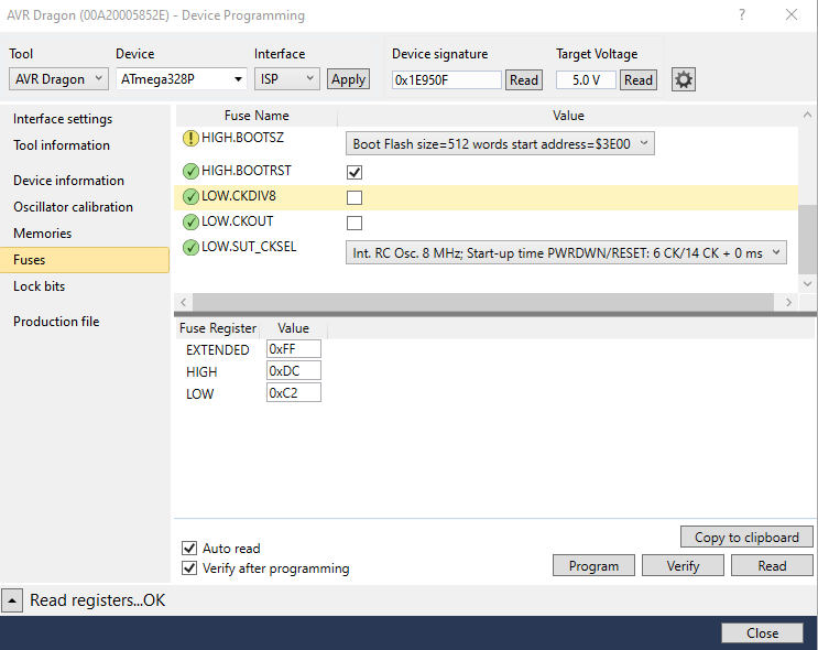
By running from the 8Mhz internal oscillator and sleeping, not only can you sleep the atmega328p at just 100na, but as a bonus the atmega328p can wake up in just 3 microseconds (I previously measured it with an oscilloscope, so that number is solid). For being such an old mcu, the atmega328p can be amazingly high performance when it comes to saving power. This becomes of greater relevance if you're getting your power by harvesting weak energy sources.If you want to play around with setting fuse bits, the standard advice is to leave the Extended bits alone until you know what you're doing. Even then, there's probably no need to change them. It's the High and Low bits that are of relevance.
A great source of information is: https://www.gammon.com.au/power
-
@Larson said in Anyone using/tried the E28-2G4M27S 2.4Ghz LoRa SX1280 27dB module?:
@NeverDie More good information - thanks for posting. Good work on finding the alternate core. I have a couple of questions:
-
By “trigger board”, are you referring to the TPL5010 discussed above? (Adafruit carries the TPL5110, I think.) Is the idea here to power and de-power the radio, or mcu, to discover the rock-bottom minimum current requirement? - What are you sacrificing when not using the external crystal? And to do this, are you setting fuses to tell the 328 to use the internal crystal? I've found setting fuses to be a complicated affair.
Good questions!
- Yes, by "trigger board", the adafruit tpl5110, or something like it, is what I have in mind. The goal would be zero leakage current beyond the ~40 nanoamps of management overhead. I don't know if the p-channel mosfet design in adafruit's tpl5110 breakout board achieves zero leakage (or near enough),but it would be worth measuring. I think Kevin Darrah may be the one who coined the term "trigBoard". His design is a lot more elaborate and, I assume, costly: https://www.kevindarrah.com/wiki/index.php?title=TrigBoardV7
Is the idea here to power and de-power the radio, or mcu, to discover the rock-bottom minimum current requirement?
Yes. It's a little more complicated though, because generally the mcu/radio wake-up time is much longer from a cold start than from a deep sleep, so the real objective would be to find the breakeven point at which power-off is the better choice (i.e. how long does the duty cycle need to be).
What are you sacrificing when not using the external crystal?
Accuracy. If you were interfacing to something that had extremely tight timing requirements, the crystal would be more accurate. In practice, I haven't ever noticed a difference in anything that I've done.
And to do this, are you setting fuses to tell the 328 to use the internal crystal? I've found setting fuses to be a complicated affair.
Yes, I set the fuses. Currently I use the following fuse settings:
By running from the 8Mhz internal oscillator and sleeping, not only can you sleep the atmega328p at just 100na, but as a bonus the atmega328p can wake up in just 3 microseconds (I previously measured it with an oscilloscope, so that number is solid). For being such an old mcu, the atmega328p can be amazingly high performance when it comes to saving power. This becomes of greater relevance if you're getting your power by harvesting weak energy sources.If you want to play around with setting fuse bits, the standard advice is to leave the Extended bits alone until you know what you're doing. Even then, there's probably no need to change them. It's the High and Low bits that are of relevance.
A great source of information is: https://www.gammon.com.au/power
@NeverDie said in Anyone using/tried the E28-2G4M27S 2.4Ghz LoRa SX1280 27dB module?:
sleep the atmega328p at just 100na
Wow, that is pretty close to zero in my view. Consider battery self-discharge in comparison: I use 18650 LiOn batteries in most of my projects. Say a 2000 mAh battery loses 1%/month in self discharge s(ome say it is much higher). Well, the math, if I did it right, shows a self-discharge of about 25 uA. So sleeping at 100nA is really impressive.
Thanks for the fuse guidance. I will employ this next chance I get.
-
-
@NeverDie said in Anyone using/tried the E28-2G4M27S 2.4Ghz LoRa SX1280 27dB module?:
sleep the atmega328p at just 100na
Wow, that is pretty close to zero in my view. Consider battery self-discharge in comparison: I use 18650 LiOn batteries in most of my projects. Say a 2000 mAh battery loses 1%/month in self discharge s(ome say it is much higher). Well, the math, if I did it right, shows a self-discharge of about 25 uA. So sleeping at 100nA is really impressive.
Thanks for the fuse guidance. I will employ this next chance I get.
@Larson Yes. The RFM69 can also be slept at just 100na, so taken together they are an awesome duo. If you're running from 2xAA batteries, then the the combined 200na are essentially zero. If, in contrast, you're trying to harvest energy from a small solar cell in an indoor environment that's dimly lit by LED lighting only rarely, then it becomes more relevant.
Anyhow, I've noticed that a lot of people measure very small currents incorrectly, so just trying to find answers on the internet, which is full of wrong measurements, isn't easy. Datasheets can provide some insight.
-
@Larson Yes. The RFM69 can also be slept at just 100na, so taken together they are an awesome duo. If you're running from 2xAA batteries, then the the combined 200na are essentially zero. If, in contrast, you're trying to harvest energy from a small solar cell in an indoor environment that's dimly lit by LED lighting only rarely, then it becomes more relevant.
Anyhow, I've noticed that a lot of people measure very small currents incorrectly, so just trying to find answers on the internet, which is full of wrong measurements, isn't easy. Datasheets can provide some insight.
@NeverDie Yes, the experience and knowledge found by doing (measuring) is always deeper,
Forgot to mention: Kevin Darah. I have bought several of his TrigBoards. I find the price to be a good value for the design, components, assembly, and all the content he has posted. The quality of his boards is great. I am a Patreon of his. I just need to play with the TrigBoards some more.