Anyone using/tried the E28-2G4M27S 2.4Ghz LoRa SX1280 27dB module?
-
@NeverDie Thanks again. I've downloaded both and am putting together a BOM to send to DigiKey. Hopefully I'll sneek an order in with my back-ordered PPKII. I'm sure I'll have lots of questions. The Assembly plant I use allows one-side component placement. I'll have to choose one and it will probably be the sole 386p chip. I've never come close to soldering that fine of pitch. Surely it would be a mess.
@Larson You should leave out one 0.1uF capacitor on the atmega328p test platform. If it's installed it won't work. It's the one closest to the LEDs and the picoblade. Including it in the design was an error on my part, but the platform works perfectly fine without it.
Also you won't need the LED or resistor on the E28-2G4M27S adapter, because you'll have two LEDs to choose from on the atmega328p test platform.
-
@NeverDie Thanks again. I've downloaded both and am putting together a BOM to send to DigiKey. Hopefully I'll sneek an order in with my back-ordered PPKII. I'm sure I'll have lots of questions. The Assembly plant I use allows one-side component placement. I'll have to choose one and it will probably be the sole 386p chip. I've never come close to soldering that fine of pitch. Surely it would be a mess.
@Larson As to soldering the atmega328p, it's actually easy if you use a lot of rosin flux. Only takes a minute or two to solder by hand and it comes out great. Then clean off the excess flux with IPA. This old school flux works like magic: https://www.amazon.com/gp/product/B008ZIV85A/ref=ppx_yo_dt_b_search_asin_title?ie=UTF8&psc=1
-
@NeverDie I'll give it a go. I've added the flux to my running BOM list. I'm upgrading my alcohol too because my 70% isn't cutting it!
@Larson While I definitely agree about the importance of using plenty of flux - it's almost magic - another very important tool is to have plenty of desoldering braid around. It's super cheap, and along with plenty of flux it makes it easy to clean up excess solder on the board or bridging between two pins, or whatever.
That combination will let you solder all kinds of things that otherwise look very daunting.
-
Here's an end-view of the test platform:
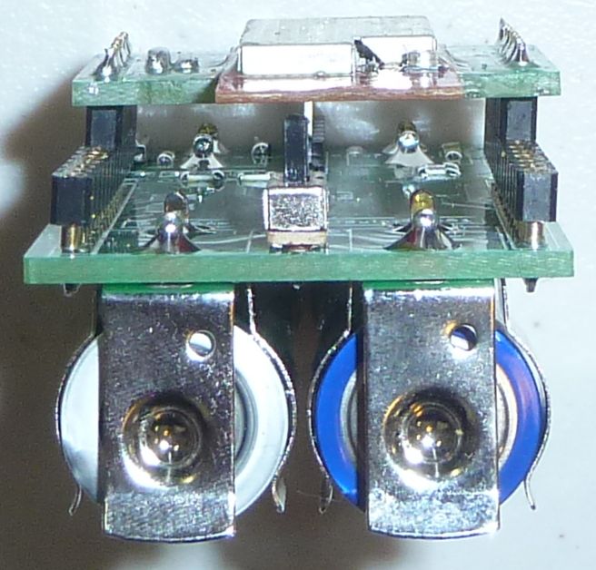
As you can see, I wouldn't want the batteries to be any closer together than they already are, or they would likely short out between them. As it stands, they're firmly in place, so no worries for now. These kinds of placement tolerance issues are hard to vet in advance prior to building a prototype. The keystone datasheet gave no guidance at all on side by side positioning. If I were to do it over, I think I'd give it another millimeter or two of safety factor separation.Of bigger concern is the switch placement. A side mounted switch might be too tight a fit because of the battery connectors. On the other hand, the existing vertical switch can potentially can get in the way of things, so I may try mounting it upside down on the battery side. This would make it less accessible than it currently is, but, at the same time, it wouldn't get bumped by accident either. I reckon that with the aid of an insulated paperclip, or maybe a chop-stick, it should be possible to turn it on-off even in the more cramped position. Probably a more correct solution would be a surface mounted side-switch that's tiny but somehow good enough to carry 600ma+ currents. Finding such a thing may take some searching though, assuming it exists at all.
In a perfect world, the radio module, if it were to use its trace antenna, would be hanging over the end of the base PCB below. Part of the reason it wasn't was out of concern as to whether the breakout board might collide with the switch. Well, with the new switch position, that won't be a worry, so if I create a new version of the breakout board for the radio module, I'd make it so that the radio module has its trace antenna hang out over the end of not just the breakout adapter, but the end of the test platform as well.
I normally use regular headers, but out of an interest in making the whole thing more compact, and for snugger connections, I made a last minute decision to use machine pin headers instead. This was after the board had already been fab'd to use regular headers. If I were to do it over, I would have bigger diameter through-holes drilled into the PCB in order to seat the machine pin female headers properly. I'll do that in the next version I get fab'd, assuming there is a next version.
At the opposite end there's space to add a pico-blade for the FTDI attachment. If that works, then in a future design there will be space for extending a few more pins out from the MCU, making for a more complete universal test platform. For present testing purposes, though, things are good enough as they are.
If anyone reading this has any further thoughts or suggestions, please feel free to jump in and post them. I find it's less fun to do everything single handedly.
@NeverDie said in Anyone using/tried the E28-2G4M27S 2.4Ghz LoRa SX1280 27dB module?:
As you can see, I wouldn't want the batteries to be any closer together than they already are, or they would likely short out between them. As it stands, they're firmly in place, so no worries for now. These kinds of placement tolerance issues are hard to vet in advance prior to building a prototype. The keystone datasheet gave no guidance at all on side by side positioning. If I were to do it over, I think I'd give it another millimeter or two of safety factor separation.
Add some Kapton tape to the sides of the terminals next to each other to insulate against accidents without making it more cramped.
-
I just now added schematics to the openhardware.io projects that I posted above.
I'm trying to post the KiCAD archive, which would be ideal, but the present system extracts the .zip file and only posts a fraction of the files in the KiCAD archive. If I find some another way that works, I'll post it then.
-
The SX1280 has three possible DIO pins, but, as implied by the library header file, I left two of them disconnected. In hindsight, I wouldn't recommend that. It turns out you can connect any of those DIO pins to any of 16 different SX1280 interrupts using an onchip switching fabric, which I foresee will be quite handy to, for example, rapidly know precisely when a CAD cycle completes or if anything was detected during a CAD cycle. Therefore, until version 2 of the adapter board, I may bodge DIO2 and DIO3 to some of the unused atmega328p interrupt pins as a workable stopgap measure.
-
OK, I posted the KiCAD 6 archives for both the Ebyte adapter and for the Barebones atmega328p testbed. They appear as a .rar file in the project files on openhardware.io. I'm no longer a bottleneck. Anyone can open them up and pick up exactly where I left off if they want to make changes or fork.
Inside the .rar file is a zip file. Simply import the project zip file into Kicad, and you're golden.
-
I received the Dorji parts I had ordered. They arrived very fast and very well packed. I got them on ebay, but for comparison I'm still waiting on everything else that I had ordered from aliexpress.
It turns out it took 3 days for JLCPCB to build my simple 2 layer PCB's. Either they're overwhelmed with business or understaffed. With any luck they'll ship out tomorrow, so probably another week to get here.
Meanwhile I received a Nord PPK2 Power Profiler, as I found a seller who briefly had some in stock. So, I'll be putting that to use to accurately compare current consumption of the various test builds after the PCBs eventually arrive from JLPCB. Meanwhile, I may try it out on an ESP8266 to finally get some solid current consumption numbers on how much power it takes to wake-up into ESP-NOW mode from a cold start. If it's good, then maybe so-called trigger boards will bring the ESP8266 back to life as a low power competitor. Also, I'm really curious as to how sensitive (or not) the ESP8266 2.4Ghz ESP-NOW communications will be to interference in a home environment that, at least so far, seems to have shredded 2.4Ghz LoRa. According to the labeling on the tin, they come with 25dBa power amplifiers, so I expect they'll do far better than a bog standard nRF24L01, which has a maximum of only just 0dBa transmit power. Of course, when you add in the cost of a trigger board, then total cost may (?) turn out to be a wash compared to other mcu/radio combos that don't require a trigger board. We'll see!
@NeverDie said in Anyone using/tried the E28-2G4M27S 2.4Ghz LoRa SX1280 27dB module?:
Also, I'm really curious as to how sensitive (or not) the ESP8266 2.4Ghz ESP-NOW communications will be to interference in a home environment that, at least so far, seems to have shredded 2.4Ghz LoRa.
My ESP-NOW (8266) 2.4 Ghz experience has been pretty uninterrupted that I know of. For about 3 years, I've been monitoring the water pressure of my home system. The sensor/ESP transmitter is at the water heater and the receiver is remote. To give some sense of the density of my WiFi environment: my browser scan detects 7 networks and I live in a medium-density neighborhood (about 4 homes/acre), so it is not too bad. Funny, the recharge curves of the system water pressure, after use, looks just like a capacitor voltage in a RC circuit, only much slower.
Unlike the low-power theme of this thread, my ESP’s drink as much as they need as they are always on and mains powered.
-
@Larson said in Anyone using/tried the E28-2G4M27S 2.4Ghz LoRa SX1280 27dB module?:
@NeverDie You Rock. That looks like a great testing platform... and tiny. In my 5-minute review I have two points to add that your post(s) solicit: 1. To protect the battery gap, as it is, how about a thin piece of cardboard? It appears that the offsets in the machine pin headers have a little room to slip a small zip-tie to restrain the cardboard so that it does not interfere with the test rig on top. It is easier to hack it than redesign, resubmit, repay and all that. 2. Love to join you on this venture so you are not single handed. I'm guilty of leaching and not teaching. I can't do it now (excuses) but hope to join you and help contribute.
By all means! The more the merrier!
I posted some PPK2 screenshots on another thread that I recently started: https://forum.mysensors.org/topic/11954/most-reliable-best-radio
It does a nice job of measuring milliamps. I wouldn't say the PPK2 is good at measuring <1ua currents though, such as sleep currents. If that matters to you, you'll want a Current Ranger, or TinyCurrents or similar.
@NeverDie said in Anyone using/tried the E28-2G4M27S 2.4Ghz LoRa SX1280 27dB module?:
It does a nice job of measuring milliamps. I wouldn't say the PPK2 is good at measuring <1ua currents though, such as sleep currents. If that matters to you, you'll want a Current Ranger, or TinyCurrents or similar.
Out of gratitude I'd like to buy a TinyCurrent for you. Saw the Donate button on the openhardware.io. Does that go to you?
The TinyCurrents device would be interesting to own. But if the granularity of the PPKII (still on backorder) is down to 1uA, then anything more exceeds my practical interest. For my hypothetical 2000mAhr battery, a burn rate of 1uA would last 228 years... again, if I did the math right. That exceeds my interest, though it is fun to chase down the details.
Been re-reading this thread for days. I want to help and hope to, if I can keep up with the blog entries. I've got a shopping list running - some of it already ordered!
-
@NeverDie said in Anyone using/tried the E28-2G4M27S 2.4Ghz LoRa SX1280 27dB module?:
It does a nice job of measuring milliamps. I wouldn't say the PPK2 is good at measuring <1ua currents though, such as sleep currents. If that matters to you, you'll want a Current Ranger, or TinyCurrents or similar.
Out of gratitude I'd like to buy a TinyCurrent for you. Saw the Donate button on the openhardware.io. Does that go to you?
The TinyCurrents device would be interesting to own. But if the granularity of the PPKII (still on backorder) is down to 1uA, then anything more exceeds my practical interest. For my hypothetical 2000mAhr battery, a burn rate of 1uA would last 228 years... again, if I did the math right. That exceeds my interest, though it is fun to chase down the details.
Been re-reading this thread for days. I want to help and hope to, if I can keep up with the blog entries. I've got a shopping list running - some of it already ordered!
@Larson That's very generous of you, but by no means feel obligated. The TinyCurrent-R would be the one to get. Same price as the TinyCurrent, but it has the BNC connector facing the correct direction for connecting directly to an oscilloscope's input terminal.
I do this stuff because it's both challenging and fun. I enjoy the precision of it. I just keep chipping away at it and eventually make progress. If my posts are of any use to others, then all the better: it all works best when everyone helps everybody else, because collectively we know more than any one of us individually. We've barely scratched the surface of what can be done. Synchronizing clocks among all the different motes and doing time division multiplexing among them would offer ultimate efficiency I think. The technology to do that is already known but the details of how to do it are not on display in a manner that's widely accessible.
-
@Larson That's very generous of you, but by no means feel obligated. The TinyCurrent-R would be the one to get. Same price as the TinyCurrent, but it has the BNC connector facing the correct direction for connecting directly to an oscilloscope's input terminal.
I do this stuff because it's both challenging and fun. I enjoy the precision of it. I just keep chipping away at it and eventually make progress. If my posts are of any use to others, then all the better: it all works best when everyone helps everybody else, because collectively we know more than any one of us individually. We've barely scratched the surface of what can be done. Synchronizing clocks among all the different motes and doing time division multiplexing among them would offer ultimate efficiency I think. The technology to do that is already known but the details of how to do it are not on display in a manner that's widely accessible.
@NeverDie said in Anyone using/tried the E28-2G4M27S 2.4Ghz LoRa SX1280 27dB module?:
We've barely scratched the surface of what can be done.
Openhardware.io gift coming. Please use it to replace your missing uCurrentGold with the proceeds. Someday I’ll contribute my own projects to these splendid forums, I hope.
-
@NeverDie said in Anyone using/tried the E28-2G4M27S 2.4Ghz LoRa SX1280 27dB module?:
We've barely scratched the surface of what can be done.
Openhardware.io gift coming. Please use it to replace your missing uCurrentGold with the proceeds. Someday I’ll contribute my own projects to these splendid forums, I hope.
@Larson Thanks! I purchased it off Ebay, which says I should receive it by July 15,
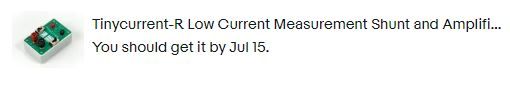
though my guess would be probably sooner than that. I'll post a picture after it arrives.
In combination with an o-scope, It should be good for those occasions where there's a need to capture very fast action in fine detail. :-) -
@Larson Thanks! I purchased it off Ebay, which says I should receive it by July 15,
though my guess would be probably sooner than that. I'll post a picture after it arrives.
In combination with an o-scope, It should be good for those occasions where there's a need to capture very fast action in fine detail. :-) -
@NeverDie Super. It will be fun to see what you do with it. Glad you have the OC scope to leverage the tool. Cheers.
@Larson You're doing the right thing by getting the PPK2. It will do 99% of what you want, and much more easily than an oscilloscope.
By the way, in case anyone is interested, there are a couple of reasons why a direct-to-oscilloscope connection beats hooking a typical 1X/10X oscilloscope probe up to, say, a uCurrent Gold or TinyCurrent. The first is that, obviously, there's less noise involved because of the short connection. The second reason is far less obvious, though, which is that the typical 1X/10X oscilloscope probes make for fairly lousy 1X connnections. For measuring small voltages on a 1X connection, you're better off using regular coax or, better still, a direct connection and eliminate the coax altogether. Why? Well, the TL;DR is that oscilloscope probes are optimized for use as 10X (which really meas divide by 10), as explained in the EEVLOG video:
https://www.youtube.com/watch?v=OiAmER1OJh4
Meanwhile.... I've been trying to get Channel Activity Detection to work on the SX1280, but so far no joy. In some sense it's its own mode, because it "supposedly" times out automatically and returns to Idle mode after a fixed number of symbol periods that's set by SetCadParams. So, I'm puzzled as to what's going on and will have to take a deeper dive to figure this one out. Unfortunately, the library does not support CAD, so there's no working example to start from. There have been some alternative libraries posted on github, so I'll see if they shed any light on how to get CAD working.
-
Well, this is a good example of how having a PPK2 helps to troubleshoot the CAD problem. We can see from the PPK2 that the CAD actually is activated, once per second, as per my code:
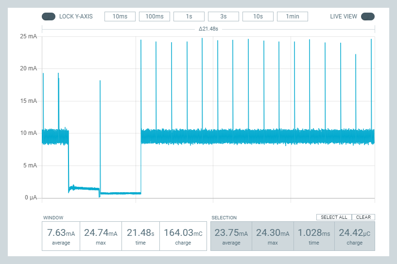
So, just knowing that narrows down the problem considerably. The problem now is no longer that but instead why it isn't setting the IRQ flag to indicate that it has finished its detection cycle? The Rx completion flags aren't being set either. -
@NeverDie Super. It will be fun to see what you do with it. Glad you have the OC scope to leverage the tool. Cheers.
-
@Larson You'll want to add some jumpers to your BOM if you don't already have them:
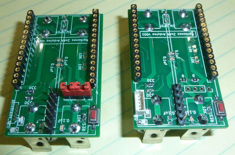
The above are two motes. The one on the left is used for measurement, and the one on the right isn't.@NeverDie Super, thanks for pointing out the jumpers - very clear to see how they would be used.
For a long time, I've wanted to make ESP programmer boards that would use springs to temporarily hold the ESP. I actually built one using pogo-pins and a 3-D printed housing pocket. It worked but was fiddly. I may try again on your radio carrier board but differently this time. I’d like to use stiff carbon steel music wire that would be mounted in drilled holes in the existing pads and create new pads on the back-side for mechanical-solder support. Some trace revision would be in order on the back-side, and Captain Tape could cover the new solder pads if needed. Think of it as a bed of nails. Carbon steel music wire is used in springs, I think, and that is what I'd like to use for its stiffness. Perhaps I’ll make the dimension between the rows of holes about 1 mm shy of the distance between the castellated indents. Then to use, push the SX1282 down into the field of springs getting 4 or 5 mm from the carrier board or until the springs start to splay out. If it works, the castellated indent would snuggly fit the wire if I can select the right gauge. One board could then serve different radios of the same class with the same pinouts. The downside may be that I have 16 new unintended antennae. Maybe I could trim these springs shorter after learning how it works.
The compelling reason for this is to preserve the radio for later permanent installation elsewhere, if needed. There may be some performance degradation as the effective trace length would be longer. I have no idea of the electrical properties of this wire. I'll find out. I’ve got too many ESP’s that are permanently attached to dead testing, or otherwise abandonded, boards. What do you think of the idea?
Atmega328P selection question: is this linked choice the right pin configuration for the footprint you used? There are so many other choices. Digikey is out of stock, but I'm presuming I'll find them elsewhere.
-
@NeverDie Super, thanks for pointing out the jumpers - very clear to see how they would be used.
For a long time, I've wanted to make ESP programmer boards that would use springs to temporarily hold the ESP. I actually built one using pogo-pins and a 3-D printed housing pocket. It worked but was fiddly. I may try again on your radio carrier board but differently this time. I’d like to use stiff carbon steel music wire that would be mounted in drilled holes in the existing pads and create new pads on the back-side for mechanical-solder support. Some trace revision would be in order on the back-side, and Captain Tape could cover the new solder pads if needed. Think of it as a bed of nails. Carbon steel music wire is used in springs, I think, and that is what I'd like to use for its stiffness. Perhaps I’ll make the dimension between the rows of holes about 1 mm shy of the distance between the castellated indents. Then to use, push the SX1282 down into the field of springs getting 4 or 5 mm from the carrier board or until the springs start to splay out. If it works, the castellated indent would snuggly fit the wire if I can select the right gauge. One board could then serve different radios of the same class with the same pinouts. The downside may be that I have 16 new unintended antennae. Maybe I could trim these springs shorter after learning how it works.
The compelling reason for this is to preserve the radio for later permanent installation elsewhere, if needed. There may be some performance degradation as the effective trace length would be longer. I have no idea of the electrical properties of this wire. I'll find out. I’ve got too many ESP’s that are permanently attached to dead testing, or otherwise abandonded, boards. What do you think of the idea?
Atmega328P selection question: is this linked choice the right pin configuration for the footprint you used? There are so many other choices. Digikey is out of stock, but I'm presuming I'll find them elsewhere.
@Larson AFAIK, any atmega328p with a 32TQFP package should work. Yes, they are in surprisingly short supply right now. Because of that, some people (like Great Scott!) have taken to desoldering them from Pro Mini's, which aren't cheaper but are easier to find. If you go that route, I recommend you buy some ChipQuik to make your desoldering a whole lot easier: https://www.amazon.com/gp/product/B0019UZP7I/ref=ppx_yo_dt_b_search_asin_title?ie=UTF8&psc=1 But that's me. Maybe you have your own preferred method. Whatever works. If you have old projects you no longer use, now is a good time to recycle their parts.
-
@NeverDie Super, thanks for pointing out the jumpers - very clear to see how they would be used.
For a long time, I've wanted to make ESP programmer boards that would use springs to temporarily hold the ESP. I actually built one using pogo-pins and a 3-D printed housing pocket. It worked but was fiddly. I may try again on your radio carrier board but differently this time. I’d like to use stiff carbon steel music wire that would be mounted in drilled holes in the existing pads and create new pads on the back-side for mechanical-solder support. Some trace revision would be in order on the back-side, and Captain Tape could cover the new solder pads if needed. Think of it as a bed of nails. Carbon steel music wire is used in springs, I think, and that is what I'd like to use for its stiffness. Perhaps I’ll make the dimension between the rows of holes about 1 mm shy of the distance between the castellated indents. Then to use, push the SX1282 down into the field of springs getting 4 or 5 mm from the carrier board or until the springs start to splay out. If it works, the castellated indent would snuggly fit the wire if I can select the right gauge. One board could then serve different radios of the same class with the same pinouts. The downside may be that I have 16 new unintended antennae. Maybe I could trim these springs shorter after learning how it works.
The compelling reason for this is to preserve the radio for later permanent installation elsewhere, if needed. There may be some performance degradation as the effective trace length would be longer. I have no idea of the electrical properties of this wire. I'll find out. I’ve got too many ESP’s that are permanently attached to dead testing, or otherwise abandonded, boards. What do you think of the idea?
Atmega328P selection question: is this linked choice the right pin configuration for the footprint you used? There are so many other choices. Digikey is out of stock, but I'm presuming I'll find them elsewhere.
@Larson said in Anyone using/tried the E28-2G4M27S 2.4Ghz LoRa SX1280 27dB module?:
What do you think of the idea?
I think it would be easier and less iffy to simply solder it on as per usual and then use ChipQuik if you later wanted to desolder it and move it to another board. But again, that's me. That said, I somewhere have one of those springy jigs that I bought on aliexpress for programming virgin ESP8266's, and it seems to work fine--well, at least for the purpose of installing bootloaders. I never tried to do wifi with them in such a jig, so I don't know what the RF consequencies might be, if any. If you can tolerate some impairment, maybe it's good enough.
Hello! It looks like you're interested in this conversation, but you don't have an account yet.
Getting fed up of having to scroll through the same posts each visit? When you register for an account, you'll always come back to exactly where you were before, and choose to be notified of new replies (either via email, or push notification). You'll also be able to save bookmarks and upvote posts to show your appreciation to other community members.
With your input, this post could be even better 💗
Register Login