Most reliable "best" radio


  • @Larson said in Most reliable "best" radio:

    I shrank the frame of the board to minimize the interference with the TestPlatform neighboring pins

    Nice! How wide is that VCC trace/plane at its narrowest point now?

    If you got it from Github, are you able to send me a pull request?


  • Hero Member

    @alphaHotel said in Most reliable "best" radio:

    @NeverDie said in Most reliable "best" radio:

    Adafruit's Clue device uses the KLJ-5030, which is 5mmx5mmx3mm:
    At higher cost I notice that there also exists a KLJ-4020, which is 4mmx4mmx2mm

    Yikes! 😳 Watch out for those shipping costs. Check my math, 4mm x 4mm x 2mm x 20 pcs = 640 cubic mm = 0.640 cubic cm = 0.0391 cubic inches, from China for $72 shipping? They must weigh a ton (or a tonne). LOL! 😂

    Seriously though, good find! I think I'll keep shopping around for a better price though. 😀

    e854f6f9-86b4-4813-8a5f-ac95452a973c-image.png

    Yeah, the price is awful. I only linked it as an example. Looking a bit harder, I see they can be had for $1.53 each from a more reliable source: https://www.lcsc.com/product-detail/Buzzers_KELIKING-KLJ-4020_C556936.html The other thing to be wary regarding it is that the manufactures website says is only audible within a 0.5 to 1m range, which, if true, would be pathetically weak.
    klj_4020.png
    So, it has me thinking "close but no cigar."

    In comparison, having heard it myself, the KLJ-5030 is reasonably loud I would say.


  • Hero Member

    Looks as though FUET has some good low-priced alternative buzzers:
    fuet_buzzers.png
    It must be something about the physics of buzzers that the thinnner they get in these small packages, the quieter they are.


  • @alphaHotel said in Most reliable "best" radio:

    Nice! How wide is that VCC trace/plane at its narrowest point now?

    KiCad tells me the narrowest VCC trace is about 0.045" (1.1 mm). I think the conventional 0.5 oz. copper is the common underlayment thickness. Is it too narrow? The return path is much narrower (Pin 1 nRF24L01). Does that matter?

    @alphaHotel said in Most reliable "best" radio:

    If you got it from Github, are you able to send me a pull request?

    Yes, I think I got your version from Github. I will learn how to send a pull request. Cool, so this is how collaboration works? I'm new to this.


  • @NeverDie said in Most reliable "best" radio:

    It must be something about the physics of buzzers that the thinnner they get in these small packages, the quieter they are.

    I'm thinking of speakers of the 1970's: the drivers, midrange and tweeters would be nothing without the cabinet boxes. Does that apply here? In the 2010's these "soundbars" come into the picture. But there is still a box involved. Yes, it is probably about the physics of sonics... I'm thinking.


  • @Larson said in Most reliable "best" radio:

    Yes, I think I got your version from Github. I will learn how to send a pull request. Cool, so this is how collaboration works? I'm new to this.

    Please don't add to your personal learning curve to create a pull request. It's not that important, at all.


  • Hero Member

    @NeverDie said in Most reliable "best" radio:

    This is what I came up with for a platform that has both pluggable MCU's and pluggable radios:

    pluggable.png

    It's a bit wider than the previous test platform to give enough space between both the two AA batteries themselves and between those batteries and the pin headers. It also has a separate row of pins along the outside in case you want to have any shields that go on top. I did away with the switch entirely. Now if you want to power it off, you just remove a battery. So, doing all that renders the backplane/power-source very simple. Also, I included two mounting holes so that the whole thing can be mounted inside a project box. Yesterday I ordered this PCB along with a pluggable atmega328p MCU board and a pluggable radio board from a fab, so nothing physical to show-and-tell just yet.

    In terms of having "plugable" compute modules, I'm thinking that maybe edge connectors might be a good way to go. I say that because I've lately been looking at expansion slots for the Adafruit CLUE, which has a similar pinout to the BBC micro:bit. Even though those modules have only a little more than 20 pins to expose, some of the edge connectors on the market that are compatible with them can support as many as 80 pins! For a plugable compute module, the more pinouts the better. That way, if you need access to a lot more pins, you would simply plug the same compute module into a backplane that gives you access to a lot more pins to, for example, directly drive an LCD display instead of having to do it all (more slowly) using an SPI interface.

    Well, that's all I've learned so far. I guess in the absence of any better ideas, maybe picking one of those 80 pin edge connectors that's compatible with micro:bit would perhaps be a worthwhile experiment to build a plugable backplane around. Especially for mcu's that come with a switchable fabric that can re-assign which logical pins are assigned to which physical pins, it would perhaps open up a lot of options for exploiting much more capable MCU's while still keeping the real estate small.

    Here's an example of one of those 80 pin edge connectors that's micro:bit compatible: https://www.amazon.com/gp/product/B08HS27D51/ref=ox_sc_saved_title_3?smid=A22NPL1KB8AOV0&psc=1
    80_pin_edge_connector.jpg
    as well as a PCB showing how it is wired for a micro:bit:
    80pin_pcb.jpg
    As you can see, lots of room to grow! The downside is that it's not small. Maybe an edge connector that's half as long would work well enough (though obviously sacrifice micro:bit compatability) and still keep things small. If there were a smaller, much higher connection density connector, that would obviously be better. Maybe @Larson 's idea of using zebra strips as connectors is more practical. Not sure. I suppose in a way the little aliexpress modules, with their array of contacts on the back of their little PCB's, are a type of connector, just not a plugable/unplugable one.Anyhow, I don't have the time to pursue it further at this juncture, so those are just some notes to either future self or to anyone who might want to tackle it.


  • Hero Member

    I was thinking of trying out the nRF52805, but it turns out making the nRF5 jump now isn't much easier than it was 5 years ago when I last looked into the nRF52 series. The main improvement in the interim is that certain popular chips, like the nRF52840 are now better supported, because they are baked into things like the Adafruit CLUE and have at least some familiar Arduino support.


  • @NeverDie said in Most reliable "best" radio:

    Maybe @Larson 's idea of using zebra strips as connectors is more practical.

    I learned about zebra strips from you - thank you very much. I was unable to re-establish connections for an existing commercial products and I don't know why. My thought was that zebra strips were some technology and complex signaling that is beyond my capacity. The device is probably over 20 years old. Therefore, I would not recommend zebra strips because I don't know enough about them.

    This pic from your link is more telling of the capability of your referenced connectors. 9f5492d7-b994-4cd1-9d05-9c9769eeff88-image.png For now, I don't know why these are called edge-connectors. I thought edge-connectors were flat male blades with double-sided contacts that were fitted in sloted female gaps. The ones I think I've seen have an index slot for, I suspected, polarity protection and alignment. Maybe I've got this all wrong and they are called something else - like card connectors.


  • Hero Member

    @Larson said in Most reliable "best" radio:

    don't know why these are called edge-connectors.

    @Larson I think they're called edge connectors because they mate with the edge of a PCB.


  • @NeverDie Yes, I think we are surfing the same wave. I'm thinking of a PCB mount that will recieve a perpendicular PCB board with double sided connectors like this: https://www.ebay.com/itm/122943051785?hash=item1c9ffa1809:g:daAAAOSwd4tTxdNW

    Maybe there is an application of these for the radio modules that have the single row SMD mounting pads? One would need to ignore the opposing connectors. Better yet, maybe there are radio boards (?) that could be designed to slot in... just thinking. The NRF24’s would require double-sided 1x4 board and receivers. That would be cool and compact.

    But then there is the ground-plane to think about?


  • @NeverDie said in Most reliable "best" radio:

    CORRECTION: Earlier I said that Adafruit's TPL5110 breakout board appeared to use a 1M pulldown resistor on DONE. I remeasured today and that's wrong. It's actually a 10K resistor.

    Thanks for redirecting me to this thread. I think you were right on your original 1M Ohm assertion. Since I'm playing with my new TPL5110,s I took it on to make my own MM measurements. While my Harbor Freight MM might not be the most accurate instrument, I did show the resistance between DONE and GND to be 900 K'ish. Next, I got out the magnifying glass to spy the resistor in-line with said pins to have a marking of 1004. Google affirmed that that means 1 M ohm. So, your 5K, or 10K would be a big change – and if it comes at no cost for the quiescent current AND enables ESP action, then perfect!


  • Hero Member

    @Larson said in Most reliable "best" radio:

    @NeverDie said in Most reliable "best" radio:

    CORRECTION: Earlier I said that Adafruit's TPL5110 breakout board appeared to use a 1M pulldown resistor on DONE. I remeasured today and that's wrong. It's actually a 10K resistor.

    Thanks for redirecting me to this thread. I think you were right on your original 1M Ohm assertion. Since I'm playing with my new TPL5110,s I took it on to make my own MM measurements. While my Harbor Freight MM might not be the most accurate instrument, I did show the resistance between DONE and GND to be 900 K'ish. Next, I got out the magnifying glass to spy the resistor in-line with said pins to have a marking of 1004. Google affirmed that that means 1 M ohm. So, your 5K, or 10K would be a big change – and if it comes at no cost for the quiescent current AND enables ESP action, then perfect!

    I just now checked the adafruit schematic for the TPL5110, and you're right: it does show a 1 megaohm resistor. I guess I must have measured it wrong. https://github.com/adafruit/Adafruit-TPL5110-Power-Timer-Breakout-PCB


  • Hero Member

    @NeverDie said in Most reliable "best" radio:

    @alphaHotel said in Most reliable "best" radio:

    E01-2G4M27D

    I'm fairly certain the ones I ordered won't be arriving with antennas (as none were pictured in the aliexpress posting), but, no problem, I'll let you know for sure after they arrive. Most likely if you have an old wi-fi router that you no longer use, you could probably unscrew those antennas and use them, since they'd also be 2.4Ghz.

    @alphaHotel Reporting back: I received them, and mine did not come with any antennas.


  • @NeverDie said in Most reliable "best" radio:

    @alphaHotel Reporting back: I received them, and mine did not come with any antennas.

    That's as I expected too because of the lack of any photos in the listings. Thanks for confirming, it's good to know. I do have a handful lying around from old WiFi routers as you mentioned.


  • Hero Member

    I've had success getting the nRF24L01 to listen once per second for packets at an average current drain for just the nRF24L01 of 5.35ua. Not bad! The snag I'm running into though is that the listen window, encompassing power-up of the nRF24L01 through Rx mode is 1.6ms. However, if I use the atmega328p to time that 1.6ms, it raises the average current drain to 45ua, which is worse than my keyfinder keyfob's current drain (about 30ua on average). So....I need to find some way to sleep the atmega328p for 1.6ms in order to keep the total current drain low. However, how to do that? The TPL5111 has a minimum period of 100ms, so that's out. The atmega328p's WDT has a minimum period of 16ms, so that's out too. Unfortunately, the atmega328p has no built-in RTC. Even if I were to add an external RTC, I don't know of any that would let me dial-in 1.6ms.

    Presently I can think of only two solutions:

    1. Add some kind of external oscillator and feed it to Timer2 in asymchronous timer mode while sleeping the atmega328p. However, I can't seem to find from the datasheet what the current drain of that configuration would be, so it seems like a shot in the dark.

    2. or, possibly use a GPIO pin to charge up an external capacitor and somehow calibrate the charging time so that when the capacitor discharges via some RC time constant it triggers a falling edge interrupt on the atmega328p to wake it up from sleeping after 1.6ms (the sleep time begins after it charges the capacitor). I haven't tried this, but it might actually work. It would notionally be kinda/sorta similar to how one can use an atmega328p to charge up a capacitor in order to determine the capacitor's capacitance value: https://www.norwegiancreations.com/2019/08/using-a-simple-arduino-to-measure-capacitor-value/.

    If anyone has any other ideas on how to sleep an atmega328p for 1.6ms, please do post.

    [Edit: Regarding #1, I suppose I could try measuring the sleep current with external asynchronous mode engaged but nothing connected to it. If it's acceptably low, I could then hook up an ultra low current 32.768K external crystal at an additional 500na or so. Hopefully there's some way tot turn everything off on the atmega328p except for the asynchronous counter. I'm doubtful as to whether I can apply such fine grained control like that to one of the sleep states (POWER_SAVE MODE), but maybe....? Here's some reason to be hopeful:

    Power-save: is similar to the power-down mode, but the Timer2 is still awake and could be operated via an external clock.
    https://wolles-elektronikkiste.de/en/sleep-modes-and-power-management

    Ugh. Except Timer2 is an 8 bit counter...., but that's OK: 1.6ms would be 53 ticks on a 32.768k oscillator, so at least that part should work if the mcu sets timer2 to overflow in 53 ticks and then go to sleep and if that overflow will trigger an interrupt to subsequently wake the mcu back up after 1.6ms.

    Well, it's a plausible theory. Just need to test it!

    Is it worth the effort though? Even if it worked, an nRF52 module would outperform this type of setup, would be more compact, would be easier/faster to assemble, and would (probably) be lower cost as well. Hmmmmm..... And the nRF53 will be even better hardware still, though the nRF53 does come with the extra overhead of an RTOS....]


  • @NeverDie

    Strikethrough
    [Would 15 mseconds be close enough?
    #include <LowPower.h>
    LowPower.powerDown(0, ADC_OFF, BOD_OFF); //0 gives SLEEP_15MS,] Strikethrough

    [Edit - Sorry - on rereading is see the objective is 1.6 mS not 16 mS. I like your Timer suggestions - that is what they are for.]


  • Hero Member

    I never realized you can send/receive BLE data using an nRF24L01:
    use NRF as a BLE Module | Arduino NRF24L01 Bluetooth Low Energy Tutorial – 12:17
    — electronic GURU

    Unrelated to that,I found a nice introductory tutorial series on then nRF52:
    https://www.youtube.com/c/SumairsEmbeddedEngineering/videos

    Most of the nRF52 stuff on youtube only considers either just the hardware or just the bluetooth aspects, but this series covers much more than just that. Lately Nordic's development has embraced the Zephyr RTOS, but this youtube series does not rely on Zephyr, which may (?) be good if you want tight control over the hardware without the overhead of an RTOS.


  • Hero Member

    @alphaHotel said in Most reliable "best" radio:

    @NeverDie said in Most reliable "best" radio:

    @alphaHotel said in Most reliable "best" radio:

    @NeverDie With the first version of the battery/MCU board, you lamented running traces directly under the batteries. You have the space now to re-route them but choose not to. Did you find a way to resolve the issue it caused?

    Actually, I fixed it on the new version (pictured above). The red traces run on top, so they're adequately isolated from the battery holder metal, which is on the back side except for the through-holes where it sticks through the board. Where I ran into trouble was running traces on the back side, beneath the battery holder metal. If the battery holder metal was pressed up hard against the board, some shorts resulted on some of the boards. The workaround was to not press the battery holder metal hard up against the board, but the new version removes that concern entirely.

    Okay, I see now. I misunderstood the original issue and also didn't think about the top/bottom side orientation in relation to those traces vis-a-vis the battery holders. Thanks for clarifying.

    I received the PCB today, and I think I see now the source of your confusion: I had put the silkscreen outline for the battery and its clips on the FRONT instead of on the BACK where it belongs. I'll correct it on the next iteration. On this first iteration I'm mainly just testing for fit and to make sure the space is such that the battery clips don't short against either themselves or against the headers. I'll also be adding polarity markers as a reminder for the correct way to insert the batteries.


  • Hero Member

    Here's the first pass on the new version:
    backplane_v001.JPG

    The good news:

    • I widened the separation between the batteries, and now the clips aren't at risk of shorting against one another.

    • list itemThe machine pins now sit nice and low against the PCB. The idea is that this way a shield can arch overhead without having to add much to the overall height. That's why I have regular headers on the outside part.

    Not so great: as a guard against shorting against the clips, I maybe overcompensated by overwidening the headers as well. I think I can probably narrow the overall board width by 3 to 6mm and still have adequate clearance. I'll do some more iterations until I zero in.

    Also, unlike the earlier test platform, this board lacks a way to separate out current measurement to the radio vs to the mcu. Since I already have the test platform for that, I don't think I care, but maybe someone else would want that? It could be added to the backplane, or it could be added to the plug-in modules themselves.

    Lastly, I'm noticing that the battery clips fit so tightly against the PCB holes that you probably don't even need to solder them! 😉


  • @NeverDie said in Most reliable "best" radio:

    I widened the separation between the batteries, and now the clips aren't at risk of shorting against one another.

    It's looking good! I'm curious, how far apart are the battery clips now (center-center)? I noted on the original board layout it was 15.62mm. I'm guessing it's about an extra 3mm based on the lines of the silkscreen and the size of the mounting holes you added.

    ff86fd60-4de9-4129-aad3-08bf203766fc-image.png

    Also, an off-topic question for you - I believe I read in a thread somewhere recently (not sure which one though) that when adding a USB port you prefer USB Mini. Which footprint do you like to use and where do you source them from?


  • Hero Member

    @alphaHotel said in Most reliable "best" radio:

    It's looking good! I'm curious, how far apart are the battery clips now (center-center)?

    Most likely it will be either 16.75mm or 17.75mm. 17.75mm is plenty wide. I have some test boards coming at 16.75mm to see if losing 1mm still guarantees adequate separation.

    As for which USB connector, it depends on context. If size is not an issue, then lately I'm liking USB-B more than USB-mini. It's the same USB connector commonly found on the classic Arduino Uno. Super robust. I recently sourced 10 of them from mouser: https://www.mouser.com/ProductDetail/490-UJ2-BH-2-TH at close to 50 cents each.


  • @NeverDie, Thank you.


  • Hero Member

    @alphaHotel The 17.75mm separation is as close as they can get and still use an M3 on the mounting holes. For the 16.75mm boards I have on order, I reduced the mounting holes to M2 sizing.

    The long turnaround time when ordering PCB's is a frustration. I should get my cheap CNC PCB etching machine up and working again to resolve these silly dimensioning issues without having to send off to a fab somewhere.


  • @NeverDie I thought your turnaround time was decent compared to mine. It has been taking up to 3 weeks for me to get mine from OSHpark. The last fab I ordered, I priced it out at PCBway but they were $29 versus OSHpark's $16. I do find though that within days of sending it off for fabrication, I'm making improvements to the design and kicking myself for placing the order too soon.


  • @alphaHotel said in Most reliable "best" radio:

    I thought your turnaround time was decent compared to mine.

    My latest OSH Park order was 9 days inclusive (ordered 6/20/22, delivered on 6/28/22). I find that pretty remarkable. I've read, somewhere, that the timing is at risk of your position in the panel queue; if you are early on the panel, then it is slower. There is a “super swift” service from OSH for a charge. Free-shipping moves faster than I can, so I can wait. The price can't be beat and the quality is great (except for the errors that I make!!!)

    @NeverDie
    The silkscreen markings for the AA mount posts on your Test Platform V001 are on the right side for me. Mine arrived last week! Sure, the markings are on the reverse side, but once the batteries are installed, that side is invisible. I’m still fretting the moment when I need to solder the Atmega 328P chip.

    To follow-up on earlier posts: the speed of delivery from China has dramatically improved. Most of the orders I’ve place in early June have arrived. Even the hard-to-get Atmega 328P chips have arrived so I don’t have to desolder my old Nano’s or ProMini’s. And the Chinese packaging is efficient - less trash for my conscience. Digi-Key leaves me wondering how such little can arrive in a box that is so big. But... Digi-Key is so fast.


  • Hero Member

    I'm finding that some of the basic UART example programs in Segger Embedded System's IDE no longer even compile for the nRF52-DK without encountering obscure errors that, judging from some youtube videos, didn't exist a year ago. Did Segger fail to maintain their example code during covid? I couldn't get to the bottom of it, so I'm punting on SES and will be switching to gcc, which I hope won't have the same issues. Fingers crossed.

    Looks as though I'll be sticking with SES a bit longer, because it does contain at least one example shell for the nRF52805, and as long as I can hollow out and fill that shell with bare metal code, then (so far) it all seems to compile and upload and the code works on the nRF52805. At the moment I've confirmed that the bare metal UART code I put together from just the datasheet alone (which has far more ambiguity in it than I remember it having) is now properly working inside the nRF52805, which was (is?) probably the hardest thing to get going, but now that it's in place (for debugging purposes) I feel more comfortable moving ahead like this. One thing I do like about SES is that compared to GCC the compile and upload cycle happens very, very quickly. That alone may not by itself be a deciding factor in what to toolchain to choose, but it is a nice luxury that I truly enjoy.

    Next up: getting some bare metal proprietary radio code to work on the nRF52805. Ignoring the PCB antenna, the rest of the module looks as though it is smaller than the size of a dime! I don't yet fully grasp the details of how Nordic crippled it, so I hope I won't be tripping across any nasty gotcha's. 😉 Apparently one of the benefits of the crippling it is that it is more power efficient (as, for instance, it has less memory to retain while sleeping). Compared to its siblings, it has "only" 24KB of RAM and 192K of flash, but that is nonetheless hugely more than what the atmega328p has, so from that perspective it should have more than enough for doing most Arduino-type things. It's biggest cramping limitation seems to be its very small number of GPIO pins (technically 10 pins, but really more like 9 pins since one of the ten pins serves as a RESET pin).


  • Hero Member

    I have nRF52805's and nRF52832's talking to one another using the proprietary radio, and I obviously have nRF2401's talking to one another, but getting the two groups to talk to each other? It's not obvious how to do that: Enhanced Shockburst of the nRF24L01 has a weird 9 bit section called PCN in the middle of it, and it's not clear how to get an nRF2 to receive that kind of oddball frame without rejecting it. That said, I think it probably can be done, but it would maybe turn into a long detour that I'd rather not take right now. It turns out there does still exist regular, non-enhanced Shockburst which the nRF24L01 can still use and which doesn't have the oddball 9-bit PCN, but then the maximum transmit speed of an nRF24L01 is limited to 1mbps. That's no good, because I want to use the faster 2mbps, which is almost the entire allure of using Nordic chips instead of something else. So, in the interest of not getting detoured, when it comes to 2.4Ghz, I guess I'll just plow ahead using just nRF52 chips and see how low I can drive the energy consumption on an nRF52805 and still be able to wake it up with a radio packet. Since a lot of the energy goes toward just waking up the radio and getting it up to speed before it can receive anything, it may yet turn out that accepting a 1mbps on-air bitrate won't be too big a compromise, but I'd rather make that decision based on actual measurements rather than guesswork alone.

    Between now and then I need to confirm that the BC805M has functioning DCDC circuitry in it, and I also need to measure the sleep current on the BC805M to make sure it won't be worse than expected with the integrated RTC running, which I'd like to use instead of a TPL5111 if the current drain will allow. If I need little to no external circuitry, then, aside from batteries, this whole thing could literally fit on a dime.

    By the way, and unrelated to all that I just wrote, I finally came across a nice articulate introduction to the stm32 and its toolchain:

    #1 Say NO to ARDUINO! New ARM Microcontroller Programming and Circuit Building Series – 12:02
    — BuildYourCNC

    He had already done one introductory series, but now he's re-doing it to make it current and more polished. So far I like his approach of starting with the simplest possible thing and then building up from there. STM has some pretty cool looking tools that I haven't seen before in other toolchains. For instance, one of the tools has Node Red built right into it! In addition to that, there's a debugging tool that not only allows you to inspect the value of a variable, but plot its value over time. Like I said, nifty cool stuff. That said, the whole thing looks like a surprisingly PITA to install, which is where this video series comes to the rescue by holding your hand through all that. If you ask me, STM should add this guy to their payroll, because he clearly "get's it" far more than the ST product managers do. For instance, he shows that if you follow the ST installation instructions to a T, then you run into dead links that have evidently gone stale. So, he walks you through what the instructions should have been to avoid that.


  • @NeverDie Just checking in. I've received lots of different radios and built two of your bare-bones kits. Soldering the Atmega328P chips were easier than I thought – first time ever on pins that small. My MM showed many, many solder bridges existed. Solder-wick helped fix that. Hope I didn’t burn the chip.

    Before I start running tests on the different radio’s as you have, I’ve been getting a GPS functioning which has been fun. After collecting data around the perimeter of our small property, I figured out how to do a XYZ 3-D plot in Excel – not easy.

    In the GPS process I’ve been watching this video (https://www.youtube.com/watch?v=gtM832Z0ujE&t=219s ) and he has a conclusion that you might be interested in: locating the transmitting radio (nrf24L01) close to the MCU was limiting the packet/per/second performance, and limiting range. With this in mind, I hope to test your radio carrier boards on a Dupont wire extension raising it off the bare-bones board. Then test with and without and see how it does. Again, I’m hoping all that wire doesn’t inadvertently create unwanted antennae interference.

    But, obviously, I’m on the slow road still.


  • Hero Member

    @Larson said in Most reliable "best" radio:

    @NeverDie Just checking in. I've received lots of different radios and built two of your bare-bones kits. Soldering the Atmega328P chips were easier than I thought – first time ever on pins that small. My MM showed many, many solder bridges existed. Solder-wick helped fix that. Hope I didn’t burn the chip.

    When I encounter hard-to-rid solder bridges, I ladle on gobs of that resin that I linked for you earlier on amazon. Use tons of the stuff, such that the whole area is submerged in it. Then when you hit the area with a hot soldering iron, the solder bridges all magically separate like Moses parting the Red Sea. Not all resins are equally effective in that regard, which is why I pointed you to a resin that seems to work really well. There are also some "hoof" soldering tips that help pull off excess solder onto the tip via capillary action, which you can then wipe off onto brass wool or a sponge. Those tips are a definite nice-to-have, but not strictly necessary. With the right resin, the resin will do most of the work for you. If you're still having trouble, then you may want to raise the heat on your soldering iron. When I want to deliberately create solder bridges, I lower the temperature on my soldering iron to make it closer to the melting point.


  • Hero Member

    I'm using my "proto-board" to prototype a basic nRF52805:
    alt text
    It's working fine, except for the reset pin. Apparently Nordic has introduced new "advanced protection" that's preventing me from assigning and enabling P0.21 to be the RESET without some sort of complicated obscure sequence to disable the advanced protection.


  • @NeverDie Thanks for the tip. I went as far as dipping my solder wick in my new SRA Flus #135 (yes, your recommendation; thank you again). That may have been the trick because ... it worked! Actually, I didn’t dip it but smooged the stuff onto the wick using a toothpick as a trowel. Yea, it was a mess afterwards. I used a foil tray as an alcohol bath before cleaning with a toothbrush.

    My problem today is bootloading the brand new 328's with my old USBASP. The IDE says something about “cannot set SCK period” and then “initialization failed”. I’ve been here before and it just takes time to relearn. I made ReadMe notes but I can’t find them. I’ll try again tomorrow.


  • Hero Member

    @Larson I use an AVR Dragon. I don't think they are even manufactured anymore, but it still works and it makes burning bootloaders and setting fuses a snap from within what is now called Microchip Studio (what used to be called Atmel studio). It's also a "high voltage" programmer to resurrect chips that low voltage programmers cannot. It turns out I've never had a reason to use the high voltage feature, but it was a selling point at the time.

    Anyhow, I meantion it because if you can find a programmer that does dance with Microchip Studio, it's a fairly easy interface to learn and to use. You just go to menu Tools....Device Programming... and it's all right there. Microchip Studio is free so if you want to preview what it might look like, just download it and give it a squiz. I don't actually use Microchip Studio for anything other than just this particular feature


  • @NeverDie said in Most reliable "best" radio:

    Anyhow, I meantion it because if you can find a programmer that does dance with Microchip Studio, it's a fairly easy interface to learn and to use. You just go to menu Tools....Device Programming... and it's all right there. Microchip Studio is free so if you want to preview what it might look like, just download it and give it a squiz. I don't actually use Microchip Studio for anything other than just this particular feature

    Thanks for another tip/reminder. I still have the Atmel Studio 7, Microchip Studio predecessor, loaded and I think that played a role for me in the past in this hurdle – you reminded me of that. I’ll give it another go. I remember the strength of AS7 was that one could debug code (see registers) a command at a time – pretty cool.


  • @Larson said in Most reliable "best" radio:

    My problem today is bootloading the brand new 328's with my old USBASP. The IDE says something about “cannot set SCK period” and then “initialization failed”.

    If you have a second USBASP or an Arduino of some sore lying around, you could try to update the firmware on the USBASP. I recommend this edition, latest release and a Google search for "how to update usbasp firmware". You may see that with release v1.06 of that repository, there was an improvement that "Includes automatic SCK slowing".

    Of course, the problem may be more rudimentary. Can you read the fuses? Are they set to use an external oscillator that doesn't exist?


  • @alphaHotel I'll try the firmware update. Thanks. I suspect my problem is the SCK speed. I get immediate failure. I don't think I can reach the fuses if the 'target' chip doesn't have a bootloader. Do I have that wrong? The wierd thing is that I used my USBasp to bootload an extra Nano I have on hand. That worked fine. On the bare bones board, I've double/triple checked the connections and I've rechecked the 328 chip for solder bridges & solid connections with pins. I have downloaded your recommended link. The 2011-05-28 Thomas Fischl Readme.txt file looks complicated. I'll see if I can manage that. Thanks again.


  • Hero Member

    BTW, I had previously failed to notice that an nRF52840 can be powered from up to 5.5v because it has a built-in buck regulator designed to manage that higher input voltage. That might make a 3 or possibly even 4 battery configuration, depending on battery chemistry, pretty compelling, because it would extend battery life so much longer.


  • @alphaHotel Still working on getting my USBASP reprogrammed. After googling I found this site: https://www.electronics-lab.com/project/usbasp-firmware-update-guide. That program says to create a new programmer; I used a Nano and uploaded the ArduinoISP successfully. Next I combine the avrdude.conf, avrdude.exe, and the update hex file in one file as suggested. I used your latest release link to find the update hex file to be main.hex for the Atmega8 that lives on my USBASP. The readme files in your link lead me to that conclusion.
    After connecting everything together I enter “avrdude -C avrdude.conf -P COM9 -p m8 -c avrisp -b 19200 -U flash:w:usbasp.atmega8.main.hex:I” in the windows command line.

    I get these errors:
    avrdude: error at avrdude.conf:1133: programmer type jtagice3_updi not found
    avrdude: error reading system wide configuration file "avrdude.conf"

    I found jtagice3 in the config file to be a defined programmer. I feel that I’m close. Any ideas? I continue to work on it.


  • @Larson said in Most reliable "best" radio:

    I don't think I can reach the fuses if the 'target' chip doesn't have a bootloader. Do I have that wrong?

    You can reach (read/write) the fuses with a USBASP regardless of whether there is a bootloader. If you have any troubles, shoot me a message in the chat or start a new thread somewhere and I'll help you through it.


  • @alphaHotel Chat sent. My apologies to NeverDie for the distractions to a very fine thread.


  • Hero Member

    @Larson No worries. I'm glad you're finding the help you need.


  • Hero Member

    Reporting back on Piezo buzzers discussed earlier in this thread: I just now tested out a ceramic disk piezo, and, indeed, it appears they more or less require a resonate cavity of some kind to get loud enough. Putting a 3.8KHz square wave into one that already has a resonate cavity to go with it, it appears to consume about 400ua at 3v and around 260ua at 1.8v. Interestingly, it appears you can identify the frequency of maximum loudness by selecting a frequency that gives rise to the maximum current draw. A steady tone sounds like a hearing test though, so for a more pleasant effect, I guess you have to dial-in some creative frequencies.

    Anyhow, despite the cheap price for ceramic disks, I don't feel like designing a suitable resonate cavity for one, so I guess I'll look more into the premade surface mount buzzers that have resonate cavities already built into their modules.

    I had thought that I wouldn't need a particularly loud buzzer, and maybe that's still the case, but since I will be putting these into sealed plastic boxes as a locator beacon, I guess maybe the louder the better in terms of finding it by ear. The trade-off is that louder mostly seems to also mean bigger.

    The premade buzzers fall into two camps: actively driven by some kind of built-in circuit vs. externally driven. Since the above initial test appears to indicate that current drain won't be much, I'm leaning toward driving it "externally" with an MCU pin so that I can make R2D2 sounds if I want to. Well, I'm joking about R2D2, but I would much prefer something that doesn't sound like a hearing test.

    BTW, I had thought that changing the duty cycle on the square wave used to drive the piezo would change the volume, but in the tests I performed so far, the duty cycle length actually seems to have almost no effect.


  • Hero Member

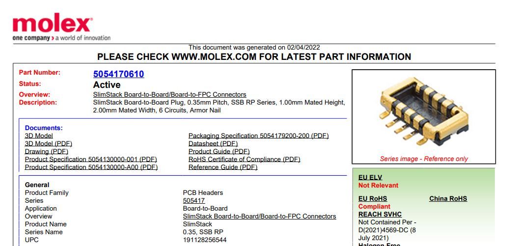
    Reporting back: I finally found a name for some "press-fit" board-to-board connects: Molex slimstack.

    For instance, it could maybe be used for connecting a "compute module" to a backplane. Pitch is just 0.35mm, and they come in all sizes from 6 pins up to 60 pins:
    slimstack.JPG

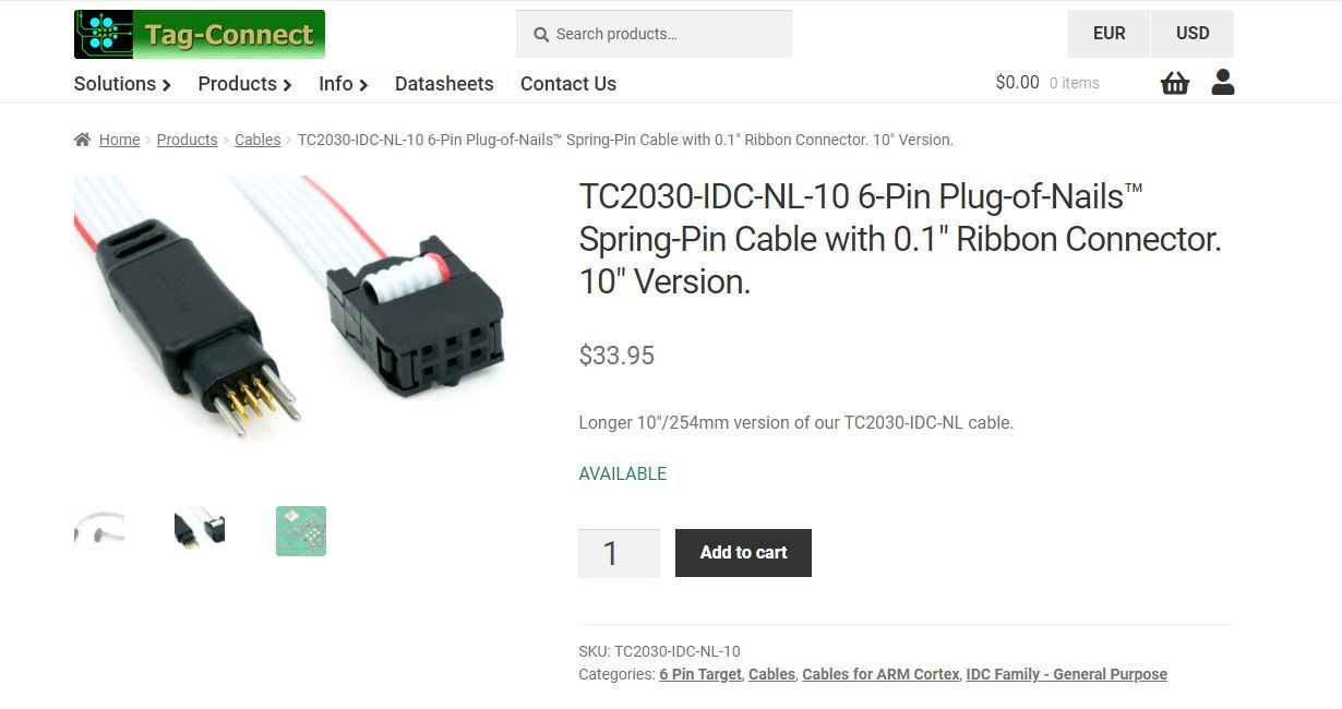
    On the other hand, for a temporary programming connection, the 6 pin tag-connect might be a good idea:
    tag-connect-6-pin.JPG

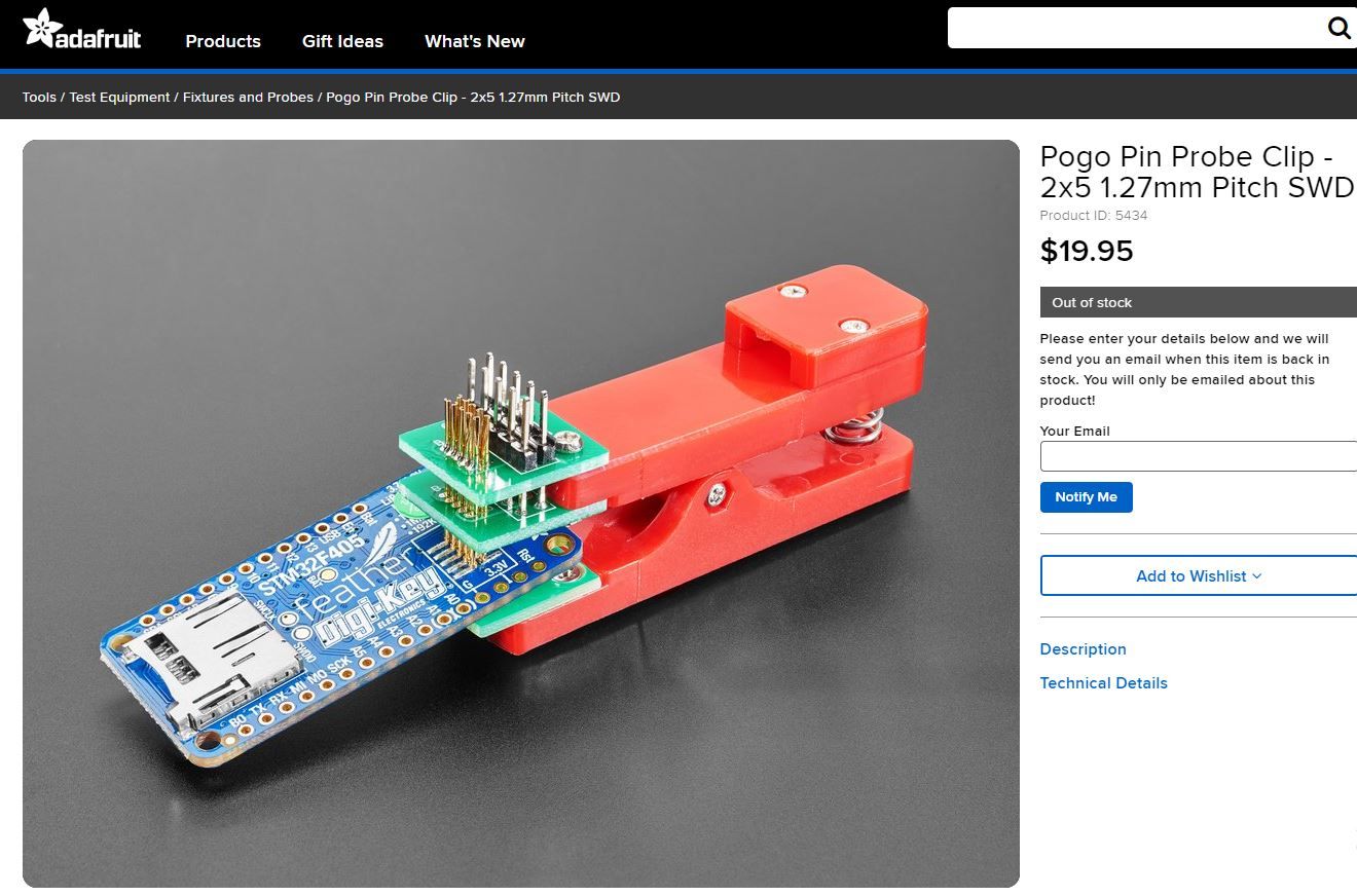
    Or you could possibly use a pogo-pin clip:
    pogo-pin-clip.JPG

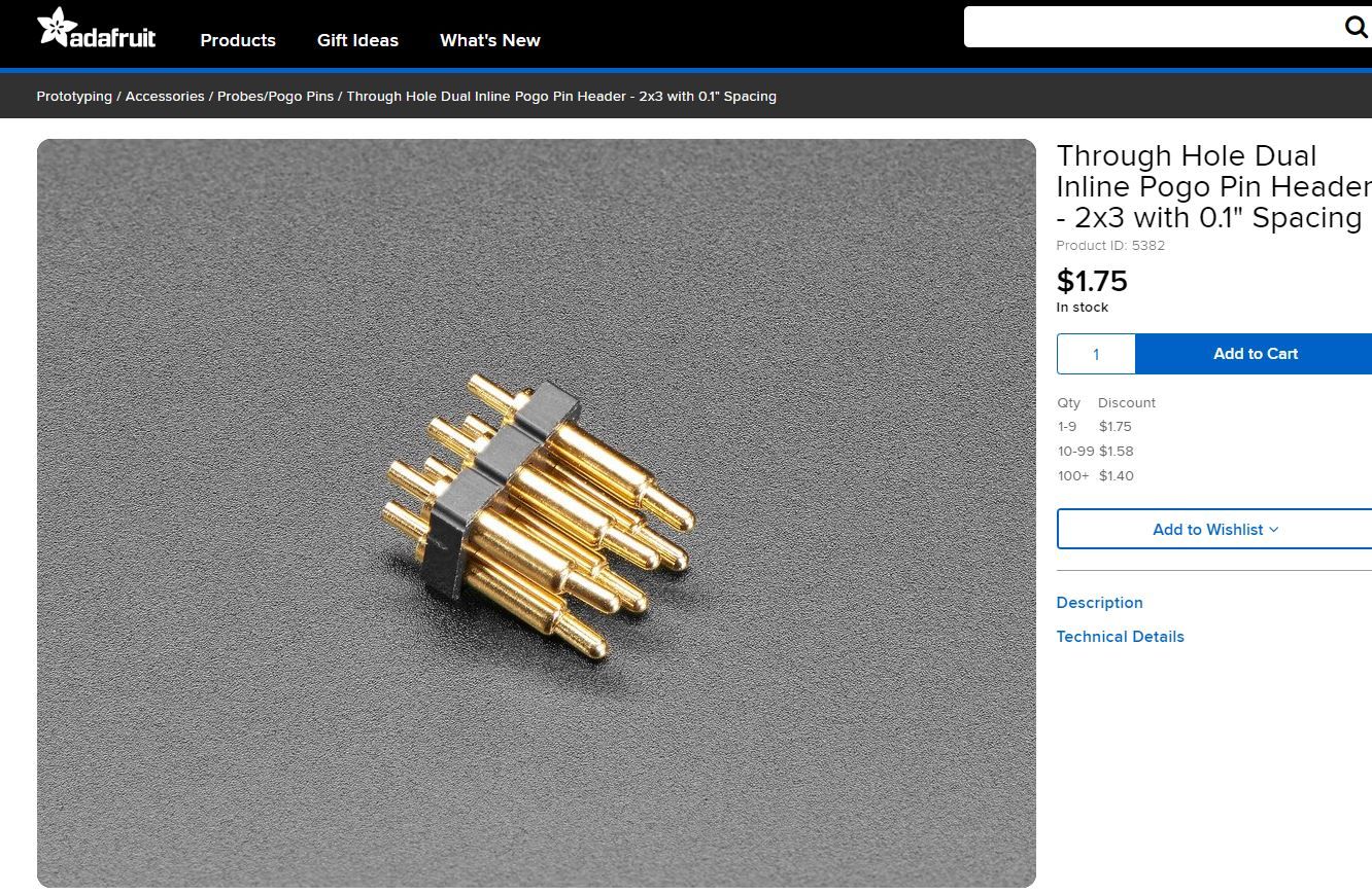
    or possibly DIY your own using an inexpensive pogo pin header:
    pogo-pin-header.JPG

    For that matter, with a few registration holes and a toggle clamp, it looks to me like you could have a darn good connection for either one-off programming or for more extended debugging:

    toggle-clamp.JPG
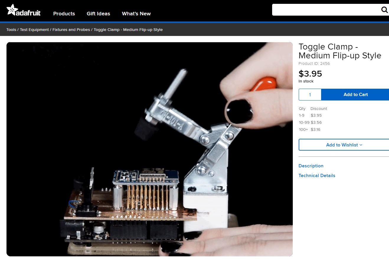
    I think I may move in that direction, because then you can spread out your pogo pin pads and fit them wherever there's extra a little extra space on your PCB rather than having to bunch them all together, as in the case of the other solutions. In that sense, I suppose it's more or less a conventional custom-built bed-of-nails.


  • @NeverDie said in Most reliable "best" radio:

    I suppose it's more or less a conventional custom-built bed-of-nails.

    😂 😎


  • Hero Member

    @alphaHotel

    Unfortunately, it also looks like it's the most work. I tried the picoblade on Version 1.0 of the Barebones, but I found that although picoblade makes the connection easily, the disconnection process is hard because it locks into place when you plug into it. So, for small projects, I'm looking into JST-SH connections, which have 1.0mm pitch and maybe (?) don't lock as well, which in this instance would be a good thing. I found some on amazon:
    https://www.amazon.com/dp/B01DUC1M2O?psc=1&ref=ppx_yo2ov_dt_b_product_details
    but the sockets are vertical. For right-angle sockets, I may may have to order from Aliexpress, because even Mouser just doesn't seem to stock them.

    I was faced with this same problem previously when I did this project: https://www.openhardware.io/view/510/Multi-Sensor-TempHumidityPIR-LeakMagnetLightAccel

    My "solution" at the time was, in future versions, to use a micro-usb connector, which indeed was much smaller, but there was nearly universal pushback on that from people saying that anything which looks like a micro-usb connector would be mistaken for an actual USB connector, and at some point end-users would hook it up wrongly on that assumption and basically destroy the system with 5 volts. Thinking about it now, that grim outcome could be avoided by the addition of just a single diode, but then again that's yet another extra part and more board real estate.


  • @NeverDie Jonathan Oxer a little while back went through a similar process with programming headers for ESP8266/ESP32 boards. He discusses some of the challenges and tradeoffs in his video(s).

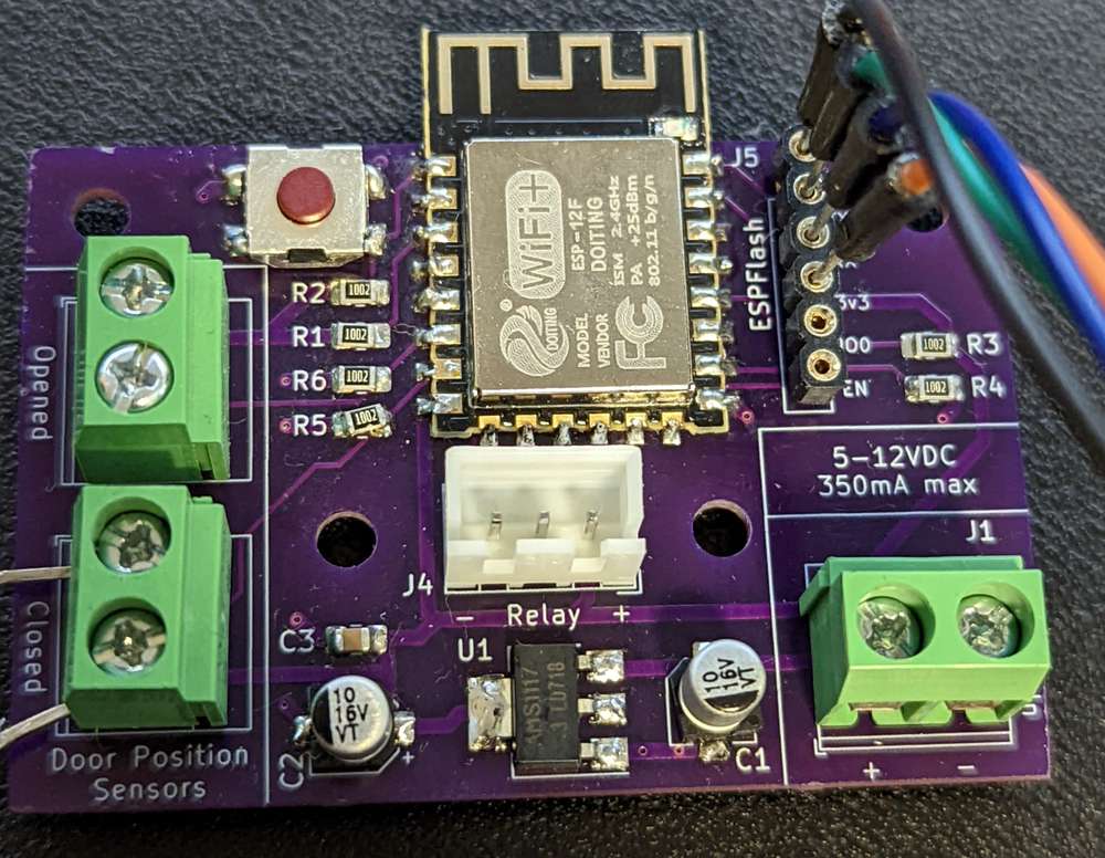
    My personal opinion on trying to shrink them down is to keep with pin headers and just make them smaller. It's easy enough to find 1.27mm pitch IDC connectors. Your JST connector idea is good too. In the end, this is mostly a target audience scenario, it seems to me. My most recent board (still working on it), employed Oxer's ESPFlash header but I kept it with a 2.54mm pitch package because I have a ~million headers with that spacing and I wasn't cramped for space. (pic below)

    If it's board-to-board as in connecting a radio module to an MCU backplane, then it's more of a use-case and dealer's choice scenario, in my mind. Those Molex SlimStack connectors look interesting.

    PXL_20220721_143556014.jpg

    I don't know if that helps or if I'm blowing smoke in the wrong direction. Just adding my voice.


  • Hero Member

    @alphaHotel Thanks for your post. It reminded me that for one-time programming, all one really needs is just the through-holes on the board. You can then bend the pins on a male header to create a kind of "weave" pattern, and that alone is enough to hold it into place during the programming, after which you can simply remove it. I've confirmed this works at 2.54mm pitch, and so I'll try it at 1.27mm pitch. I expect it should work well with that too.

    I did find this video, which makes it seem fairly straightforward to set up a custom bed of nails:
    Building a low-cost test fixture – 22:36
    — FOSDEM

    but he did say during the Q&A that it took him 4 days to design it. However, with the benefit of knowing his solution, I don't think it should take anywhere near that long to design just the PCB part of it. Maybe an hour, give or take? Someday I'm going to try it. His approach to the push-pin alignment seems quite simple and, I would think, should be easy to adapt to a whole range of different targets.


  • @NeverDie My personal preference is the Tag-Connect. It costs a bit upfront to get into it, but then there's zero ongoing BOM cost per board, and the connectors are very sturdy, so I don't get bad connections, even while doing extended troubleshooting.

    Of course, if I hadn't needed them for a customer project, I might never have sprung for the upfront cost, as the cables are somewhat spendy for the what they are. But they are very well made, and have been great for me. The board footprint is pretty tiny, so that has yet to have ever been an issue in my projects. The footprint is also keyed, so you can't put the cable on backwards. Always a good thing. Also, since the connection points are not through-holes, you still have the back and interior of the board for routing traces. Of course the alignment pins are still through-hole. I prefer the type without the locking pins, and then there's a little board that you slide on the alignment pins from the back to hold everything together.

    If I were to go with a standard, I wouldn't be excited about his ESP Flash one, simply because I don't see a need for it. Yet another 'standard' just fragments things worse. I would use the ESP-Prog one if needed, and use the .05" pins if I needed tiny.


  • Hero Member

    @ejlane said in Most reliable "best" radio:

    I prefer the type without the locking pins, and then there's a little board that you slide on the alignment pins from the back to hold everything together.

    Aha! Thank you. So that's how it's done with the so called "legg-less" connector. I had worried that without the legs it would be flapping in the breeze whenever I wasn't applying hand pressure to guarantee the connections.

    Another thing I like about the tag-connect is that there's no soldering involved. With the JST_SH, it's one more thing to solder, not to mention the cost of the JST connectors themselves. So, I agree with you: the amortized cost of the Tag-Connect seems reasonable to me.


  • @NeverDie Yes, though sometimes you have to dig a bit on their site to find them. Here's the one for use with the 6 pin tag-connect: https://www.tag-connect.com/product/tc2030-retaining-clip-board-3-pack

    They don't automatically come with the cables, which could be a pain if you didn't know to add them to the order. Though this way I guess if they wear out it's easy to just buy the one without the other...


  • Hero Member

    @ejlane said in Most reliable "best" radio:

    They don't automatically come with the cables, which could be a pain if you didn't know to add them to the order.

    Uh, which cables do I need to add? I thought the Tag-Connect came with a cable already built into it. Unfortunately, none of them seem to come with Dupont wires on the other end of them, so it looks as though I may need to build some kind of adapter board to make use of the cable-connectors it does come with.


  • Hero Member

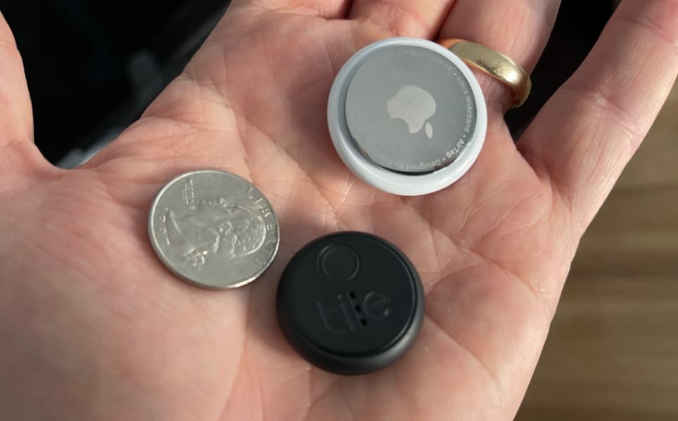
    Apple's AirTag measures in at 1.26 inches in diameter, and it has a height of 0.31 inches, or 32mm and 8mm respectively.
    alt text
    Part of that is going to be due to the inevitable bulk of the surrounding enclosure, yet I think I might be able to get in the ballplark to the same dimensions with a DIY solution that leverages inexpensive sample containers as the enclosure:
    https://www.amazon.com/gp/product/B00YOS7N4A/ref=ox_sc_saved_image_4?smid=AS7VB9OCJNT4I&psc=1
    I say that because a surface mount CR2032 holder needs a footprint of around 25mm in diameter. That allows for a little extra space for the module antenna to overhang without hovering over the GND plane. That means I can craft a solution that's close to the one I had already done 5 years ago:
    https://www.openhardware.io/view/510/Multi-Sensor-TempHumidityPIR-LeakMagnetLightAccel
    but this time it can be just an MCU (nF52805 this time around) with a buzzer and LED, without the need for all the other bells and whistles. I'll try to see whether I can fit a Tag-Connect footprint onto it. I'm fairly sure it can be done. By the way, I've looked at a lot of nRF52 "beacons", and none of them come with a buzzer, nor would it be easy to add one, so that's what necessitates this as a DIY project. The only reason the earlier project had the big 10pin box connector was that it was very easy to plug it into an nRF52-DK for J-TAG using just an IDE ribbon cable with that particular connector. With time comes better options, and so this time it'll be ixnay to the box connector.


  • Hero Member

    I had to open one up to get this photo, but this is what the inside of a Fanstel beacon looks like:
    fanstel_beacon.JPG

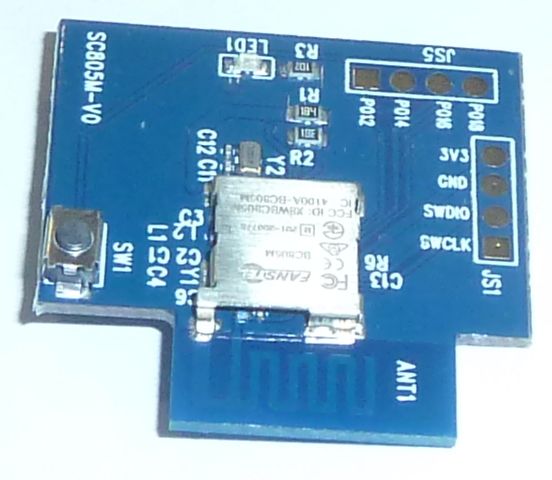
    Obviously it's meant to be programmed with pogo pins. Interestingly, although the case is black, it has some translucency to it, so maybe the LED can shine through it enough to be visible.

    It has one intriguing feature though that none of the aliexpress beacons have, which is that they also expose 4 other pins along the JS5 connector outline. This opens the possibility that with the right ultra-thin buzzer, the right resistor, some UV glue, and some solder, it just might be possible to kludge a buzzer onto this board and still fit it back in its case, which looks like this:
    alt text
    which has dimensions: 30x31x10mm (9300 mm^3) , which is just a tad narrower than the Apple AirTag but 2mm thicker. Assuming that the apple airtag is fully optimized for size, I'd say that's pretty good. As a further datapoint, my el cheapo keyfinder tag that I took apart earlier in this thread is 47x31x6mm (8,742 mm^3), so thinner than either than either the AirTag or the Fanstel, but obviously 50% longer. Being circular, the airtag has the least volume, at just 6,430 mm^3, whereas the sample case I linked above has a radius of 31mm but a thickness of 15mm, giving it a volume of 11,114 mm^3, so hopefully I can find a thinner sample jar with less volume to repurpose for my DIY enclosure, although given the cheap price for sample jars I could certainly live with 15mm if I can't find better. I do like that the sample jars appear to be very clear, and since they're acrylic, I assume (?) they won't yellow if kept away from UV light sources like the sun.

    Anyhow, I estimate that a 2mm thick buzzer might not exceed the height limitation imposed by the casing, so today I ordered a few different 2mm thick buzzers from mouser to try and see if I get lucky. 🙄 If that fails, then there does exist at least one buzzer that's 1.9mm thick that might be able to squeeze in, but that appears to be the minimum possible buzzer thickness, at least for what's available on Mouser. In general thinner means both less loud and more expensive, so there's that as a trade-offs.


  • Hero Member

    @ejlane said in Most reliable "best" radio:

    They don't automatically come with the cables, which could be a pain if you didn't know to add them to the order. Though this way I guess if they wear out it's easy to just buy the one without the other...

    I ordered this one: https://www.tag-connect.com/product/tc2030-idc-nl-10-6-pin-plug-of-nails-spring-pin-cable-with-0-1-ribbon-connector-10-version
    and it looks to me as though the cable will be baked right into it. I ordered the 2.54mm pitch cable connector because it should be relatively easy to create an adapter board for it using 2x3 male pin header that I already have.

    I also ordered the little holder pieces that you mentioned: https://www.tag-connect.com/product/tc2050-clip-3pack-retaining-clip though I didn't buy their $1 paper clip for holding it. Sheesh! The audacity.


  • @NeverDie said in Most reliable "best" radio:

    @alphaHotel Thanks for your post. It reminded me that for one-time programming, all one really needs is just the through-holes on the board. You can then bend the pins on a male header to create a kind of "weave" pattern, and that alone is enough to hold it into place during the programming, after which you can simply remove it. I've confirmed this works at 2.54mm pitch, and so I'll try it at 1.27mm pitch. I expect it should work well with that too.

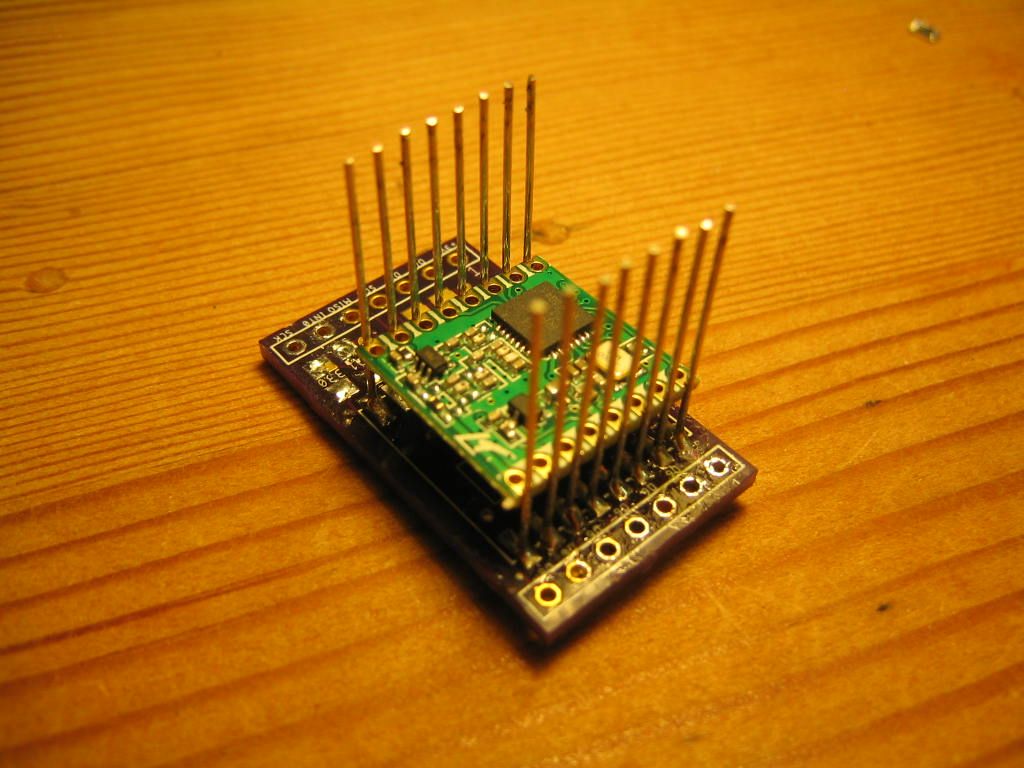
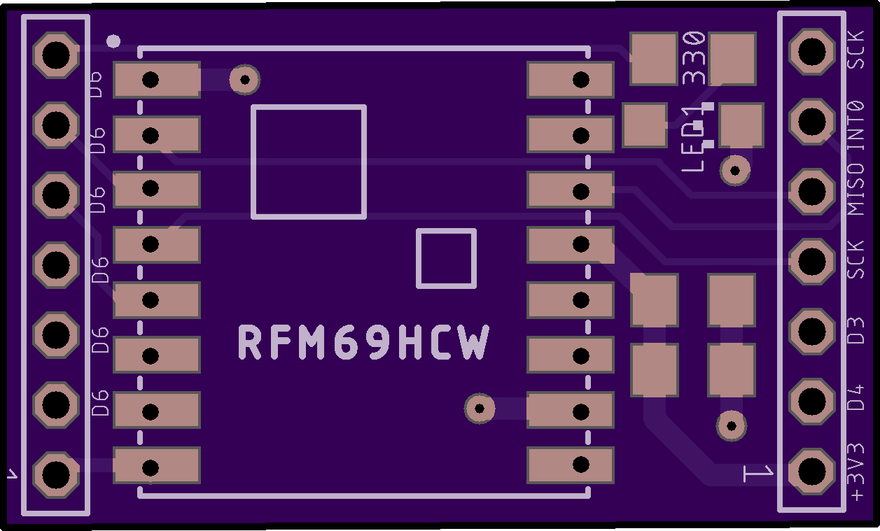
    Those castellated notches of the RFM69XXX radios and ESP12 radios appealed to me as an opportunity to use springs in a different way. I think I talked about that in an earlier post. Well, I designed one based on NeverDie's radio boards and the picture below is how it turned out. For the springy things I used high-carbon-wire (guitar strings.) I had to cut the wire with a Dremel grinder because shears would bend the wire at the cut. The springs don't need to be nearly this long, though it does allow for a lot of flex when entering the jig at the top. At the pads on the board I used large via's (about 21 mills, I think) so that I could solder both sides of the board for rigidity. This would all for the rapid testing of dozens of radios if necessary.

    As you know, I am having trouble with bootloading so I haven't implemented the idea yet. But I'm really pleased at how the dimensions worked out and the spring tightness. I got this idea from looking at RJ45 connectors and thinking that I could do something like that.

    I tried a few pogo-pin designs for ESP programming, and they work... but not easily. This design is a snap. I think I left behind the design files.

    IMG_0012.JPG

    OSH_ParkImage.png


  • Hero Member

    Clever! Thanks for your post. Exactly which type of guitar strings do you buy that work the best? i.e. do you try to match the castellation diameter with the diameter of the string? Also, regarding your layout for them on the PCB, how do you decide where to position them? i.e. do you use a formula or something, or do you eyeball it and take a WAG? And how do you keep them perpendicular to your PCB while you solder them? Or do you just fit a bunch in, force in the part, and then use the tension to hold them in place while you solder?


  • @NeverDie said in Most reliable "best" radio:

    Exactly which type of guitar strings do you buy that work the best? i.e. do you try to match the castellation diameter with the diameter of the string?

    The brand is D’addario, I think. It measures 22 mills, and yes, I was trying to fit the diameter of the castellation. Looking online I see there are many different types, but I just asked for high carbon steel at the local music store.

    @NeverDie said in Most reliable "best" radio:

    Also, regarding your layout for them on the PCB, how do you decide where to position them? i.e. do you use a formula or something, or do you eyeball it and take a WAG?

    It was a calculated WAG, but it worked. I wanted the rows of vias to be about 10 to 20 mills closer than the radio’s two rows of castellated pockets. The distance between the radio's castellated surfaces measures 616.5 mills. The distance between the via centers is 622.0 mills. Subtracting the 23-mill hole diameter would result in the via surface-to-surface distance on the board of 599 mills. The 17.5 mill difference (616.5 - 599) means the radio would not be able to slide all the way to the bottom. When engaged, the radio slides down within 1/4 inch of the board while the springs tops splay outward slightly.

    @NeverDie said in Most reliable "best" radio:

    And how do you keep them perpendicular to your PCB while you solder them?

    You are asking all the right questions. Since OSH Park gave me 3 boards, I used one at each end of the wire. I think I used some blue-tac under the target board and maybe some blue-tack, or tape, to hold the place-holder board at the other end of the springs. Then I soldered top pads of the target board, flipped the assembly over, remove the target blue-tac, and soldered the bottom via surface.

    To do this again, I would add SMD pads on the bottom of the board that would give more soldered rigidity to the spring base. I also had some slight alignment problems as the vias are not exactly straight. It was my first KiCad project; thank you for encouraging me to try. KiCad probably has an alignment tool. The other change I might make is to cut the wires down to about 0.5-inch, or less. The existing 0.9-inch length was helpful for assembly and soldering access, but my fear is that each of these longer wires form a potential antenna. I wouldn't change any of the other dimensions.

    You are welcome to 'my' KiCad file based on your design. Is there somewhere that I can drop it. I can't do it here.


  • Hero Member

    @Larson said in Most reliable "best" radio:

    You are welcome to 'my' KiCad file based on your design. Is there somewhere that I can drop it. I can't do it here.

    Thanks! No need to share the file as I'm not presently using RFM69 in a manner where I would need it, but your answers told me all I need to know for when any kind of similar need arises in the future. 🙂


  • Hero Member

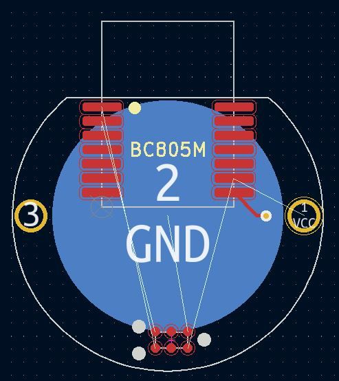
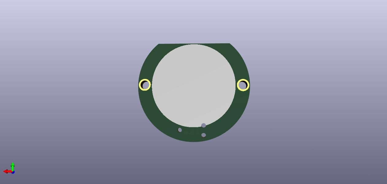
    It looks as though that by rotating the TAG-CONNECT footprint a few degrees, I can fit the landing pads onto a coincell size platform without having its holes penetrate into the CR2032 connection pad.
    TAG_CONNECT_rotated.JPG

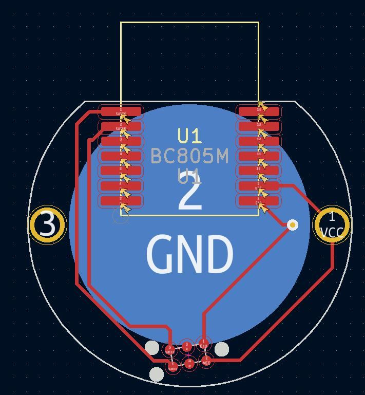
    The diameter of the PCB is 24mm. However, one of the three alignment pins might not be well supported, so maybe pushing the footprint up would be the better way to go with this. I don't see that having a hole in the GND pad of the CR2032 will make any meaningful difference. I do think that having it close to the edge, though, is probably a good idea, so that the TAG-CONNECT can hook up without hitting the metal of the coincell holder.


  • Hero Member

    So, I think I'll opt for taking a slight bite out of the GND pad in exchange for having a sturdy connection:
    TAG_CONNECT_horizontal.JPG
    TAG_CONNECT_3D_render.jpg


  • Hero Member

    Well, having now test driven some of the 70db and 80db buzzers, I just don't think they're loud enough to guarantee being heard under worst case scenarios. So, I found a buzzer that promises a minimum of 100dB...if powered by 150ma at 5v. Argh. So, I guess I'll be using two coincells now, plus some other support chips, in order to guarantee I can find the beacon under even adverse conditions. Maybe it's not so bad after all though, as I perhaps won't have to be concerned as much with the voltage droop that's common in CR2032's. Also, 100dB is darn loud, so that should make finding the thing by ear a lot easier.

    I wonder just how long a burst of sound needs to be in order to be heard clearly? At that level of consumption, I only wanting it buzzing for the absolute minimum.


  • Hero Member

    I sent a couple boards off to the fab, but it's now more obvious than ever before why the pro's prefer to mount a ceramic disk piezo in the case, and that's because it simply takes up too much space on the PCB. With a loud enough buzzer surface mounted on the PCB, I had to do tons of routing origami to make the parts fit. I could take another stab at it using 0402 instead of 0805 parts, but then soldering will be harder in the trade-off. For that reason, I think the short-term solution may be gluing a large surface mount buzzer to the inside top of an enclosure and then running wires from that to the PCB....except then when I screw on the top, I'd be twisting the wires. Ugh. Maybe I could pre-twist them in the wrong direction so that twisting them during the screw-on makes them untwisted when it's all finished. I'm starting to feel more like a system architect than a hobbyist. 🤣 On the other hand, if I could glue the PCB to the buzzer, then it would all rotate together and life would be good. Hmmm.... Yeah, maybe that's the best option.

    Another thing: it's not easy finding coincell holders that will stack two CR2032's to yield a 6v voltage. I've been down this path before on a prior occasion, and, IIRC, the solution is to stack the two coincells inside a kind of "drawer", which then slides into a clip cavity on the PCB. That does tend to add some amount of height, but it also avoids the two coincells from slipping apart and/or shorting-out against the metal of the holder. The downside is that it has a slightly bigger footprint than the non-drawer types.

    On the other hand, with a flat two-cell design, there would be plenty of room for even a large SMD buzzer. Hmm.... Maybe not a bad idea.


  • Hero Member

    OK, I think I may have found a solution that I could mount external to the enclosure:
    savior.JPG
    It promises to deliver an ear-splitting minimum of 110dB of sound pressure while drawing no more than 5ma. So, the benefits are:

    1. Plenty loud. Even if buried in some box, I bet this could be heard.
    2. A voltage range of 1 to 40v, with 9v being nominal.
    3. Externally mounted, so not muffled by the PCB casing
    4. Only requires just a couple of solder pads on the PCB, which won't consume much PCB real estate.

    Downside: runs at 9v for maximum effect. Datasheet doesn't indicate the sound pressure level at a lower voltage, so I'll have to buy one to test it out. Maybe this changes the form factor to more of a 9v battery size if that's what it takes. Though not ideal, that wouldn't be so bad.

    Re-thinking it all now, maybe heatshrink alone would be a "good enough" enclosure that I needn't bother with a rigid enclosure? Or, better yet, since PCB's are so cheap, maybe I build an enclosure out of a stack of custom routed FR4? That would give me a lot of flexibility without having to manually fabricate something. The FR4 could give rigid protection against dings and dents. Then bolt it together through 4 corners and, presto!, a sliced stack enclosure, similar to how some raspberry pi enclosures are fabricated:
    alt text
    or
    alt text
    where FR4 could be used instead of plastic, simply because that's something a PCB house is already good at routing and shipping. Rock bottom PCB's tend to be thin, though, so this might only be economically viable for a small device, such as what I'm attempting to make. Obviously, custom 3D printing something will probably be more economical, but that comes with its own set of hassles and costs, whereas a sliced enclosure might be easy to throw together.

    [Edit: I just now priced it out at JLPCB, and, for instance, a 50mmx50mmx1.6mm slice with a 30mm diameter hole in the middle would cost about $0.20/slice at quantity 100. i.e. low enough to be interesting. ]


  • Hero Member

    Reporting back: I tried it out, and that thing really is ear splitting when powered by 9 volts. It's so loud that even if I completely cover the opening, it's still loud. That's great. That means that even in a worst-case scenario where it's buried inside some sealed container, it's extremely likely I'd still be able to hear it. After all, a locator that can't be found is no good. Although it's probably overkill, when it doubt build it stout. 😀

    Also, I ordered some PCB slices to try making an enclosure that way (as illustrated in the sliced enclosure photos above), so we'll see how that goes.
    pcb_spacer.png


  • Hero Member

    I discovered by accident that if I place an order with JLCPCB and then place a parts order with LCSC before the JLCPCB order ships, then LCSC will discount the shipping cost for the LCSC parts order, even though they can't actually combine shipping. Huh? This was actually my first time ordering parts from LCSC, so I'm just passing along the finding in case it might benefit anyone who might be reading this.

    BTW, Intel recently predicted the chip shortage will last into 2024. 🤦‍♂️


  • Hero Member

    The strange thing about buzzers is that most of the datasheets express their SPL measured at a distance of 10cm, whereas, in contrast, most other sound sources are measured at 1 meter. Fortunately, from plugging the numbers into this conversion calculator: https://www.omnicalculator.com/physics/distance-attenuation
    it turns out you can take the oddball buzzer datasheet measurements and convert them into conventional one meter SPL measurements by simply subtracting 20dB from the 10cm datasheet value. So, in reality, what the datasheet calls a "100 dB" buzzer is actually an 80db buzzer for purposes of standard comparison to most sound sources.


  • @NeverDie Soldier on, my friend. I love reading, but I've got nothing to add other than to report that I'm moving on to the radio portion of the barebones design. Maybe I do have something to add: I found that having JLCPCB/LCSC fabricate parts was really easy and not very expensive. The required EasyEDA design environment, I recall, linked LCSC inventory with JLCPCB quite seemlessly. As usual, for me, the learning curve took a long time. I think there were limits that wouldn't allow for exotic parts. That is not a problem for me and my simple ways. But shipping confusion did not exist as it was a combo thing. The minimum order of 5 and the single-sided fabrication were limitations that I could work with. Manually soldering SMD's is really hard and JLCPCB makes it so easy.


  • Hero Member

    @Larson Thanks for your post. With parts getting ever more tiny, I think that would be a nice resource to leverage.

    I'm presently learning more about buzzers than I ever wanted to know, but I'm having to discover the critical knowledge by experiment because the datasheets don't really adequately characterize them. In the end I think it's going to be a tradeoff between form factor, sound level, battery life, and the number of components needed to assemble the objective, as well as ease of assembly. My first design was this:
    alt text
    and I have a lot of alternate designs in the pipeline that I'll want to compare against it before picking a winner. Because of the buzzer dynamics, I have to actually build them in order to do a proper job of comparing them. For instance, the buzzer on this prototype is rated at 100dB at 10cm, but, as I've learned, that really only means 80dB at 1 meter if powered at 5v. But what is the SPL if powered at 3v or even 2v? Those are in the acceptable voltage range, but the datasheet doesn't say, so I have to buy buzzers and try them out in order to find out that kind of info. And it's not as straightforward as you might think, because the resonate frequency seems to change depending on the voltage. So, I have to discover that as well in order to do a proper apples-to-apples comparison.

    Further complicating matters is: how much current can a coincell really be counted on to deliver, especially as it ages and as its voltage drops. It turns out that answer isn't straightforward either, because it depends on how long you draw it for, and then there's a recovery period after which you can draw more current than if you don't wait for a recovery period. And how long do you need to wait, and so forth. Try figuring that out from a datasheet. That type of essential info just isn't there, and yet I need to know it if I'm going to compare the design in the photo against another design which might use, say, a CR2477 or a CR2450 or a CR123A, etc. Probably somewhere someone has built a coincell simulator to answer these types of questions. I presume that Durael or Energizer have the info but decided not to include it in their datasheets, maybe for marketing reasons.

    So, to cut through all that, I'm taking the empirical route of build-and-test for a number of different design concepts, and I'll use the results to zero-in more quickly on the winner.


  • @NeverDie said in Most reliable "best" radio:

    because the resonate frequency seems to change

    Ahhh, I have something to offer. I remember way back when playing with piezo buzzers (something that is part of my mole project and in use today unfortunately) I remember incrementally changing the PWM frequency and duty cycle in the loop. I may be off base because I really don't understand what you are doing. But I remember that there is a sweet spot (resonant frequency, perhaps) where the sound would just pop. I've seen this in vocal quartets too (we are talking humans) when they hit some vibe some kind of God's amplifier gets invoked. It is really cool unless one has hyperaccousis, as I do. So I run an hide, but marvel at the science.

    @NeverDie said in Most reliable "best" radio:

    compare the design in the photo against another design which might use, say, a CR2477 or a CR2450 or a CR123A, etc. Probably somewhere someone has built a coincell simulator to answer these types of questions.

    During dev, I try to overpower with big batteries, or lines to sort it all out before playing with the smaller cells. Understand the demands first, then find the cell that can deliver. The LIR2450 seemed to deliver a good punch of curent that can carry radio transmission peaks of a ESP8266, 400uF caps helped. Nice thing is that you can control the timing of the peak audio with any other peak load... like a radio or something and prevent an overload.


  • Hero Member

    @Larson said in Most reliable "best" radio:

    But I remember that there is a sweet spot (resonant frequency, perhaps) where the sound would just pop.

    Yup, I've noticed the same, if by "pop" you mean becomes noticeably louder. It's not free though, as the current consumption also hits a peak at that frequency, which is yet another way to identify where the "pop" happens. But, anyway, yes, I agree, that is the magic sweet spot, and it's absolutely worth the extra current.


  • Hero Member

    I ran into a "gotcha" with the larger piezo buzzer. It turns out that they have high enough inherent capacitance that you need either a resistor or something else to "drain" them during the off-phase of a square wave. Otherwise, the sound is minuscule. According to my Fluke multimeter, the large piezo's have only about 24nF of capacitance. I haven't yet checked with an LCR meter to confirm.

    It turns out you can use an inductor instead of a resistor and setup a resonant circuit, which is more energy efficient than just using a resistor. So, I may try that, even though it's a more complex circuit to construct, because this way it will also increase the voltage (and hence volume) of the buzzer:
    alt text
    https://www.digikey.com/en/articles/design-techniques-to-increase-a-piezo-transducer-buzzer-audio-output

    What's also interesting is that for buzzer's with a feedback terminal, you can use a simple circuit to automagically drive them at their resonate frequency:
    alt text
    https://www.hackster.io/taunoerik/self-drive-piezo-buzzer-e9786f
    Evidently this also serves the purpose of "draining" the buzzer without using a resistor directly across Main and Ground.

    Well, by trial and error, I've determined that it takes about a 100 ohm resistor to adequately "drain" the buzzer during the low phase of a square wave. Assuming 3V, that means 300ma wasted current during the high phase. On it's face, that seems excessive.

    The small buzzers seem to neither need nor benefit from these drain resistors. I guess their inherent capacitance is simply too low to matter.

    [Reporting back: I tried out the self driving buzzer circuit, and 1. it works at higher voltages of around 9-10v, and 2. even then it isn't as loud as a proper square wave at 3v. So... I'm nixing that idea. Besides, it's rather fiddly as to getting the component values just right in order to work, and who knows how much variation there might be in the manufactured piezo buzzers.]


  • Hero Member

    Fun to see what hobbyists can achieve when they stick to it long enough:
    I Landed A Rocket Like SpaceX - Scout F – 07:05
    — BPS.space


  • @NeverDie Yep, that rocket stuff, and that dedication-to-task stuff, is pretty cool. Thanks for sharing - very inspirational.

    At a more modest level ... I received the Atmega 328P programming harness/clamp you recommended long ago. Nice. And your barebones board loaded with my RFM69HCW jig are working nicely. Also received: a bunch of your suggested radios and the carrying boards. Time, I need time. Can't thank you and @alphaHotel enough for the encouragement. I look forward to reporting if only to chronical for my own record and possible use for others.

    I hope it doesn't take me 7 years, but it may. Now all I need is a bunch of 48 hour days.


  • Hero Member

    What I've learned lately about buzzers, through experimentation, is that to get maximum loudness I need to drive a buzzer within about plus-or-minus 5Hz of its optimum resonance frequency. More than that and the loudness drops off precipitously. Unfortunately, manufacturing variance is probably more than plus-or-minus 5Hz, so that's a potential problem. The voltage supplied on the feedback pin of a piezo is only around 50mv, which is too low for an for an MCU to measure accurately without some kind of extra circuitry to help. It would be nice if the system could self-calibrate the driving frequency to match the inherent resonance frequency of the buzzer.

    Meanwhile, I'm switching over to an H-bridge for driving buzzers, because an H-bridge not only efficiently drains the charge that builds up on the piezo buzzer but it also effectively doubles the peak-to-peak voltage seen by the buzzer. At these low voltages, more apparent voltage means more loudness.

    When I started this project, I really didn't expect that the buzzer part of it would turn-out to require as much attention as it has! Sure, getting some amount of loudness is not a problem, but really maximizing loudness at these low voltages, while maintaining a tiny footprint and ease-of-assembly, isn't as easy as you'd think a priori.


  • @NeverDie said in Most reliable "best" radio:

    It would be nice if the system could self-calibrate the driving frequency to match the inherent resonance frequency of the buzzer.

    Perhaps an initialization User Interface selection? If the big picture is arranged and the region is only 5 Hz, then maybe a centeral default with an user option would be acceptable. Start slow, then rise in 0.25 Hz increments? If the user doesn't repond, then the default is mid-range. As in life, you can only help people so far. I think my mother tried to tell me that once.

    Caveat User (Emptor).


  • Hero Member

    @Larson said in Most reliable "best" radio:

    @NeverDie said in Most reliable "best" radio:

    It would be nice if the system could self-calibrate the driving frequency to match the inherent resonance frequency of the buzzer.

    Perhaps an initialization User Interface selection? If the big picture is arranged and the region is only 5 Hz, then maybe a centeral default with an user option would be acceptable. Start slow, then rise in 0.25 Hz increments? If the user doesn't repond, then the default is mid-range. As in life, you can only help people so far. I think my mother tried to tell me that once.

    Caveat User (Emptor).

    You mean make it user selectable?

    I'm toying with the idea of an initial calibration using equipment not on the PCB. That's how I arrived at the optimal frequency on my prototype. However, it's unpleasant listening to the frequency sweeps. Even my wife complained about it, and she was in a different room entirely. The only upside is that it's sure to work.

    I found a good size for a shell, using a Govee temperature-humidity sensor:
    alt text
    It runs on a CR2477, so it has plenty of depth to it. Nobody seems to shell the shells though, and it would be a shame to canibalize their sensor just for the shell alone. I guess I'll have to 3D print something....


  • Check out the Hammond 1551V1gY (vented) or 1151SNAP1GY (unvented).
    They look like they are about the same size. I've been using the vented ones for temp/humidity sensors. Not as ugly as most project boxes.


  • @NeverDie said in Most reliable "best" radio:

    The only upside is that it's sure to work.

    Very, very funny. Fell off my chair, funny. I had a similar experience with testing buzzers only I failed to recognize the upside/benefit. I ended up putting a switch on the speaker effect to maintain domestic tranquility.

    Yes, frequency user selection was my thought. It sounded like the mV range detection/optimization was too complicated. If the design gets close enough to the expected range, then punt to the user for fine tuning.

    Shells: Unless a resonant cavity is important, how about a simple tic-tac container with a pre-drilled speaker hole and some hot glue? Maybe a pezz container, if they make those any more? Even a Gatorade bottle cap filled with epoxy might work (use cellophane to cover/embed the mechanical parts of the speaker.) Failure has taught me many things, and this is one of them.


  • Hero Member

    Good suggestion on using a tic-tac container. It never would have dawned on me. Too bad I'm on a Keto diet, but I guess I could give the tic-tacs to my son, who doesn't need to diet.

    I may have spoke too soon that the nRF52 isn't sensitive enough to read the feedback voltage precisely enough. It turns out to have a 0.6v internal voltage reference, and it has a 12-bit ADC, so in theory it could measure in increments of as little as 0.6v/4096=0.146millivolts. Is that good enough? I really don't know, but I'm going to give it a try. The closer the piezo gets to resonance, the more the feedback voltage should shoot up. I'd be counting on it shooting up by a lot when it hits resonance. So, I just now uploaded the files to a fab for a PCB which can do those measurements, and hopefully I'll receive it in about a week. 🙂


  • Hero Member

    @nagelc said in Most reliable "best" radio:

    Check out the Hammond 1551V1gY (vented) or 1151SNAP1GY (unvented).
    They look like they are about the same size. I've been using the vented ones for temp/humidity sensors. Not as ugly as most project boxes.

    Good find! I like the vented ones, as it look like they would let out a lot of sound.


  • Hero Member

    @nagelc said in Most reliable "best" radio:

    Check out the Hammond 1551V1gY (vented) or 1151SNAP1GY (unvented).
    They look like they are about the same size. I've been using the vented ones for temp/humidity sensors. Not as ugly as most project boxes.

    @nagelc I ordered the white version of the vented model you referred to so that I can give it an up-close looky-loo. I also found an interesting "similar but different" vented enclosure from New Age Enclosures, though at twice the price, which I also ordered for comparison:
    alt text
    https://www.mouser.com/ProductDetail/789-P1A-151510
    With benefit of hindsight, maybe I should have started to look at possible enclosures from the get-go, because, depending on what's available, that may very well determine what form factors are even worth considering. 🤦 i.e. the project will end-up needing to fit the enclosure, probably not the other way around.


  • Hero Member

    I think I may now finally understand the purpose of the optional S0, LENGTH, and S1 fields in the nRF52 packet frame. The datasheet gives very little insight into them, so I had previously disabled those fields just to avoid the topic altogether because it seemed so obscure. However, in trying to figure out how to send/receive packets between an nRF52 and an old-style nRF24L01+, the puzzle finally makes sense: they are there to either 1. provide a means of compatability with the nRF24L01's Enhanced Shockburst, which puts a 9-bit field in the middle of the frame:
    alt text
    or 2. allows you to roll-your-own super Enhanced Shockburst with extra bits (in which case standard nRF24L01P ESB compatibility goes out the window). Well, for a host of reasons, I think nRF24L01p compatability is worth enduring an extra 9 bits of airtime, so I'll go that route and configure the nRF52 accordingly now that I've inferred what those fields are meant for. 🤠


  • I like your ideas. Is there a circuit for common mode rejection? It would be worth exploring. And using a test port for different pull-up resistors, better yet a variable resistor, would allow for testing.


  • Hero Member

    Reporting back on the E01-2G4M27D radio's that I had referenced earlier. For those who don't remember, these are nRF24L01P radios that have been upgraded to use a 27dBa PA and, allegedly, other higher quality components (https://www.ebyte.com/en/product-view-news.aspx?id=450). 27dBa = 0.5 watt. For comparison, the maximum Tx power of a plain nRF24L01 is just 0dB. I had occasion to try them out today, and they appear to perform extremely well, even at 2mbps while transmitting over the worst-case transmission path in my house that I've been using to test all the radios on.
    E01_2G4M27D.JPG
    I'd venture to say that in terms of reliably getting a packet through to its destination, they outperform all other enhanced nRF24L01P's that I've ever tried previously. If you opt to try them on the test platform, as I have done, I recommend you upgrade your BoB capacitor to 100uF or 200uF, because 10uF doesn't seem to be enough when transmitting from somewhat weak batteries. Nonetheless , 10uF is sufficient if powering it from a really stiff power source. Ironically, they vastly outperform the 2.4Ghz LoRa radios that got me started on this whole mini-blog in the first place.

    Looks as though you can buy them on sale at $4.59 each: https://www.aliexpress.com/item/2255800350626109.html?gatewayAdapt=4itemAdapt
    No, they don't come with the antennas. You'll have to source those separately.

    I'd say the main downside to these modules is that there does not appear to be any way to dial-down the transmission power, so that you only use as much power as you really need to fit your circumstances. There's no reason that such a module couldn't be designed and built (just as the RFM69HW allows), but, AFAIK, there aren't any on the market like that for the nRF24L01P. It's such an obvious enhancement that I'm surprised none of the vendors have offered it, even if it requires extra pins. Maybe someone reading this knows of one? If so, please post.


  • Hero Member

    🤦 Doh! It just occured to me that rather than being a fixed output power, maybe these modules actually do have adjustable gain via adjusting the power output of the nRF24L01P:
    nRF24L01P_tx_power.png

    That would perhaps mean that you could adjust the power output to be 27dB minus 18dB = 9dB? i.e. they effectively offer a gain of 27dB to whatever output power your radio chip already has? Is that how PA's work? Or, instead, would it just be blasting out mostly noise at 27dB if I were to set the nRF24L01P's output power to -18dBm? I'm guessing the former and not the latter, but unfortunately I don't have any radiated RF power measuring equipment that might tell me the answer. Anyone know? Perhaps measuring the current consumed during transmission would tell the tale, as one could infer the output power from that. Hmmmm...... Worth a try. Might be able to approximate the answer from that. If it turns out that they are adjustable in this manner, then I would think they are pretty awesome as a default "go to" module for just about anything. i.e. you'd have good communication even on the low-end of 9dB, but you would also have plenty of headroom to notch it up to a higher output power if it were truly necessary to cover whatever contingency you might run into, provided it remains within the legal limits of whatever your jurisdiction is.

    I once tried (and reported on) a 4watt 2.4Ghz amplifier that you can buy on amazon, and it had a "sweet spot" for input power that it could amplify from, but below that sweet spot it didn't do much good at all. Perhaps that's a more accurate model of how this works in real life?

    Looking at the manual, it does say the output power is multi-level software adjustable, so there's hope. https://www.ebyte.com/en/downpdf.aspx?id=450 I don't see that it offers any hints beyond that though.


  • Hero Member

    Well, attempting to answer my own question above, here is the power profile of the E01-SG4M27D when the nRF24L01P is set to 0db (plus whatever power the PA on module boosts that to):
    E01-2G4M27D_Full_Power.png

    Here it is when the nRF24L01P is set to -18dBm ( (plus whatever power the PA on module boosts that to):
    E01-2G4M27D_Low_Power.png

    So, it looks as though the latter is the current is roughly 1/3 of the former, and since the voltage is the same, that would imply that the power is about 1/3 also. However, if my earlier theory was right, then the second chart should be showing a maximum of about 7.4mw, as compared to the theoretical 500mw of the first chart.

    So, really, neither chart makes much sense. 3.3v x 580ma = 1.9 watts and 3.3v x 180ma = 0.594 watts. Well, I guess that's wrong if the radio module converts the 3.3v to a lower voltage for running the radio at via an LDO, which means it disappates the difference as heat. Still, the ratio between high and low Tx power is something like 3 to 1, whereas in theory it should be more like 67 to 1. So, I really don't know what to make of all that, other than the PA doesn't have much dynamic range to it. Does that extra power at the low end translate into proportioinately more radiated RF? I have no way of knowing, as this is the limit of what I can test with the equipmet that I have. I'd need something which can measure actual radiated RF.

    This guy demonstrates how that might be done:
    RF Power Watt Meter – 06:43
    — 0033mer

    In a nutshell, it would require both the power meter and, in this intance, an attenuator to go along with it.

    I suppose an alternate, non-elegant way to solve the problem would be to have an array of different nRF24L01 modules, each optimized for a different power level. Then, by selecting the right CE pin, you could switch among them for the desired power level for a transmission. Not completely outlandish if size doesn't matter so much, because nRF24L01P modules, in whatever flavor, are generally fairly cheap--perhaps cheaper than buying the $80+ worth equipment needed to measure RF power that would probably be only one-time use. So, for a gateway, that might be a possibility. For a sensor node, probably not.


  • Hero Member

    @NeverDie said in Most reliable "best" radio:

    I think I may now finally understand the purpose of the optional S0, LENGTH, and S1 fields in the nRF52 packet frame. The datasheet gives very little insight into them, so I had previously disabled those fields just to avoid the topic altogether because it seemed so obscure. However, in trying to figure out how to send/receive packets between an nRF52 and an old-style nRF24L01+, the puzzle finally makes sense: they are there to either 1. provide a means of compatability with the nRF24L01's Enhanced Shockburst, which puts a 9-bit field in the middle of the frame:
    alt text
    or 2. allows you to roll-your-own super Enhanced Shockburst with extra bits (in which case standard nRF24L01P ESB compatibility goes out the window). Well, for a host of reasons, I think nRF24L01p compatability is worth enduring an extra 9 bits of airtime, so I'll go that route and configure the nRF52 accordingly now that I've inferred what those fields are meant for. 🤠

    It worked! 😄 😃 🙂 Well, sort-of. I have it working using the five byte address 0xE7E7E7E7E7, which dodges the question of how the address bytes are ordered over the air in one scheme versus the other. That's the next puzzle to solve. You might think this would be easy to solve, as I did, but so far not.

    Here's part of what's weird (this is taken from the nRF52 datasheet):
    nRF52_onair_byte_ordering.png

    Can you see the disconnect? On the nRF52 the LENGTH field comes in the middle of the 9 bits, whereas on the nRF24L01 ESB it comes at the front of the 9 bits.

    Also, I haven't been able to get any non-repeating address to work yet. e.g. x0101010101 works, and so does 0xE7E7E7E7E7, but that's a rather limiting type of address to rely upon, though I suppose I could live with it if I had to. Go figure.


  • @NeverDie You are building a library. I don’t have the time to consume/enjoy it now as I’m deep in eldercare. But for sure, I’m coming back to your wonderful library to learn more – just later. Don’t interpret my silence as… indifference.


  • Hero Member

    @Larson No worries. It works better with feedback from a knowledgeable audience, but... that entire audience has seemingly evaporated. Nonetheless, this rubber ducking may still have some value even under the current "everyone long gone" circumstances.
    alt text


  • Hero Member

    Aha! Apparently there is some kind of undocumented difference in the way addresses are represented in an nRF24L01P vs. an nRF5x. I found this address conversion function in Nordic's "micro-esb" library (https://github.com/NordicPlayground/nrf51-micro-esb/blob/master/common/micro_esb.c ) which holds promise for illuminating what that difference is:

    esb_addressing_difference.png
    and
    address_conversion.png

    Just from eyeballing it, nRF24L01P apparently transmits in the order of most significant bits first (which is undocumeneted), as compared to nRF5x, which transmits in order of least significant bits first (which is documented). Well, that would explain why xE7 (=B11100111), worked in my earlier addressing attempt, since it is the same either way.

    Well, yes, though the algorithm is a two-step process. The bytewise_bit_swap function apparently reverses the ordering of bits in each byte, but leaves the bytes in the same order:

    1111111111111111111111110100 -> 11110000111111111111111100101111
    1111111111111111111111110011 -> 11110000111111111111111111001111
    1111111111111111111111110010 -> 11110000111111111111111101001111
    1111111111111111111111110001 -> 11110000111111111111111110001111
    1111111111111111111111110000 -> 11110000111111111111111100001111
    

    The radio address config section then reorders the sequence of the bytes. The net effect is the same as what I had guessed.
    Well, this does explain why on the nRF5x, the "prefix" comes after the address section in the above diagram. My original impression had been that it was a poor choice of nomenclature.

    Next I need to test this new theory on the hardware and see if it works.


  • @NeverDie said in Most reliable "best" radio:

    I suppose an alternate, non-elegant way to solve the problem would be to have an array of different nRF24L01 modules, each optimized for a different power level.

    Does the optimization mean different HW components with different RF_PWR settings? If the HW remains the same then one could incrementally change the RF_PWR level in the loop, right? Perhaps even by using two input pins one could control the RF_PWR level settings manually. The pins determine 00, 01, 10, or 11 and that gets fed to RF_PWR. That might be easier.


  • Hero Member

    @Larson said in Most reliable "best" radio:

    @NeverDie said in Most reliable "best" radio:

    I suppose an alternate, non-elegant way to solve the problem would be to have an array of different nRF24L01 modules, each optimized for a different power level.

    Does the optimization mean different HW components with different RF_PWR settings? If the HW remains the same then one could incrementally change the RF_PWR level in the loop, right? Perhaps even by using two input pins one could control the RF_PWR level settings manually. The pins determine 00, 01, 10, or 11 and that gets fed to RF_PWR. That might be easier.

    Is your two pin solution referring to picking different modules, or to somehow adjusting the Tx power on one module? Not really following what you mean there. Since all the nRF24L01 modules use SPI, what I imagined was a separate chip enable line for each one, which would make it very easy to select among them. Indeed, that's the very definition of how SPI works. Straightforward.


  • @NeverDie said in Most reliable "best" radio:

    two pin solution

    Sorry, sometimes when I reread what I wrote, I don't understand it either.

    My suggestion was to use only one radio and rotate different RF_PWR settings into the radio from the Atmega328p chip. That could be done by different means: 1. in the loop every 10 seconds or so for testing, or 2. by using GPIO pins defined as inputs, or 3. since we are talking radios, the power level could be transmitted to subject radio, read in code, and changed on the fly, or 4. any variety of other means (sensed light, temperature, vibration...)

    For example, I'm looking at your barebones board right now. The radio module I'm using (RFM69HCW) is mounted on the first 8 pins of the headers that include SPI connections. Neighboring pins A0 and A1 on the barebones header are open and could be jumpered to GND (logic 0) or VCC (logic 1). The program on the 328 could sense those pins and select one of 4 power levels in the RF_PWR setting per the table you show above.

    Hope that helps!


  • Hero Member

    Reporting back regarding how to successfully transmit a packet from an nRF24L01P to an nRF5x, here's what I've confirmed (using the actual hardware) regarding the differences in how addressing is handled between the two different platforms:

    Suppose the receiver address on a particular nRF52 (let us call it nRF52#1) is this:
    prefix: 0x01
    base-address: 0xACC01ADE
    However, despite the name "prefix", we know from the datasheet that, from a temporal standpoint, when the over-the-air bits get sent, the prefix actually gets sent after the base-address. That means that if another nRF52 (let us call it nRF52#2) were transmitting an address meant to match nRF52#1, then the over-the-air bits, which are sent least-significant bit first on an nRF5x, would be sent as follows if you were writing them down left to right in temporal transmission order:
    (reverse 0xACC01ADE) followed by (reverse 0x01)
    Hence, from a certain twisted perspective it does make sense to call 0x01 a "prefix", because this is the same as:
    (reverse 0x01ACC01ADE)

    So, given that, the target Tx address, from the standpoint of an nRF24L01P, concatenated together, is the very same:
    (reverse 0x01ACC01ADE)
    because an nRF24L01P transmits in the order of most-significant-bit first.
    As it turns out, this is equivalent to:
    (reverse 0xDE) (reverse 0x1A) (reverse 0xC0) (reverse 0xAC) (reverse 0x01)
    concatenated together.

    That number turns out to be:
    0x7B 58 03 35 80

    QED.

    HOWEVER, worthy of note: when you send that address over SPI from an atmega328P to an nRF24L01, the order of the bytes (but not the bits in the bytes) is again reversed. Confused yet? That means the temporal order of the bytes sent over SPI to the nRF24L01P is actually:
    0x 80 35 03 58 7B
    from left to right. i.e. 0x80 gets sent over SPI first, then 0x35, and so on. "Why is that?" you may ask. It's because, as per the nRF24L01 datasheet, the target address is sent LSByte first over SPI:
    nRF24L01_address_LSByte_first.JPG

    Regarding how to configure the S0, LENGTH, and S1 fields on the nRF52, it makes sense to do the following:
    S0 = 0
    LENGTH = 6
    S1=3

    because then the LENGTH field is properly alligned with the LENGTH bits transmitted by the nRF24L01.


  • Hero Member

    To memorialize all that detail in easy to understand c-language code, here is a simple program which converts an nRF52 address into an equivalent nRF24L01P address that you can compile and run on any linux machine using gcc:

    #include <stdint.h>
    #include <stdio.h>
    
    // This program defines a nRF5x address and converts it into an equivalent nRF24L01P address 
    // so that a nRF24L01P radio can send packets to the nRF5x device.
    
    // Define prefix and base-address for an nRF5x:
    uint8_t this_Node_Nrf5x_Address[] = {0x01, 0xAC, 0xC0, 0x1A, 0xDE};
    
    //Note: Node_Nrf5x_Address[0] is the prefix address, and the remaining bytes are the base-address.
    
    // Define an equivalent address used by an nRF24L01 which, when transmitted, will correspond to the this_Node_Nrf5x_Address
    uint8_t nRF24L01P_Tx_Address[5];
    
    
    // Function that, given a byte, returns a byte with the bits reversed. 
    // This function is derived from the function originally provided by Nordic Semiconductor (https://github.com/NordicPlayground/nrf51-micro-esb/blob/master/common/micro_esb.c)
    uint8_t bytewise_bit_swap(uint32_t inp)
    {
        inp = (inp & 0xF0) >> 4 | (inp & 0x0F) << 4;
        inp = (inp & 0xCC) >> 2 | (inp & 0x33) << 2;
        return (inp & 0xAA) >> 1 | (inp & 0x55) << 1;
    }
    
    
    //Convert from the given_Nrf5x_Address to the equivalent nRF24L01P_Tx_Address
    void convertAddress() {
      nRF24L01P_Tx_Address[0] = bytewise_bit_swap(this_Node_Nrf5x_Address[4]);
      nRF24L01P_Tx_Address[1] = bytewise_bit_swap(this_Node_Nrf5x_Address[3]);
      nRF24L01P_Tx_Address[2] = bytewise_bit_swap(this_Node_Nrf5x_Address[2]);
      nRF24L01P_Tx_Address[3] = bytewise_bit_swap(this_Node_Nrf5x_Address[1]);
      nRF24L01P_Tx_Address[4] = bytewise_bit_swap(this_Node_Nrf5x_Address[0]);
    }
    
    //Given a pointer to an address array of 5 elements, print the address in hexadecimal
    void printAddress(uint8_t *theAddress) {
      for (int i=0;i<5;i++) {
        printf("%02X",theAddress[i]);
      }
      printf("\r\n");
    }
    
    void main() {
    	printf("nRF5x address:  0x");
    	printAddress(this_Node_Nrf5x_Address);
    	convertAddress();
    	printf("equivalent nRF24L01 address:  0x");
            printAddress(nRF24L01P_Tx_Address);	
    }


    In this example, the output is:

    nRF5x address:  0x01ACC01ADE
    equivalent nRF24L01 address:  0x7B58033580
    

    😁


  • Hero Member

    That's probably it for this thread. Proof of concept is working, and time to move on. Thank you to the few who had anything to say. Hopefully there will be more of a community again after the chip shortage is over. If not, I hope what has already been posted is at least preserved in some retrievable way so as not to be completely lost in the sands of time.


  • @NeverDie said in Most reliable "best" radio:

    not to be completely lost in the sands of time.

    Wish I could do more from my end. As long as this forum and the web exists... your library of knowledge will be of great value to me, and I presume, to others. I thank you!


  • Hero Member

    Epilogue: It turns out that although I'm now able to receive packets on an nRF52 that are sent by an nRF24L01, the payload appears to be gibberish. Argh! So close, and yet no cigar. I thought it worth mentioning for anyone who happens to be following along. I'm fairly sure it must involve those mysterious S0, S1, and LENGTH bit blocks, but as there's virtually no documentation on this aspect of things, a solution will either involve extensive troubleshooting or else locating some relevant code and figuring it out from that. In the end, I'm not sure it's worth the effort. I may just stick with plain vanilla nRF52-to-nRF52 communication, as that much is working fine and without further hassles.


  • @NeverDie A young Scott Harden taught me, via Youtube how to use a soundcard and Audacity recording SW as an o'scope. He would transmit a known preamble followed by a known pattern. I think this can be done in OSK, FSK, OOK. When the data is in Audacity, or an o'scope, then you can take your time to learn the timing of the transmitted and received signal. Seeing is believing, for me.


  • Hero Member

    @Larson Although I haven't tried it myself, I have my doubts that a soundcard would work for recording signals sent at 2mbps, if only because that is way outside the spec for normal sound recordings. However, for slow signals, yes, I can believe it would work.

    There are also software defined radio receivers that would probably do a good job of receiving and, with the right software, displaying signals. Certainly HackRF One would be one such device that could do it. I haven't tried that either, but it was designed for the purpose. IIRC, Andreis Speiss did a video on using a cheap ($10-$20) SDR to receive and decode some fairly basic radio packets. Maybe it would display them as well.


Log in to reply
 

Suggested Topics

  • 4
  • 5
  • 9
  • 2
  • 14
  • 933

0
Online

11.2k
Users

11.1k
Topics

112.5k
Posts