Sensor board with booster and supervisor
-
Hi.
As I am waiting for pcb, I am trying to miniaturize my board. It will be full smd (0805) and smaller size. And 4layers. So if use atmel 328p instead of arduino pro mini clone, I will have less chance to get a bad arduino clone.
Here what I am trying to do. It is 49x23, so I hope to be able to put two boards on a 50x50 to reduce cost.
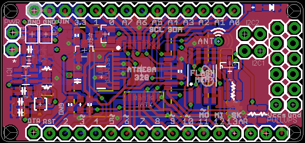
All described in my first post is integrated except 5v dc booster and one i2c (but is exposed on border, so there is 3 i2cs).
Lazy, I firstly took the moteino and added signing. then i enlarged the board to fit what I need. But I think I will not be able to fit the 5v booster. no enough place for footprint for the moment.But it is very experimental to see if it fits and it is doable. So now, I don't like the design, it is not beautiful I think and it should be better. I will make a new try from scratch this time. So here my question, if @Anticimex or @tbowmo have some recommandations, I would be very happy:
- do you think MYSConnector would be preferable than how it is? I already imagine your answer ahaha! When you decided the pinout what was your basis? do you have something with atmel rooted to the MYSXconnector 1.5?
- so if I understand right your connector, I need to make the two row, one connector.
- could you show me a screenshot of MYSX1.5 with labels. To be sure...
- as I am using booster, but with a large capa, do you have some recommandations about 4layer trace route? My first 4layer attempt so, I have read lots of articles about this, but if you have good advices...
- finally, I think it will be difficult to have nrf smd and rfm because on the left I will have dc booster and don't want to interfere with nrf, and right I will need some external connectors or additional i2c, power...
See you soon.
Ah, and I know it is Eagle. No time to learn Kicad for the moment. But maybe it will be exportable to kicad next.
-
Hi.
As I am waiting for pcb, I am trying to miniaturize my board. It will be full smd (0805) and smaller size. And 4layers. So if use atmel 328p instead of arduino pro mini clone, I will have less chance to get a bad arduino clone.
Here what I am trying to do. It is 49x23, so I hope to be able to put two boards on a 50x50 to reduce cost.
All described in my first post is integrated except 5v dc booster and one i2c (but is exposed on border, so there is 3 i2cs).
Lazy, I firstly took the moteino and added signing. then i enlarged the board to fit what I need. But I think I will not be able to fit the 5v booster. no enough place for footprint for the moment.But it is very experimental to see if it fits and it is doable. So now, I don't like the design, it is not beautiful I think and it should be better. I will make a new try from scratch this time. So here my question, if @Anticimex or @tbowmo have some recommandations, I would be very happy:
- do you think MYSConnector would be preferable than how it is? I already imagine your answer ahaha! When you decided the pinout what was your basis? do you have something with atmel rooted to the MYSXconnector 1.5?
- so if I understand right your connector, I need to make the two row, one connector.
- could you show me a screenshot of MYSX1.5 with labels. To be sure...
- as I am using booster, but with a large capa, do you have some recommandations about 4layer trace route? My first 4layer attempt so, I have read lots of articles about this, but if you have good advices...
- finally, I think it will be difficult to have nrf smd and rfm because on the left I will have dc booster and don't want to interfere with nrf, and right I will need some external connectors or additional i2c, power...
See you soon.
Ah, and I know it is Eagle. No time to learn Kicad for the moment. But maybe it will be exportable to kicad next.
@scalz
I will publish my revised sensor motherboard on the forum this week. It has MYSX 1.5.
Depending on forum feedback, this board might (or might not) evolve to a "official" MySensors board.
The MYSX specification is available here: https://github.com/mysensors-kicad/documentation/blob/master/TheMYSXconnector.pdf
And it comes in various versions to accomodate different types of boards.
My board will also come in various versions. For two different cases and a low-cost 5x5cm edition (from DirtyPCBs).
It is the "second generation" board compared to the board I did which you took inspiration from. But as you know, my first version had a few bugs, which I have resolved but yet not published.
I hope to be able to at least write a forum topic and list the board features this week. -
@Anticimex: thank you very much for your reply. So do you think I don't need to spend more time on this board, even if it is ulpnode like, and I would make it smaller (50x23 with MYSX) ?
I looked at MYSXconnector. Just two questions, then I will wait for your great work!- 20pins ok. but is it first 10 pins on first row? Maybe dumb question as I think it is group of 4x2. So 9-12 first row, and 13-16 scond row, 17-20 first row...
- On MYSX 1.3, I am little confused, pin13 SCL, pin14 SDA but pin 16 is A4???
If what I am trying to do is still actual, I will convert it to Kicad next as I saw it is possible to import eagle project. Just want to share, not compete, I don't care about this.
Anyway, I can't wait to see your board, I'm a big fan of Mysensors Team work :smiley:
-
@Anticimex: thank you very much for your reply. So do you think I don't need to spend more time on this board, even if it is ulpnode like, and I would make it smaller (50x23 with MYSX) ?
I looked at MYSXconnector. Just two questions, then I will wait for your great work!- 20pins ok. but is it first 10 pins on first row? Maybe dumb question as I think it is group of 4x2. So 9-12 first row, and 13-16 scond row, 17-20 first row...
- On MYSX 1.3, I am little confused, pin13 SCL, pin14 SDA but pin 16 is A4???
If what I am trying to do is still actual, I will convert it to Kicad next as I saw it is possible to import eagle project. Just want to share, not compete, I don't care about this.
Anyway, I can't wait to see your board, I'm a big fan of Mysensors Team work :smiley:
@scalz i am sure our boards will complement each other's. It is not my intention either to "replace" your board in any way.
About the connector, this is not clear from the specification, but the pinout is crossing. So odd numbers on one side and even on the other. For kicad users we have MySensors specific libraries where symbols and footprints are available but the spec should be updated to Nä clarify this. Thanks for pointing this out.
About the signal naming, they are not to be confused with Arduino pin naming. The names are MYSX specific and not to be confused with Arduino at all. So A4 on MYSX has nothing to do with A4 on an Arduino board.
In the future, "offical" boards which have MYSX will have a board header in some form that maps the MYSX names to the Arduino pin it's connected to on that particular board. We are busy in the "core team" discussing how to manage this so it will be easy for everybody to use and to make their own designs. -
@Anticimex: ok. I was not thinking about odd/even. it is clear to me now thx.
Maybe this evening I will try to follow your Github Kicad tuto, so I can see correspondance for digital pins and cs pin on connector symbol as I am not sure.
But I'm not ready to use Kicad ahaha! I would have to re-do my learning curve!! and it took me so long time to be friendly with Eagle, and I discover new things every week...I understand MYSX concept and I agree, harmonization will be useful for projects.
And thx for your kindness, it encourages me:smiley:
-
This post is deleted!
-
Hi guys!
Last night I had a long run thinking how to make my proto rev2. Here is how it looks for the moment.
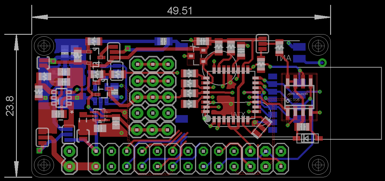
I hope it will be finished routing this week end. I will have optimizations to do but most difficult is done. Now I am routing the MYSX connector. @Anticimex or someone else, if you have time, could you tell me if my MYSX is right please?1:VIN 2:VCC3 3:VCCIO 4:gnd 5:tx 6:rx 7:a6 8:a7 9:d2 10:d3 11:d5 12:d6 13:scl 14:sda 15:d7 16:d8 17:mosi 18:miso 19:sck 20:d10Same specs as my prev rev. This version will be better than my previous I think as I have 4layer I can make better and smarter plane (and keep a plane dedicated to gnd). cool . I have added a regulator too. So now I can choose vin_bat/3v dc booster/3v reg 16v max. Jumpers are now smd.
On screenshot, boosters and low power stuff is on the left. in the middle 3 external i2c, rfm and nrf smd are on bottom. Downward are BAT connector, MYSXconnector, AVRSPI.
It is small and if you use nrf it will be a little more higher (maybe 1cm as you can see). maybe I will try to find a little name for fun, MyTinyCamel??? :smiley:
and it is still 0805, so solderable for me. cool! -
Hi guys!
Last night I had a long run thinking how to make my proto rev2. Here is how it looks for the moment.
I hope it will be finished routing this week end. I will have optimizations to do but most difficult is done. Now I am routing the MYSX connector. @Anticimex or someone else, if you have time, could you tell me if my MYSX is right please?1:VIN 2:VCC3 3:VCCIO 4:gnd 5:tx 6:rx 7:a6 8:a7 9:d2 10:d3 11:d5 12:d6 13:scl 14:sda 15:d7 16:d8 17:mosi 18:miso 19:sck 20:d10Same specs as my prev rev. This version will be better than my previous I think as I have 4layer I can make better and smarter plane (and keep a plane dedicated to gnd). cool . I have added a regulator too. So now I can choose vin_bat/3v dc booster/3v reg 16v max. Jumpers are now smd.
On screenshot, boosters and low power stuff is on the left. in the middle 3 external i2c, rfm and nrf smd are on bottom. Downward are BAT connector, MYSXconnector, AVRSPI.
It is small and if you use nrf it will be a little more higher (maybe 1cm as you can see). maybe I will try to find a little name for fun, MyTinyCamel??? :smiley:
and it is still 0805, so solderable for me. cool!@scalz looks good. Almost identical to my routing for MYSX :)
One thing; consider using something different than d10 for SPI CS as I believe most boards uses that pin for radio SPI CS. It would still work of course but you'll end up with a non-default radio configuration. -
@Anticimex. cool. thx. for d10 ok. so in fact pin20 is an external cs pin. I thought it was just atmel rerouting so I rerouted radio cs pin. I am too dumb sometimes! Ok I will look at this tonight. Oh, and I can share my files with you if you are curious. For the moment it is not on my git. I am waiting to be sure..
See you soon. -
@Anticimex. cool. thx. for d10 ok. so in fact pin20 is an external cs pin. I thought it was just atmel rerouting so I rerouted radio cs pin. I am too dumb sometimes! Ok I will look at this tonight. Oh, and I can share my files with you if you are curious. For the moment it is not on my git. I am waiting to be sure..
See you soon.@scalz Correct. The purpose of MYSX_D14_CS is to provide a CS for one SPI slave on the daughterboard (it also doubles as a digital IO called D14). Any digital IO could be used for this but by having a dedicated pin that at least can serve as SPI CS, daughterboards with one SPI device can assume this pin can be used for CS.
-
just for share. as I am happy.. finally it's all routed, it was some work! maybe I will add an optional led. some check to improve it and I will test dirty or elecrow. I don't know yet..
I modified my pinout for MYSX too.
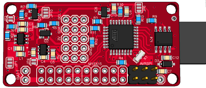
I like how it looks with rfm69 :smiley:
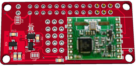
not bad with nrf smd too
-
Nice and compact :)
-
thx :smile:
I added a led on sck (like on pro mini). not sure if it is the best pin (dualoptiboot use default D9 if I remember right). I will see. I am improving silkscreen, some vias and some trace now. and need to add a small osh logo. I think I will be able to order it next week. Can't wait to see this tiny camel :smiley:
I am feeling holes are big but it is 3.2mm. maybe I should use 2.2mm but it is small.
on MYSX, now pin15=A0, pin20=D7. -
@Anticimex: thx. your schematics looks very good. I am not so skilled :smiley: I missed one or two decoupling capa I think. I will add those and upload my schem this afternoon to show you.
by sharing we can do so better things:wink: -
@Anticimex: thx. your schematics looks very good. I am not so skilled :smiley: I missed one or two decoupling capa I think. I will add those and upload my schem this afternoon to show you.
by sharing we can do so better things:wink:@scalz Practice makes perfect :) What license do you plan to use for your board? Same as me or have you found another OSHW licence that is simpler? I find some aspects of the one I have chosen that I am not too happy with, but I have not found a better one.
-
@Anticimex: actually I am not very familiar with the license system. I have not taken the time to look at the differences. osh or cc-by-nc-sa??? I need to check what it involves. so for the moment I just paste osh logo to tell it is open source. What aspects don't you like about CERN for example?
-
@Anticimex: actually I am not very familiar with the license system. I have not taken the time to look at the differences. osh or cc-by-nc-sa??? I need to check what it involves. so for the moment I just paste osh logo to tell it is open source. What aspects don't you like about CERN for example?
@scalz Well, it is a bit cumbersome since it require quite a few documents to be included with the product in question. And it stipulates that this documentation should be copied and maintained by anyone basing their work on said product (so I could go after you if I was a evil bastard ;) ) and for the record, I won't. Because I release my work freely, but I still think it is nice to have some formal document to govern the rights of the authour even if there is no money involved.
But I have not found any other license that makes this easier, and since I already ave inncluded the necessary documentation structure to my git, I don't have to worry about anything else than the changelog from now on, so I will probably stick with it. -
@Anticimex: ahahah! ok. What you are saying about CERN and its documentation is exactly what I don't like!!! I do this freely too, so I don't care about all this stuff but if it is needed I do it. and I am very glad each time to say who inspired me.
so you think I should stick to CERN? :smiley:
But I agree that copyright, licensing needs some rules for respect to the author. I helped my dad few years ago to get a patent. So I understand the problematic.
I think lots of innovation today are often improvement and mix of others existing good things. and then a patent.. -
@Anticimex: ahahah! ok. What you are saying about CERN and its documentation is exactly what I don't like!!! I do this freely too, so I don't care about all this stuff but if it is needed I do it. and I am very glad each time to say who inspired me.
so you think I should stick to CERN? :smiley:
But I agree that copyright, licensing needs some rules for respect to the author. I helped my dad few years ago to get a patent. So I understand the problematic.
I think lots of innovation today are often improvement and mix of others existing good things. and then a patent..@scalz I think my personal stand on this is that I will stick to CERN OHL myself. I do not require anyone to keep CERN OHL even if they copy parts of my work even if the OHL require it (my design, I make my own rules on what I enforce, nobody else will do it for me anyway :) ).
I just think it is good to have some form of "common" license platform that anyone can use or read that formally grants permissions. I am more interested in the "rights" than the "requierds". To me, the license shows everyone that I am formally granting free use of the design. I will of course not discourage anyone from following the formal CERN OHL rules for copying OHL licensed work, but I won't hunt anyone for it. A simple reference to my board in a changelog or similar is plenty! If you worry about the licence, I can also supply a GPG signed statement you could add to a commit where I relieve the licence requirement in case you want to get rid of the CERN stuff "legally". I am not sure it is "legal" for me to do it, but since it is my design in question, I feel I have the right to do any permission I want. And the signature would tell anyone that it really was me giving the permission. But I cannot see why anybody would really care.