Sensor board with booster and supervisor
-
Hi!
one of my needs is sort of generic node with ultra low power and power management options.
So I started to design my own board. And during my research I have found two different boards which focused my attention.- one design Anticimex started and shared (I felt in love with some ideas : power rails and jumpers).
- and ulpnode work https://hallard.me/ulpnode-low-power-secret/, not released yet, but soon I think. Very great idea too!
First, Anticimex and Charles (ulpnode), thank you very much for your share. You have inspired me!
Now, I am trying to make these two boards in one.
So here is the schematic, and an overview of what it will look. All is opensource. It is still in dev, so for the moment it is not recommanded to use files (available on my git).An overview:
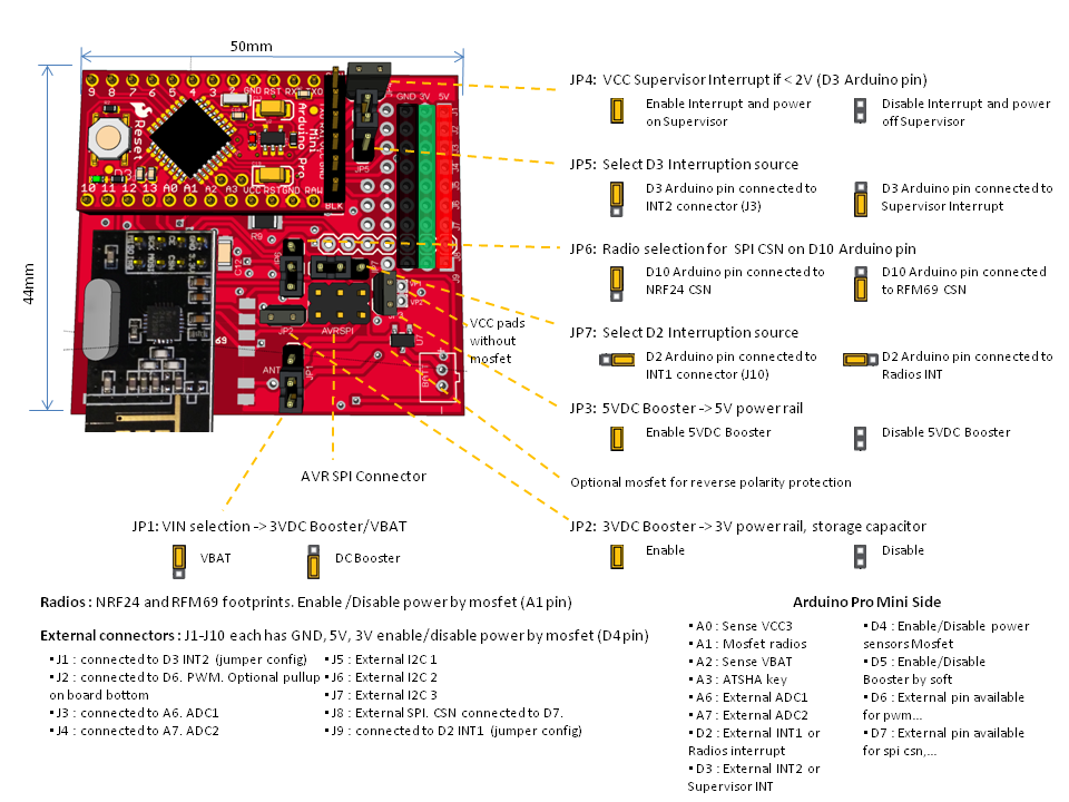
I have made two versions : nrf_dip/rfm69, nrf_smd/rfm69, I removed all trace and gnd plane under nrf antenna to be sure there will be no problem.
The idea for ultra low power:having the lowest consumption in sleep mode require to disable bod and watchdog. Watchdog needs near 20ua maybe. So we can't use it for waking up.
So, how can we wake it up after a period? With pin change interrupt. The idea is to get a storage capa full, then go to sleep. Supervisor voltage, which is powered by vin, will monitor vcc capa discharge and will enable pin change interrupt at 2V level. At this moment, supervisor is enabling dcboost but for a time. So we need to maintain it by an output of arduino. And we do all the wake up stuff if needed and process sensors, messages....
If nothing needed, we increment counter. As we can know the discharge time from the storage capa we know how many cycles are needed.Why I choosed Arduino mini instead atmel chip is because : the board can be smaller like this, and I was lazy to reroute atmel. Few small ics, others are 1206.
Todo :
- check all routing : in progress
- test of different sleep mode: in progress
- if needed, modify bootloader to toggle some pin at startup (to enable dc booster, as supervisor will do it at startup, we must maintain pin level next) : in progress
Thanks for feedback
-
Hi.
Sorry for delay.
I am waiting for boards to test it. It will be easier to test as mcp1640 is too small to breadboard for me! I am waiting for uCurrent pcb too.
When I'll have news, I'll post it of course. -
Hi,
just wanted to share my work in progress. So I updated my first post. You can see an overview (I still need to make some cleanings).
And I would like to ask a question to grandmasters of electronics here, lol, as I have a little problem.Before, just little results, as I am still in the beginning of debugging the board and am happy with what I am seeing. I have not tried dc boosters and supervisors yet. I am actually testing mosfets and sensors. Here my setup for the moment:
- Ucurrent Gold (homemade, but calibration checked with some res)
- arduino with reg and led removed
- power directly from 2x1.5v battery
- mosfet on my schem are not the right ref. I had problems with them : arduino resets at startup. very strange. I changed the diode by 120o res. in case. but same problems. I changed mosfet by BS250 TO92 and it works. I need to figure what was happening.
- Sketch Mysensors, lib 1.4, BH1750. I get between 200-300nA in sleep mode. Wow am I dreaming???
There is lots of tricks I think, if you want to have low power. I will explain more when all will be ok. My problem actually is:
- Sketch starts. I read BH1750 : all is ok.
- Before sleep mode, I power off BH1750 by mosfet. Then I set SDA, SCL output=0 (if I don't do this I have hundred uA consumption). With output=0, I get 220nA
- I wake up from pin interrupt, then power mosfet, wait 10sec to be sure, bh1750.init, but sensor returns 0 value!!!
- In other hand, I have no problems with the radios.
- If I press reset button, my startup reading is ok. I have a problem to restore i2c bus I think. I don't understand as I was wondering BH1750.begin calls Wire.begin which should set registers???
Have you an idea about this??? Do you have some i2c init routine? I will dig in datasheet but in case you know what mistake I am doing
-
Hi,
just wanted to share my work in progress. So I updated my first post. You can see an overview (I still need to make some cleanings).
And I would like to ask a question to grandmasters of electronics here, lol, as I have a little problem.Before, just little results, as I am still in the beginning of debugging the board and am happy with what I am seeing. I have not tried dc boosters and supervisors yet. I am actually testing mosfets and sensors. Here my setup for the moment:
- Ucurrent Gold (homemade, but calibration checked with some res)
- arduino with reg and led removed
- power directly from 2x1.5v battery
- mosfet on my schem are not the right ref. I had problems with them : arduino resets at startup. very strange. I changed the diode by 120o res. in case. but same problems. I changed mosfet by BS250 TO92 and it works. I need to figure what was happening.
- Sketch Mysensors, lib 1.4, BH1750. I get between 200-300nA in sleep mode. Wow am I dreaming???
There is lots of tricks I think, if you want to have low power. I will explain more when all will be ok. My problem actually is:
- Sketch starts. I read BH1750 : all is ok.
- Before sleep mode, I power off BH1750 by mosfet. Then I set SDA, SCL output=0 (if I don't do this I have hundred uA consumption). With output=0, I get 220nA
- I wake up from pin interrupt, then power mosfet, wait 10sec to be sure, bh1750.init, but sensor returns 0 value!!!
- In other hand, I have no problems with the radios.
- If I press reset button, my startup reading is ok. I have a problem to restore i2c bus I think. I don't understand as I was wondering BH1750.begin calls Wire.begin which should set registers???
Have you an idea about this??? Do you have some i2c init routine? I will dig in datasheet but in case you know what mistake I am doing
@scalz Can you post the sketch? It might help in finding what is wrong.
-
@Moshe Livne: thank you. I found my mistake last night (Charles from ulpnode helped me). I needed to stop i2c bus and restore it after woken up in a precise way. I need to clean my code.I will post a sketch soon.
-
Hi.
As I am waiting for pcb, I am trying to miniaturize my board. It will be full smd (0805) and smaller size. And 4layers. So if use atmel 328p instead of arduino pro mini clone, I will have less chance to get a bad arduino clone.
Here what I am trying to do. It is 49x23, so I hope to be able to put two boards on a 50x50 to reduce cost.
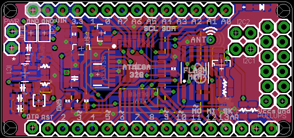
All described in my first post is integrated except 5v dc booster and one i2c (but is exposed on border, so there is 3 i2cs).
Lazy, I firstly took the moteino and added signing. then i enlarged the board to fit what I need. But I think I will not be able to fit the 5v booster. no enough place for footprint for the moment.But it is very experimental to see if it fits and it is doable. So now, I don't like the design, it is not beautiful I think and it should be better. I will make a new try from scratch this time. So here my question, if @Anticimex or @tbowmo have some recommandations, I would be very happy:
- do you think MYSConnector would be preferable than how it is? I already imagine your answer ahaha! When you decided the pinout what was your basis? do you have something with atmel rooted to the MYSXconnector 1.5?
- so if I understand right your connector, I need to make the two row, one connector.
- could you show me a screenshot of MYSX1.5 with labels. To be sure...
- as I am using booster, but with a large capa, do you have some recommandations about 4layer trace route? My first 4layer attempt so, I have read lots of articles about this, but if you have good advices...
- finally, I think it will be difficult to have nrf smd and rfm because on the left I will have dc booster and don't want to interfere with nrf, and right I will need some external connectors or additional i2c, power...
See you soon.
Ah, and I know it is Eagle. No time to learn Kicad for the moment. But maybe it will be exportable to kicad next.
-
Hi.
As I am waiting for pcb, I am trying to miniaturize my board. It will be full smd (0805) and smaller size. And 4layers. So if use atmel 328p instead of arduino pro mini clone, I will have less chance to get a bad arduino clone.
Here what I am trying to do. It is 49x23, so I hope to be able to put two boards on a 50x50 to reduce cost.
All described in my first post is integrated except 5v dc booster and one i2c (but is exposed on border, so there is 3 i2cs).
Lazy, I firstly took the moteino and added signing. then i enlarged the board to fit what I need. But I think I will not be able to fit the 5v booster. no enough place for footprint for the moment.But it is very experimental to see if it fits and it is doable. So now, I don't like the design, it is not beautiful I think and it should be better. I will make a new try from scratch this time. So here my question, if @Anticimex or @tbowmo have some recommandations, I would be very happy:
- do you think MYSConnector would be preferable than how it is? I already imagine your answer ahaha! When you decided the pinout what was your basis? do you have something with atmel rooted to the MYSXconnector 1.5?
- so if I understand right your connector, I need to make the two row, one connector.
- could you show me a screenshot of MYSX1.5 with labels. To be sure...
- as I am using booster, but with a large capa, do you have some recommandations about 4layer trace route? My first 4layer attempt so, I have read lots of articles about this, but if you have good advices...
- finally, I think it will be difficult to have nrf smd and rfm because on the left I will have dc booster and don't want to interfere with nrf, and right I will need some external connectors or additional i2c, power...
See you soon.
Ah, and I know it is Eagle. No time to learn Kicad for the moment. But maybe it will be exportable to kicad next.
@scalz
I will publish my revised sensor motherboard on the forum this week. It has MYSX 1.5.
Depending on forum feedback, this board might (or might not) evolve to a "official" MySensors board.
The MYSX specification is available here: https://github.com/mysensors-kicad/documentation/blob/master/TheMYSXconnector.pdf
And it comes in various versions to accomodate different types of boards.
My board will also come in various versions. For two different cases and a low-cost 5x5cm edition (from DirtyPCBs).
It is the "second generation" board compared to the board I did which you took inspiration from. But as you know, my first version had a few bugs, which I have resolved but yet not published.
I hope to be able to at least write a forum topic and list the board features this week. -
@Anticimex: thank you very much for your reply. So do you think I don't need to spend more time on this board, even if it is ulpnode like, and I would make it smaller (50x23 with MYSX) ?
I looked at MYSXconnector. Just two questions, then I will wait for your great work!- 20pins ok. but is it first 10 pins on first row? Maybe dumb question as I think it is group of 4x2. So 9-12 first row, and 13-16 scond row, 17-20 first row...
- On MYSX 1.3, I am little confused, pin13 SCL, pin14 SDA but pin 16 is A4???
If what I am trying to do is still actual, I will convert it to Kicad next as I saw it is possible to import eagle project. Just want to share, not compete, I don't care about this.
Anyway, I can't wait to see your board, I'm a big fan of Mysensors Team work :smiley:
-
@Anticimex: thank you very much for your reply. So do you think I don't need to spend more time on this board, even if it is ulpnode like, and I would make it smaller (50x23 with MYSX) ?
I looked at MYSXconnector. Just two questions, then I will wait for your great work!- 20pins ok. but is it first 10 pins on first row? Maybe dumb question as I think it is group of 4x2. So 9-12 first row, and 13-16 scond row, 17-20 first row...
- On MYSX 1.3, I am little confused, pin13 SCL, pin14 SDA but pin 16 is A4???
If what I am trying to do is still actual, I will convert it to Kicad next as I saw it is possible to import eagle project. Just want to share, not compete, I don't care about this.
Anyway, I can't wait to see your board, I'm a big fan of Mysensors Team work :smiley:
@scalz i am sure our boards will complement each other's. It is not my intention either to "replace" your board in any way.
About the connector, this is not clear from the specification, but the pinout is crossing. So odd numbers on one side and even on the other. For kicad users we have MySensors specific libraries where symbols and footprints are available but the spec should be updated to Nä clarify this. Thanks for pointing this out.
About the signal naming, they are not to be confused with Arduino pin naming. The names are MYSX specific and not to be confused with Arduino at all. So A4 on MYSX has nothing to do with A4 on an Arduino board.
In the future, "offical" boards which have MYSX will have a board header in some form that maps the MYSX names to the Arduino pin it's connected to on that particular board. We are busy in the "core team" discussing how to manage this so it will be easy for everybody to use and to make their own designs. -
@Anticimex: ok. I was not thinking about odd/even. it is clear to me now thx.
Maybe this evening I will try to follow your Github Kicad tuto, so I can see correspondance for digital pins and cs pin on connector symbol as I am not sure.
But I'm not ready to use Kicad ahaha! I would have to re-do my learning curve!! and it took me so long time to be friendly with Eagle, and I discover new things every week...I understand MYSX concept and I agree, harmonization will be useful for projects.
And thx for your kindness, it encourages me:smiley:
-
This post is deleted!
-
Hi guys!
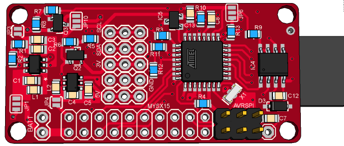
Last night I had a long run thinking how to make my proto rev2. Here is how it looks for the moment.
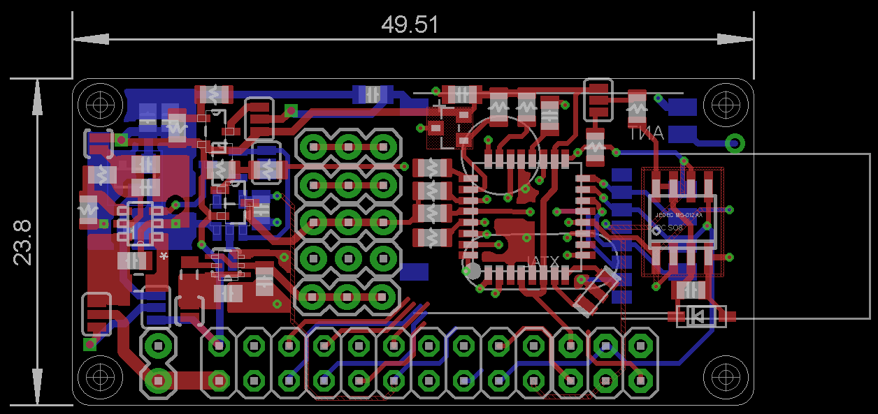
I hope it will be finished routing this week end. I will have optimizations to do but most difficult is done. Now I am routing the MYSX connector. @Anticimex or someone else, if you have time, could you tell me if my MYSX is right please?1:VIN 2:VCC3 3:VCCIO 4:gnd 5:tx 6:rx 7:a6 8:a7 9:d2 10:d3 11:d5 12:d6 13:scl 14:sda 15:d7 16:d8 17:mosi 18:miso 19:sck 20:d10Same specs as my prev rev. This version will be better than my previous I think as I have 4layer I can make better and smarter plane (and keep a plane dedicated to gnd). cool . I have added a regulator too. So now I can choose vin_bat/3v dc booster/3v reg 16v max. Jumpers are now smd.
On screenshot, boosters and low power stuff is on the left. in the middle 3 external i2c, rfm and nrf smd are on bottom. Downward are BAT connector, MYSXconnector, AVRSPI.
It is small and if you use nrf it will be a little more higher (maybe 1cm as you can see). maybe I will try to find a little name for fun, MyTinyCamel??? :smiley:
and it is still 0805, so solderable for me. cool! -
Hi guys!
Last night I had a long run thinking how to make my proto rev2. Here is how it looks for the moment.
I hope it will be finished routing this week end. I will have optimizations to do but most difficult is done. Now I am routing the MYSX connector. @Anticimex or someone else, if you have time, could you tell me if my MYSX is right please?1:VIN 2:VCC3 3:VCCIO 4:gnd 5:tx 6:rx 7:a6 8:a7 9:d2 10:d3 11:d5 12:d6 13:scl 14:sda 15:d7 16:d8 17:mosi 18:miso 19:sck 20:d10Same specs as my prev rev. This version will be better than my previous I think as I have 4layer I can make better and smarter plane (and keep a plane dedicated to gnd). cool . I have added a regulator too. So now I can choose vin_bat/3v dc booster/3v reg 16v max. Jumpers are now smd.
On screenshot, boosters and low power stuff is on the left. in the middle 3 external i2c, rfm and nrf smd are on bottom. Downward are BAT connector, MYSXconnector, AVRSPI.
It is small and if you use nrf it will be a little more higher (maybe 1cm as you can see). maybe I will try to find a little name for fun, MyTinyCamel??? :smiley:
and it is still 0805, so solderable for me. cool!@scalz looks good. Almost identical to my routing for MYSX :)
One thing; consider using something different than d10 for SPI CS as I believe most boards uses that pin for radio SPI CS. It would still work of course but you'll end up with a non-default radio configuration. -
@Anticimex. cool. thx. for d10 ok. so in fact pin20 is an external cs pin. I thought it was just atmel rerouting so I rerouted radio cs pin. I am too dumb sometimes! Ok I will look at this tonight. Oh, and I can share my files with you if you are curious. For the moment it is not on my git. I am waiting to be sure..
See you soon. -
@Anticimex. cool. thx. for d10 ok. so in fact pin20 is an external cs pin. I thought it was just atmel rerouting so I rerouted radio cs pin. I am too dumb sometimes! Ok I will look at this tonight. Oh, and I can share my files with you if you are curious. For the moment it is not on my git. I am waiting to be sure..
See you soon.@scalz Correct. The purpose of MYSX_D14_CS is to provide a CS for one SPI slave on the daughterboard (it also doubles as a digital IO called D14). Any digital IO could be used for this but by having a dedicated pin that at least can serve as SPI CS, daughterboards with one SPI device can assume this pin can be used for CS.
-
just for share. as I am happy.. finally it's all routed, it was some work! maybe I will add an optional led. some check to improve it and I will test dirty or elecrow. I don't know yet..
I modified my pinout for MYSX too.
I like how it looks with rfm69 :smiley:
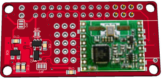
not bad with nrf smd too
-
Nice and compact :)
-
thx :smile:
I added a led on sck (like on pro mini). not sure if it is the best pin (dualoptiboot use default D9 if I remember right). I will see. I am improving silkscreen, some vias and some trace now. and need to add a small osh logo. I think I will be able to order it next week. Can't wait to see this tiny camel :smiley:
I am feeling holes are big but it is 3.2mm. maybe I should use 2.2mm but it is small.
on MYSX, now pin15=A0, pin20=D7. -
thx :smile:
I added a led on sck (like on pro mini). not sure if it is the best pin (dualoptiboot use default D9 if I remember right). I will see. I am improving silkscreen, some vias and some trace now. and need to add a small osh logo. I think I will be able to order it next week. Can't wait to see this tiny camel :smiley:
I am feeling holes are big but it is 3.2mm. maybe I should use 2.2mm but it is small.
on MYSX, now pin15=A0, pin20=D7.
Hello! It looks like you're interested in this conversation, but you don't have an account yet.
Getting fed up of having to scroll through the same posts each visit? When you register for an account, you'll always come back to exactly where you were before, and choose to be notified of new replies (either via email, or push notification). You'll also be able to save bookmarks and upvote posts to show your appreciation to other community members.
With your input, this post could be even better 💗
Register Login