Battery Sensor with stepup and on/off transistor
-
i have only a test setup at the moment with 2 AAA batteries. So i cant give you a battery lifetime :/
I use a arduino 3.3v and the stepup pushes the voltage to 5v for the DHT.
@n3ro said:
i have only a test setup at the moment with 2 AAA batteries. So i cant give you a battery lifetime :/
I use a arduino 3.3v and the stepup pushes the voltage to 5v for the DHT.
can you tell me why u push the voltage to 5v? the dht works great with 3.3v
-
@n3ro said:
i have only a test setup at the moment with 2 AAA batteries. So i cant give you a battery lifetime :/
I use a arduino 3.3v and the stepup pushes the voltage to 5v for the DHT.
can you tell me why u push the voltage to 5v? the dht works great with 3.3v
-
Ok,
is it possible to supply the arduino, NRF and DHT directly from an 3,7V LiPo? Your 2N2222A as an Switch for the DHT Power Pin? Can you tell me, what is the current consumption of NRF, and Arduino during Sleep mode by code "gw.sleep" -
Ok,
is it possible to supply the arduino, NRF and DHT directly from an 3,7V LiPo? Your 2N2222A as an Switch for the DHT Power Pin? Can you tell me, what is the current consumption of NRF, and Arduino during Sleep mode by code "gw.sleep"@ht81
hmm the max voltage of the NRF is 3.6v (https://www.sparkfun.com/datasheets/Components/SMD/nRF24L01Pluss_Preliminary_Product_Specification_v1_0.pdf)
maybe the NRF is broker after 3.7v. i dont know...the 2N2222A turns the stepup on and off. the DHT is direct connected to the stepup.
you can read many stuff about the power consumption of NRF+Arduino in the forum. With modified fuses and cutted LED+power regulator ~40uA
-
@n3ro
I have been looking into making some battery powered sensors.
I have some questions about your setup, because I've been looking for some step up convertors but the 3.3v seems so expensive compared to the step up your using (I've only found this 3.3v one) which is 3+ times more expensive than this 5v one).Do you power your pro mini 3.3v from the 5v step up?
Did you remove the on board power regulator (I'm thinking you haven't)?
Does your DHT sensor work fine with 5v?I've been breaking my head over how to make the cheapest battery powered sensor possible, but it's been difficult since I'm very much still a noob.
-
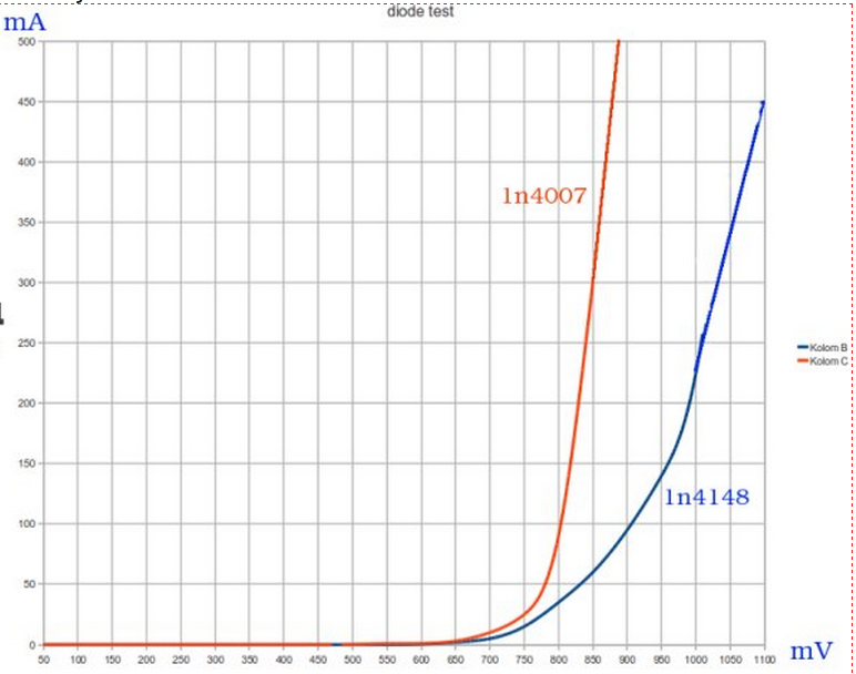
If one uses a LiPo battery giving (officially) 3.7V, it could be higher when it is new. I would suggest putting a Schottky diode (like 1N4001 of 1N4007) between positive of battery and VCC of NRF24. This way you force a voltage drop of minimal 0,5V and under load this goes up to 1V. The NRF24 works perfectly fine like this.
I have a setup where I feed the atmega328p and a SIM800L with 4V, the NRF24 gets around 3.4V at startup, and under load around 3.1V -
If one uses a LiPo battery giving (officially) 3.7V, it could be higher when it is new. I would suggest putting a Schottky diode (like 1N4001 of 1N4007) between positive of battery and VCC of NRF24. This way you force a voltage drop of minimal 0,5V and under load this goes up to 1V. The NRF24 works perfectly fine like this.
I have a setup where I feed the atmega328p and a SIM800L with 4V, the NRF24 gets around 3.4V at startup, and under load around 3.1V@GertSanders Sounds like a good (and cheap) way to get in the safe range for the radio when using a Lipo (rechargeable) cell. btw. 1N4001/7 is 'normal' (not Schottky)rectifier diode with ~0.7V drop. This would get the 4.1V (max lipi) to 3.4V. Did you try this with a stable radio performance?
-
@AWI: thanks for the rectification ;-). I built a SMS sensor, to see if I could control a relay both via SMS and via the MySensors network. It all needed to fit on a 50x50mm board, so using the diode was a space saving choice. Works very wel indeed.
I'm using the NRF24 with PA and LNA, so currents go up to 120-140mA. An 1N4001/7 is a bit overkill here, but it does not hurt to over-dimension in this case, and these diodes are cheap and available everywhere.Since I'm using a GSM module, I did not need to think about battery use, my setup needs mains power (I'm feeding a DC converter 12VDC, getting 4.1V). For battery based sensors, I'm thinking it could be applicable as well.
-
Anyone else but me that have heard an annoying audible noise from the 5V step-up? Somehow the quality of the 5V step-up seems a little worse from my experience (don't power the nRF via step-down from this). But, it still can't explain the incredibly high (and continuously increasing) price tag on the 3.3 V step-up, which is a mystery.
btw I think powering the sensors only as in this thread is really interesting. Even if it's not always economical due to start up time, it could be used for sensors active part time of day. E.g. I'm planning a battery powered PIR only active during night time and expect it to survive longer with a step-up compared to without.
-
@ht81 Hey, the NRF is directly connected to the battery. only the DHT use the stepup.
i use this stepup: http://www.banggood.com/2Pcs-500mA-DC-DC-1V-5V-Converter-Step-Up-Module-Power-Module-p-945167.html
Just put a transistor in front of the stepup. this is all :)
@n3ro Why would you need a step up for DHT, I am running DHT11 on 3.3v and it work fine.
-
@n3ro Why would you need a step up for DHT, I am running DHT11 on 3.3v and it work fine.
@Suresh-Mali My sensor node is powered with two AAA Batts. Over the time the voltage drops down to 1,9v.
The DHT only works with ~3v. so i need the stepup only to power the dht
i use this setup with my multisensor nodes.
http://forum.mysensors.org/topic/1514/multisensor_pir_dht_ldr_battery/3Without transistor the battery is drained in ~2 month (black line)
with transistors in ~10 month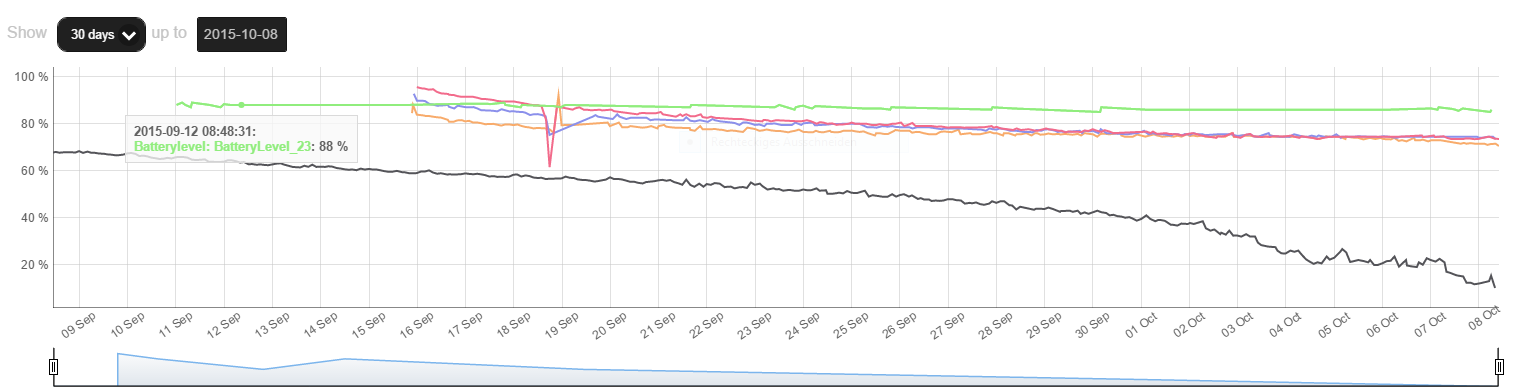
pimatic + MySensors + Homeduino + z-way
https://github.com/n3roGit/MySensors_n3ro -
@Suresh-Mali My sensor node is powered with two AAA Batts. Over the time the voltage drops down to 1,9v.
The DHT only works with ~3v. so i need the stepup only to power the dht
i use this setup with my multisensor nodes.
http://forum.mysensors.org/topic/1514/multisensor_pir_dht_ldr_battery/3Without transistor the battery is drained in ~2 month (black line)
with transistors in ~10 month@n3ro Gr8, makes sense.:+1:
-
Hey togehter,
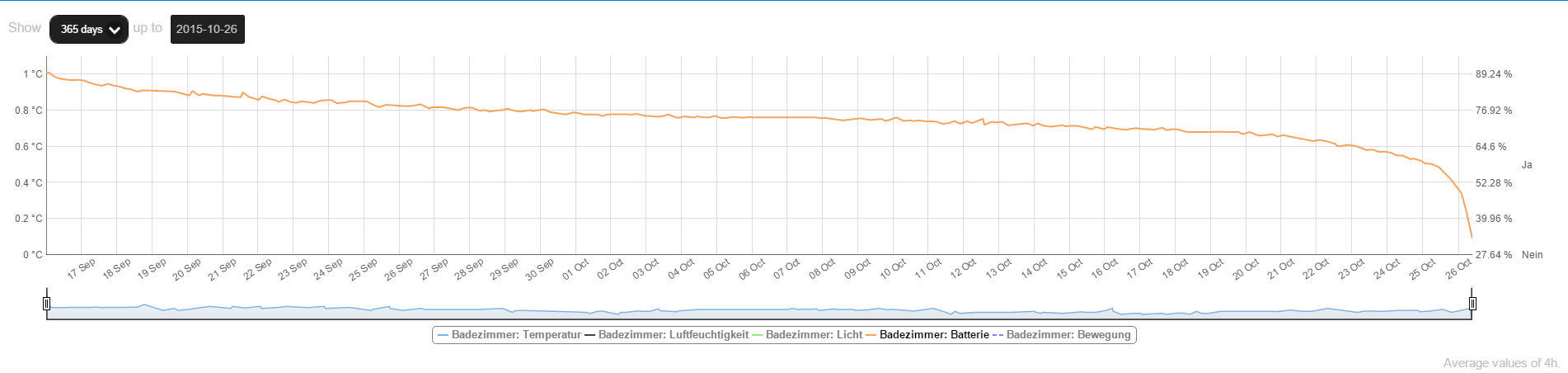
is a battery drain graph like this normal with alkaline batteries?
regards,
n3ro@n3ro said:
is a battery drain graph like this normal with alkaline batteries?
If you mean the sudden drop at the end, the answer is yes. This is called a S curve because it looks like a (very stretched) S. That's the typical behavior of most batteries.
-
The fact that you drain the battery in less then 2 months is probably due to the presence detection. I'm assumung this is using passive IR and is always on ? As mentioned by @mfalkvidd the shape is normal.
I use the breakout for SI7021 from Aliexpress and these use very little current. Also, there is no need for a step up, as this sensor works down to 1.8V. For light detection I use a LDR and 1MOhm resistor combination connected to a digital pin for power and analog pin for measuring. Works nicely because I let it settle (I first call the SI7021 to get the temperature and check the battery voltage, then I measure the analog value of the LDR. I only need relative values for light, so LDR is more then accurate enough for me. -
The fact that you drain the battery in less then 2 months is probably due to the presence detection. I'm assumung this is using passive IR and is always on ? As mentioned by @mfalkvidd the shape is normal.
I use the breakout for SI7021 from Aliexpress and these use very little current. Also, there is no need for a step up, as this sensor works down to 1.8V. For light detection I use a LDR and 1MOhm resistor combination connected to a digital pin for power and analog pin for measuring. Works nicely because I let it settle (I first call the SI7021 to get the temperature and check the battery voltage, then I measure the analog value of the LDR. I only need relative values for light, so LDR is more then accurate enough for me.@GertSanders
thx :)I have just ordered some SI7021 for testing.
My Pir sensors are these ones:
http://www.amazon.de/gp/product/B008EGH3FM50 Mikroampere
i dont know if this is aktive or passiv :-/
regards,
n3ro -
It's a passive IR module, and using 50uA, which is about 5 times the average consumption of my temperature/humidity sensors (between 8 and 11 uA depending on the amount of message resends needed).
The nice thing about the module you use is the low voltage it needs to work (0.8V <-> 9V).
-
It's a passive IR module, and using 50uA, which is about 5 times the average consumption of my temperature/humidity sensors (between 8 and 11 uA depending on the amount of message resends needed).
The nice thing about the module you use is the low voltage it needs to work (0.8V <-> 9V).
-
@GertSanders said:
(0.8V <-> 9V)
Yes. I had a few problems with the 5v PIRs. That's why I ordered this.
Hello! It looks like you're interested in this conversation, but you don't have an account yet.
Getting fed up of having to scroll through the same posts each visit? When you register for an account, you'll always come back to exactly where you were before, and choose to be notified of new replies (either via email, or push notification). You'll also be able to save bookmarks and upvote posts to show your appreciation to other community members.
With your input, this post could be even better 💗
Register Login