Rebuild of my broken 433mhz Cresta/hideki UV-Sensor
-
Hello,
I just started with arduino and mysensors and I would like to share my first steps (re)building my broken uv-sensor.
I bought the orignal TS704 UV sensor about two years ago. A few weeks ago it stopped sending acurate UV readings. On lots of placesa on the internet there are complaints abouts this sensor and the relative short lifetime. Main reason I think is water leakage in the sensor. I didn't want to buy a new one because the problem would be back within 2 years and they are realy expensive at the moment (about €70).
Then I found the mysensors site in my quest to fix my broken device and my first sensor project was born!
I ordered the pieces I needed and started to build.
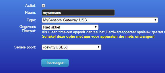
First the gateway, connected to domoticz which was easy as I connected it directly to the raspberry pi using the pigatewayserial software. Antenna directly connected to the Pi so no Arduino board needed!.
Changed tty TTY_NAME := /dev/ttyMySensorsGateway to tty
TTY_NAME := /dev/ttyUSB30 in the makefile because Domoticz cannot use ttyMySensorsGateway.
After that It was easy to add the serialgateway to Domoticz!my list:
Arduino pro mini 8mb 3v
UVM-30a UV sensor
NRF24L01+ 2.4GHz Wireless Transceiver
TS704 UV sensor housing including 2xAA batery compartment
Used the default sketch with pin A0 instead of pin 3 (http://www.mysensors.org/build/uv)On my breadboard I had things up and running quite easy but the readings were strange. Even at night there was UV light measured. The problem was a mismatch between the intructions on this website about the out pin to use and the one mentioned in the sketch. Sketch showed pin A0 as OUT but website showed pin 3 as OUT.
@hek has confirmed that A0 is the correct pin. Website will be updated. (is updated now)
I was mislead because with nothing connected to pin A0 it still gives you output data.
It's also possible to use 3V for the UVM-30A instead of only 5volt I found this in the spec sheet.So the stepup from 3 to 5v is not needed I think?
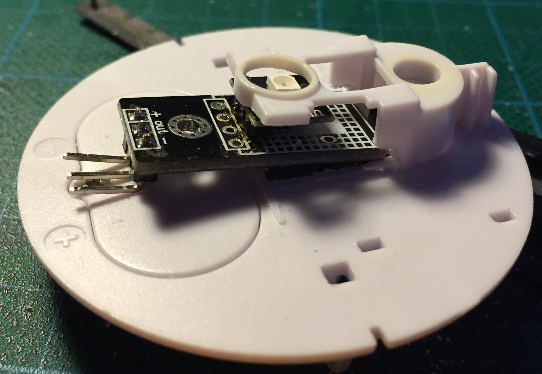
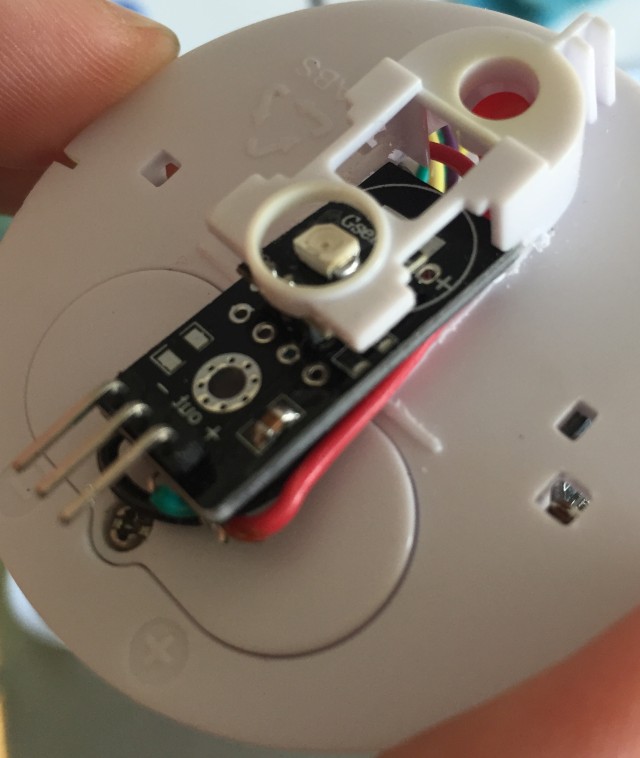
To get things in the housing I had to desolder the main piece from the UV sensor. Things have gone wrong from here because after that the sensor did not work anymore. Probably fried the sensor?! New one is on its way.
So I must think of another way to get the sensor in place at the top of the housing. There not enough place so I must be creative and not destroying another sensor!I also would like to share a short piece of code I found to test the uv sensors output. This way you don't need to attach all the radio wires to see if the sensor is working.
/*
This Sample code is for testing the UV Sensor .
#Connection:
VCC-5V
GND-GND
OUT-Analog pin 0
*/void setup()
{
Serial.begin(9600);// open serial port, set the baud rate to 9600 bps
}
void loop()
{
int sensorValue;
sensorValue = analogRead(0);//connect UV sensors to Analog 0
Serial.println(sensorValue);//print the value to serial
delay(200);
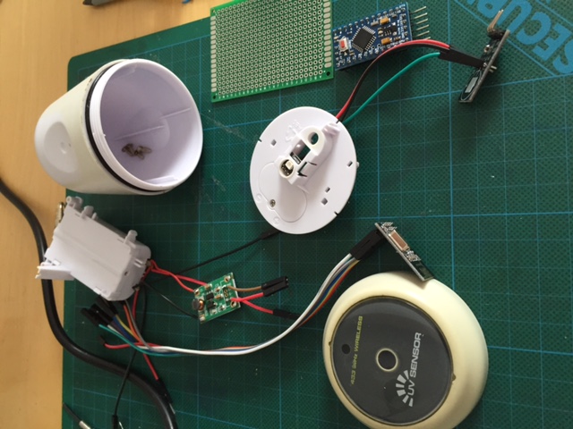
}The pieces on the table:
New sensor arrived and bought a 15W soldering iron.
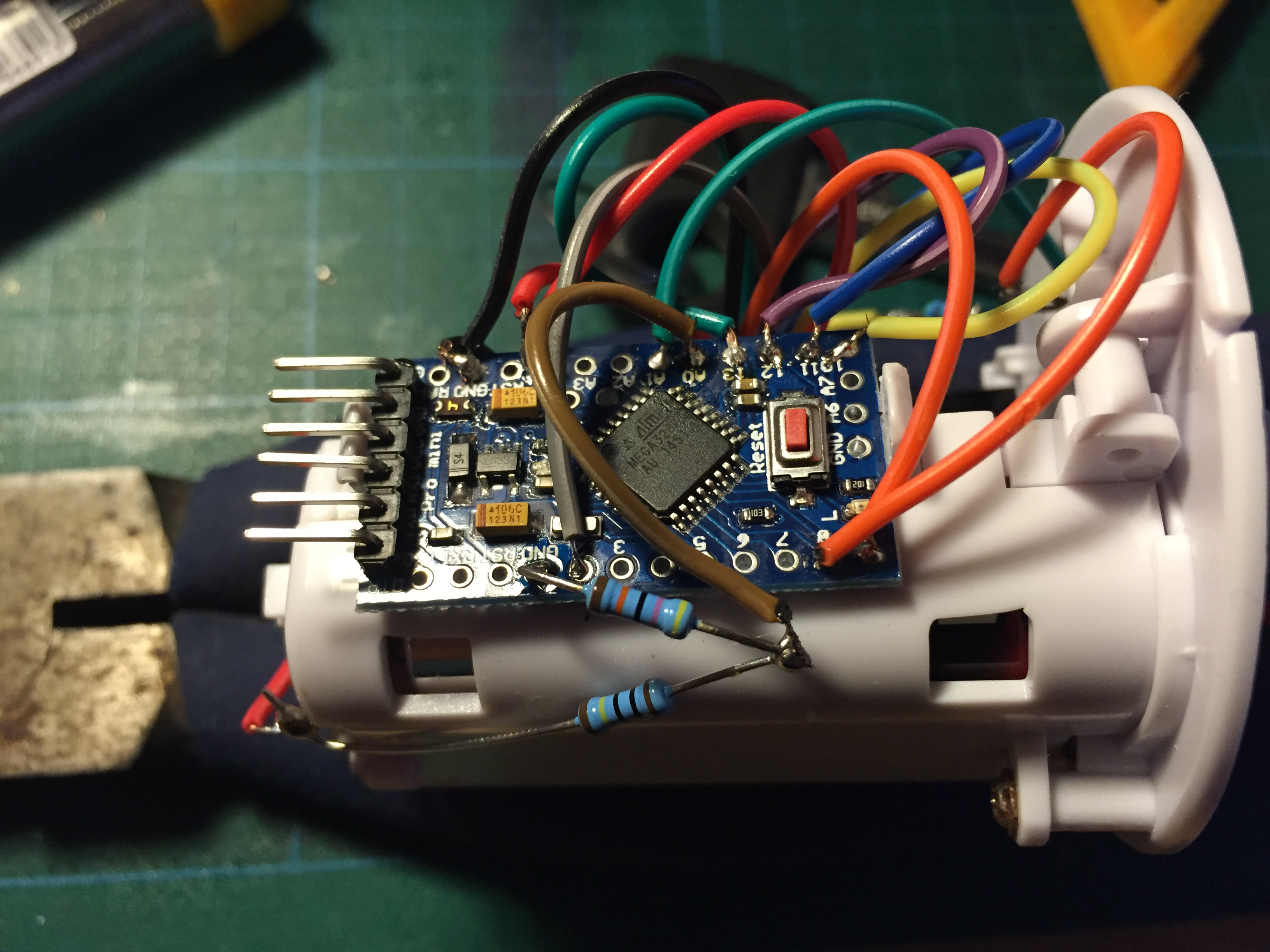
Puting things together and make some room for the sensor board
After everthing was put in place the sensor went outside for testing.
For reference I also used a nearby UV sensor via Weather Underground.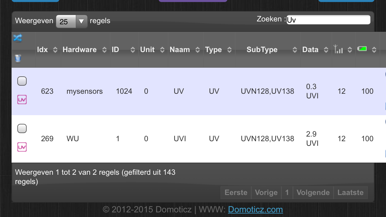
At first everything looked fine but it seems that the measurements from my sensor are to low.
I removed the sensor and did some testing with the above sketch to measure the output voltage on 3.3v and 5v but the results were the samen and to low.
Does anyone know what can cause this low measurement ? checked the wires. checked the sketch. replaced the arduino board.
Another broken sensor?Great post thanks for sharing!
I have also two of these which are not functioning anymore. Did you find a solution to the low values after all?
-
Nice one! Good to have in the summe here when the kids are outside... I will build one as well.
Thank you for sharing! -
I had plans to "MySensor" my Oregon scientific UV Index sensor when it fails ( It seems like it us quite common that they fail within 2 years ) but the darn thing just keeps working :sunglasses: been working for 5 years now...
-
Great post thanks for sharing!
I have also two of these which are not functioning anymore. Did you find a solution to the low values after all?
-
I dont think it's a Sensor issue, rather a sketch issue....
I bought 4 UV sensors, and also experiencing this.
It could be that we need to multiply the value we send by 10 ? Or we need to do some magic after the analogRead callFrom what i understand the analogRead returns a value between 0-1023
1023 stands for the maximum voltage that can be read on this pin, and equals VREF
[Source](5 volts (on 5V Arduino boards) or 3.3 volts (on 3.3V Arduino boards))
So if we use 3.3V on the arduino, then 1023 stands for 3.3VWe go back from the digital value (0-1023) to voltage with:
Sourceint sensorValue = analogRead(A0);
float voltage= sensorValue * (3.3 / 1023.0);The above sketch is using mV, so we need to multiple the voltage by 1000
float voltage= sensorValue * (3.3 / 1023.0) * 1000.0;
-
How is the UV sensor / electronic best protected from rain and weather?
Some sort of plastic lid? Or this will remove UV rays?I guess you want to point the sensor straight up where the rain comes from :)
-
I use a plastic case like:
http://www.aliexpress.com/item/Free-Shipping-115-90-55MM-Waterproof-Clear-Cover-Plastic-Electronic-Project-Box-Enclosure-Case/2025251375.htmlI now use the following code to read the uv value:
#define READ_SAMPLE_INTERVAL (50) //define how many samples you are going to take in normal operation #define READ_SAMPLE_TIMES (5) //define the time interal(in milisecond) between each samples in #define VREF 5.0f float last_UVIndex = 0; uint16_t uvIndexValue [12] = { 50, 227, 318, 408, 503, 606, 696, 795, 881, 976, 1079, 1170}; float UVRead() { int i; float rs=0; for (i=0;i<READ_SAMPLE_TIMES;i++) { rs += analogRead(UV_PIN); delay(READ_SAMPLE_INTERVAL); } rs = rs/READ_SAMPLE_TIMES; return rs; } float GetUVIndexFromVoltage(float voltage) { float UV=0; int i; for (i = 0; i < 12; i++) { if (voltage <= uvIndexValue[i]) { UV = float(i); break; } } //calculate 1 decimal if possible if (i>0) { float vRange=float(uvIndexValue[i]-uvIndexValue[i-1]); float vCalc=voltage-uvIndexValue[i-1]; UV+=(1.0f/vRange)*vCalc-1.0f; } return UV; } void sendUVIRMeasurements(bool force) { bool tx=force; float sensorValue = UVRead(); float voltage= sensorValue * (VREF / 1023.0f) * 1000.0f; //mV if (voltage>1170) voltage=1170; //Serial.print("UV Analog reading: "); //Serial.println(voltage,2); float UVIndex=GetUVIndexFromVoltage(voltage); float diffUV = abs(last_UVIndex - UVIndex); #ifdef MY_DEBUG Serial.print(F("diffUV :"));Serial.println(diffUV); #endif if (diffUV > 0.1) tx = true; if (!tx) return; Serial.print("UVI: "); Serial.println(UVIndex,2); last_UVIndex = UVIndex; Serial.print("UV: "); Serial.println(UVIndex, 2); // send(msgUV.set(UVIndex,2)); //Avarage raUV.addValue(UVIndex); send(msgUV.set(raUV.getAverage(),2)); } -
I use a plastic case like:
http://www.aliexpress.com/item/Free-Shipping-115-90-55MM-Waterproof-Clear-Cover-Plastic-Electronic-Project-Box-Enclosure-Case/2025251375.htmlI now use the following code to read the uv value:
#define READ_SAMPLE_INTERVAL (50) //define how many samples you are going to take in normal operation #define READ_SAMPLE_TIMES (5) //define the time interal(in milisecond) between each samples in #define VREF 5.0f float last_UVIndex = 0; uint16_t uvIndexValue [12] = { 50, 227, 318, 408, 503, 606, 696, 795, 881, 976, 1079, 1170}; float UVRead() { int i; float rs=0; for (i=0;i<READ_SAMPLE_TIMES;i++) { rs += analogRead(UV_PIN); delay(READ_SAMPLE_INTERVAL); } rs = rs/READ_SAMPLE_TIMES; return rs; } float GetUVIndexFromVoltage(float voltage) { float UV=0; int i; for (i = 0; i < 12; i++) { if (voltage <= uvIndexValue[i]) { UV = float(i); break; } } //calculate 1 decimal if possible if (i>0) { float vRange=float(uvIndexValue[i]-uvIndexValue[i-1]); float vCalc=voltage-uvIndexValue[i-1]; UV+=(1.0f/vRange)*vCalc-1.0f; } return UV; } void sendUVIRMeasurements(bool force) { bool tx=force; float sensorValue = UVRead(); float voltage= sensorValue * (VREF / 1023.0f) * 1000.0f; //mV if (voltage>1170) voltage=1170; //Serial.print("UV Analog reading: "); //Serial.println(voltage,2); float UVIndex=GetUVIndexFromVoltage(voltage); float diffUV = abs(last_UVIndex - UVIndex); #ifdef MY_DEBUG Serial.print(F("diffUV :"));Serial.println(diffUV); #endif if (diffUV > 0.1) tx = true; if (!tx) return; Serial.print("UVI: "); Serial.println(UVIndex,2); last_UVIndex = UVIndex; Serial.print("UV: "); Serial.println(UVIndex, 2); // send(msgUV.set(UVIndex,2)); //Avarage raUV.addValue(UVIndex); send(msgUV.set(raUV.getAverage(),2)); }@GizMoCuz Nice to see that my old post suddenly comes to live! Thanks for sharing your sketch. It was one of my first builds so it could be the sketch but I also had strange readings using the sample code.
Be cautious with the box you're using. Screws get rusty quick and water leakage will occur!
I have ordered a GYML8511-Uv-sensor-module to try but I will try the old sensor first with your script! -
@GizMoCuz - Thanks for your box link. I have ordered one!
@edweather - Ill post some pictures when im done to keep it alive here! -
My UV sensors is complete!
(I have not recieved any case yet - so using a electronic box and a plastic bag :+1: )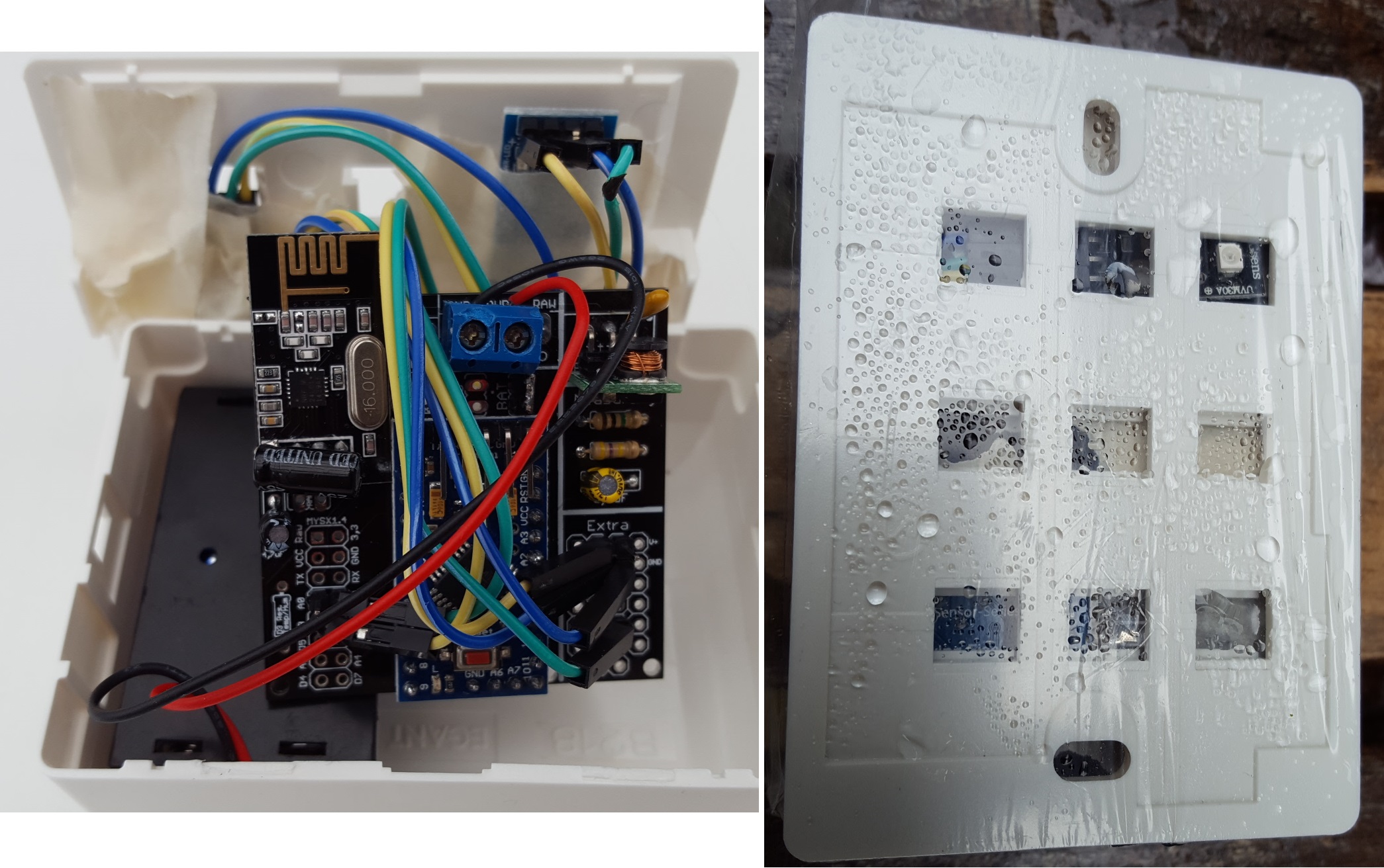
Its a dual UV and light sensor (LM393 Light Sensor), running om my EasyPCB and 2xAA batteries.
First I had some problems with power consumption about 1500uA. This was caused by the light sensor and i removed all leds and what I could with the digital part. My sollution was to power the light sensor from D3 and put it high and then low before sleep. Now im down to 60uA. Also had some interferance with my booster and that worked out great by adding a 0.1cap between out and gnd.
Having some issues with measuring batteries and analogread. There is a correct reading on the input on the atmega328 pin (about 0.9v) but still get -80% when using analogread. Must be a faulty atmega chip.
My code: (Combined of @GizMoCuz and MySensors)
Code removed - please use code below -
@GizMoCuz Nice to see that my old post suddenly comes to live! Thanks for sharing your sketch. It was one of my first builds so it could be the sketch but I also had strange readings using the sample code.
Be cautious with the box you're using. Screws get rusty quick and water leakage will occur!
I have ordered a GYML8511-Uv-sensor-module to try but I will try the old sensor first with your script!Trying to get the GYML8511 sensor working with the example code from sparkfun.
Must be me again but the thing gives me strange outputs.utput: 1023ML8511 output: 455 / ML8511 voltage: 1.47 / UV Intensity (mW/cm^2): 3.96
output: 1023ML8511 output: 688 / ML8511 voltage: 2.22 / UV Intensity (mW/cm^2): 10.19
output: 1023ML8511 output: 1023 / ML8511 voltage: 3.30 / UV Intensity (mW/cm^2): 19.14
output: 1023ML8511 output: 546 / ML8511 voltage: 1.76 / UV Intensity (mW/cm^2): 6.39
output: 1023ML8511 output: 568 / ML8511 voltage: 1.83 / UV Intensity (mW/cm^2): 6.98
output: 1023ML8511 output: 969 / ML8511 voltage: 3.13 / UV Intensity (mW/cm^2): 17.70
output: 1023ML8511 output: 842 / ML8511 voltage: 2.72 / UV Intensity (mW/cm^2): 14.30
output: 1023ML8511 output: 488 / ML8511 voltage: 1.57 / UV Intensity (mW/cm^2): 4.84
output: 1023ML8511 output: 748 / ML8511 voltage: 2.41 / UV Intensity (mW/cm^2): 11.79
output: 1023ML8511 output: 1017 / ML8511 voltage: 3.28 / UV Intensity (mW/cm^2): 18.98
output: 1023ML8511 output: 500 / ML8511 voltage: 1.61 / UV Intensity (mW/cm^2): 5.16
output: 1023ML8511 output: 629 / ML8511 voltage: 2.03 / UV Intensity (mW/cm^2): 8.61
output: 1023ML8511 output: 1017 / ML8511 voltage: 3.28 / UV Intensity (mW/cm^2): 18.98
output: 1023ML8511 output: 645 / ML8511 voltage: 2.08 / UV Intensity (mW/cm^2): 9.04
output: 1023ML8511 output: 502 / ML8511 voltage: 1.62 / UV Intensity (mW/cm^2): 5.22
output: 1023ML8511 output: 936 / ML8511 voltage: 3.02 / UV Intensity (mW/cm^2): 16.82
output: 1023ML8511 output: 950 / ML8511 voltage: 3.06 / UV Intensity (mW/cm^2): 17.19
output: 1023ML8511 output: 448 / ML8511 voltage: 1.45 / UV Intensity (mW/cm^2): 3.77
output: 1023ML8511 output: 711 / ML8511 voltage: 2.29 / UV Intensity (mW/cm^2): 10.80
output: 1023ML8511 output: 1023 / ML8511 voltage: 3.30 / UV Intensity (mW/cm^2): 19.14
output: 1023ML8511 output: 499 / ML8511 voltage: 1.61 / UV Intensity (mW/cm^2): 5.14
output: 1023ML8511 output: 607 / ML8511 voltage: 1.96 / UV Intensity (mW/cm^2): 8.02
output: 1023ML8511 output: 1014 / ML8511 voltage: 3.27 / UV Intensity (mW/cm^2): 18.90
output: 1023ML8511 output: 639 / ML8511 voltage: 2.06 / UV Intensity (mW/cm^2): 8.88
output: 1023ML8511 output: 541 / ML8511 voltage: 1.75 / UV Intensity (mW/cm^2): 6.26
output: 1023ML8511 output: 888 / ML8511 voltage: 2.86 / UV Intensity (mW/cm^2): 15.53
output: 1023ML8511 output: 903 / ML8511 voltage: 2.91 / UV Intensity (mW/cm^2): 15.94
output: 1023ML8511 output: 516 / ML8511 voltage: 1.66 / UV Intensity (mW/cm^2): 5.59
output: 1023ML8511 output: 738 / ML8511 voltage: 2.38 / UV Intensity (mW/cm^2): 11.52
output: 1023ML8511 output: 1007 / ML8511 voltage: 3.25 / UV Intensity (mW/cm^2): 18.72
output: 1023ML8511 output: 531 / ML8511 voltage: 1.71 / UV Intensity (mW/cm^2): 5.99
output: 1023ML8511 output: 656 / ML8511 voltage: 2.12 / UV Intensity (mW/cm^2): 9.33
output: 1023ML8511 output: 1020 / ML8511 voltage: 3.29 / UV Intensity (mW/cm^2): 19.06
output: 1023ML8511 output: 635 / ML8511 voltage: 2.05 / UV Intensity (mW/cm^2): 8.77
output: 1023ML8511 output: 542 / ML8511 voltage: 1.75 / UV Intensity (mW/cm^2): 6.28
output: 1023ML8511 output: 878 / ML8511 voltage: 2.83 / UV Intensity (mW/cm^2): 15.27
output: 1023ML8511 output: 915 / ML8511 voltage: 2.95 / UV Intensity (mW/cm^2): 16.26
output: 1023ML8511 output: 529 / ML8511 voltage: 1.71 / UV Intensity (mW/cm^2): 5.94
output: 1023ML8511 output: 733 / ML8511 voltage: 2.36 / UV Intensity (mW/cm^2): 11.39
output: 1023ML8511 output: 1009 / ML8511 voltage: 3.25 / UV Intensity (mW/cm^2): 18.77
output: 1023ML8511 output: 534 / ML8511 voltage: 1.72 / UV Intensity (mW/cm^2): 6.07
output: 1023ML8511 output: 676 / ML8511 voltage: 2.18 / UV Intensity (mW/cm^2): 9.87
output: 1023ML8511 output: 1021 / ML8511 voltage: 3.29 / UV Intensity (mW/cm^2): 19.09Checked wiring again and again, even replaced wires and nano pro.
On my way to Aliexpress to buy a uvm30a
resources used:
http://twenty5nov.blogspot.nl/2016/02/gym8511ml-uv-sensor-connection-to.html
https://learn.sparkfun.com/tutorials/ml8511-uv-sensor-hookup-guide image url)
 -
My UV sensors is complete!
(I have not recieved any case yet - so using a electronic box and a plastic bag :+1: )Its a dual UV and light sensor (LM393 Light Sensor), running om my EasyPCB and 2xAA batteries.
First I had some problems with power consumption about 1500uA. This was caused by the light sensor and i removed all leds and what I could with the digital part. My sollution was to power the light sensor from D3 and put it high and then low before sleep. Now im down to 60uA. Also had some interferance with my booster and that worked out great by adding a 0.1cap between out and gnd.
Having some issues with measuring batteries and analogread. There is a correct reading on the input on the atmega328 pin (about 0.9v) but still get -80% when using analogread. Must be a faulty atmega chip.
My code: (Combined of @GizMoCuz and MySensors)
Code removed - please use code below@sundberg84 You mention that you have an ATmega328.
In your sketch setup() function you set the reference voltage value:
analogReference(INTERNAL);
According to the Arduino Language Reference pages, [https://www.arduino.cc/en/Reference/AnalogReference](link url)
, on an ATmega328 that will set the analog reference value to 1.1V.
Any 10-bit sample taken by that ATmega328 will spread 1.1V out over 1024 values. In your code, you do the calculation using 3.3V as the AREF. That will produce 3 times smaller samplevalues as intended.I see quite some people using code derived from the UV-example-sketch.
The code is a bit tricky, and in my opinion: not correct.*) In your own code, you convert samplevalues to mV values: Very good. That should be done. The example does not do that.
*) The piece of code that returns the UV-index does this:
for (i=0; i<12; i++)
  if (voltage <= uvIndexValue[i]) {
    UV=float(i); break;
  }
It returns a value that is 1 index too high. (try it: 317 mV will return UV=2).
But later a fractional part of the UV-index is calculated, which corrects the initial (too high) value://calculate 1 decimal if possible if (i > 0) { float vRange = float(uvIndexValue[i] - uvIndexValue[i - 1]); float vCalc = voltage - uvIndexValue[i - 1]; UV += (1.0f / vRange) * vCalc - 1.0f; }At first glance it looks like the value UV will even get bigger (UV+=something), but it turns out that always a negative number is added to UV.
(1.0f / vRange) * vCalc - 1.0f is always negative. So something is subtracted from the initial value UV.
It's a bit counter intuitive...I've seen other people's projects where they removed the fractional/decimal part from their code (unlike your code). Their sensors will therefore always be interpreted with a full 1 UV-index value too high.
*) Correct me if i'm wrong, but the example code calculates a UV-index with a one-decimal precision. But the value sent to the gateway, is sent in 2 decimals. Wouldn't it be enough to do:
send(msgUV.set(UVindex, 1));Here are bits of my own code. I use the Arduino map() function to calculate the decimal for me.
Perhaps others find it easier to read too.:const int UV_threshold[12] = {50, 227, 318, 408, 503, 606, 696, 795, 881, 976, 1079, 1170}; // in units of mV const float SAMPLE_TO_MV = (1.1*1000)/1024; // mV per sample-resolution uint16_t UV_index; // the UV index uint16_t UV_index_f; // the fractional part of the UV index ... // determine the UV index if (UV_value < UV_threshold[0]) { // too low value or // invalid value (sensor is wrongly connected? => always 0) UV_index = 0; UV_index_f = 0; } else { for (UV_index=11; UV_index>0; UV_index--) if (UV_value >= UV_threshold[UV_index]) break; // calculate fractional part of the UV-index if (UV_index == 11) { // already at the maximum level; // Displaying a fraction is meaningless UV_index_f = 0; } else { UV_index_f = map(UV_value, UV_threshold[UV_index],UV_threshold[UV_index+1], 0,9); // one decimal, so a number ranging 0 to 9 } } float UV_index_float = UV_index + (UV_index_f/10.0); -
@sundberg84 You mention that you have an ATmega328.
In your sketch setup() function you set the reference voltage value:
analogReference(INTERNAL);
According to the Arduino Language Reference pages, [https://www.arduino.cc/en/Reference/AnalogReference](link url)
, on an ATmega328 that will set the analog reference value to 1.1V.
Any 10-bit sample taken by that ATmega328 will spread 1.1V out over 1024 values. In your code, you do the calculation using 3.3V as the AREF. That will produce 3 times smaller samplevalues as intended.I see quite some people using code derived from the UV-example-sketch.
The code is a bit tricky, and in my opinion: not correct.*) In your own code, you convert samplevalues to mV values: Very good. That should be done. The example does not do that.
*) The piece of code that returns the UV-index does this:
for (i=0; i<12; i++)
  if (voltage <= uvIndexValue[i]) {
    UV=float(i); break;
  }
It returns a value that is 1 index too high. (try it: 317 mV will return UV=2).
But later a fractional part of the UV-index is calculated, which corrects the initial (too high) value://calculate 1 decimal if possible if (i > 0) { float vRange = float(uvIndexValue[i] - uvIndexValue[i - 1]); float vCalc = voltage - uvIndexValue[i - 1]; UV += (1.0f / vRange) * vCalc - 1.0f; }At first glance it looks like the value UV will even get bigger (UV+=something), but it turns out that always a negative number is added to UV.
(1.0f / vRange) * vCalc - 1.0f is always negative. So something is subtracted from the initial value UV.
It's a bit counter intuitive...I've seen other people's projects where they removed the fractional/decimal part from their code (unlike your code). Their sensors will therefore always be interpreted with a full 1 UV-index value too high.
*) Correct me if i'm wrong, but the example code calculates a UV-index with a one-decimal precision. But the value sent to the gateway, is sent in 2 decimals. Wouldn't it be enough to do:
send(msgUV.set(UVindex, 1));Here are bits of my own code. I use the Arduino map() function to calculate the decimal for me.
Perhaps others find it easier to read too.:const int UV_threshold[12] = {50, 227, 318, 408, 503, 606, 696, 795, 881, 976, 1079, 1170}; // in units of mV const float SAMPLE_TO_MV = (1.1*1000)/1024; // mV per sample-resolution uint16_t UV_index; // the UV index uint16_t UV_index_f; // the fractional part of the UV index ... // determine the UV index if (UV_value < UV_threshold[0]) { // too low value or // invalid value (sensor is wrongly connected? => always 0) UV_index = 0; UV_index_f = 0; } else { for (UV_index=11; UV_index>0; UV_index--) if (UV_value >= UV_threshold[UV_index]) break; // calculate fractional part of the UV-index if (UV_index == 11) { // already at the maximum level; // Displaying a fraction is meaningless UV_index_f = 0; } else { UV_index_f = map(UV_value, UV_threshold[UV_index],UV_threshold[UV_index+1], 0,9); // one decimal, so a number ranging 0 to 9 } } float UV_index_float = UV_index + (UV_index_f/10.0);@core_c - looks good! Thank you. Coding isnt my strong side so appreciated you looked at it!
-
@sundberg84 You mention that you have an ATmega328.
In your sketch setup() function you set the reference voltage value:
analogReference(INTERNAL);
According to the Arduino Language Reference pages, [https://www.arduino.cc/en/Reference/AnalogReference](link url)
, on an ATmega328 that will set the analog reference value to 1.1V.
Any 10-bit sample taken by that ATmega328 will spread 1.1V out over 1024 values. In your code, you do the calculation using 3.3V as the AREF. That will produce 3 times smaller samplevalues as intended.I see quite some people using code derived from the UV-example-sketch.
The code is a bit tricky, and in my opinion: not correct.*) In your own code, you convert samplevalues to mV values: Very good. That should be done. The example does not do that.
*) The piece of code that returns the UV-index does this:
for (i=0; i<12; i++)
  if (voltage <= uvIndexValue[i]) {
    UV=float(i); break;
  }
It returns a value that is 1 index too high. (try it: 317 mV will return UV=2).
But later a fractional part of the UV-index is calculated, which corrects the initial (too high) value://calculate 1 decimal if possible if (i > 0) { float vRange = float(uvIndexValue[i] - uvIndexValue[i - 1]); float vCalc = voltage - uvIndexValue[i - 1]; UV += (1.0f / vRange) * vCalc - 1.0f; }At first glance it looks like the value UV will even get bigger (UV+=something), but it turns out that always a negative number is added to UV.
(1.0f / vRange) * vCalc - 1.0f is always negative. So something is subtracted from the initial value UV.
It's a bit counter intuitive...I've seen other people's projects where they removed the fractional/decimal part from their code (unlike your code). Their sensors will therefore always be interpreted with a full 1 UV-index value too high.
*) Correct me if i'm wrong, but the example code calculates a UV-index with a one-decimal precision. But the value sent to the gateway, is sent in 2 decimals. Wouldn't it be enough to do:
send(msgUV.set(UVindex, 1));Here are bits of my own code. I use the Arduino map() function to calculate the decimal for me.
Perhaps others find it easier to read too.:const int UV_threshold[12] = {50, 227, 318, 408, 503, 606, 696, 795, 881, 976, 1079, 1170}; // in units of mV const float SAMPLE_TO_MV = (1.1*1000)/1024; // mV per sample-resolution uint16_t UV_index; // the UV index uint16_t UV_index_f; // the fractional part of the UV index ... // determine the UV index if (UV_value < UV_threshold[0]) { // too low value or // invalid value (sensor is wrongly connected? => always 0) UV_index = 0; UV_index_f = 0; } else { for (UV_index=11; UV_index>0; UV_index--) if (UV_value >= UV_threshold[UV_index]) break; // calculate fractional part of the UV-index if (UV_index == 11) { // already at the maximum level; // Displaying a fraction is meaningless UV_index_f = 0; } else { UV_index_f = map(UV_value, UV_threshold[UV_index],UV_threshold[UV_index+1], 0,9); // one decimal, so a number ranging 0 to 9 } } float UV_index_float = UV_index + (UV_index_f/10.0); -
I stripped the code to only include the UV measurement.
Hopefully it helps you out a bit.// Print debug information (test versions), (or not; in the final version) #define DEBUG_PRINT // print debug information when this line is uncommented (and the next line is commented) //#undef DEBUG_PRINT // (vice versa) //=================================================== // UVM30A ultraviolet detector. // The sensor's VCC is connected to +5V // // At first glance, the datasheet is not entirely making sense: // "输出电压" translates to "Output voltage", with a value of: DC 0—1V. // So the sensor will never output/measure the 2 highest values listed in the graph & table of the datasheet (1079 and 1170+). // The datasheet explains it: "(对应 UV 指数 0-10)" translates to "(corresponding to UV index 0-10)". Fair enough. // // "测试精度" translates to: "Test accuracy", with a value of: ±1 UV INDEX // That is not very accurate on a range 0-10. Example: if the real UV-index is 4, you could measure 3, or 5. // For that reason we take an average of multiple samples, to get a better measurement. // The sensor's (analog) output is connected to the Arduino Nano's at pin 14 (A0) #define UV_PIN 14 // The list of UV index thresholds (in mV). const int UV_threshold[12] = {50, 227, 318, 408, 503, 606, 696, 795, 881, 976, 1079, 1170}; // in units of mV // The read value is a 10-bit value, ranging from 0 to 2^10-1 (0 to 1023). // The reference voltage on the input pin is set to 1.1V. // That voltage is spread out over the 1024 possible values of a sample. // So our achieved resolution equals (1.1 Volts / 1024) = 0.00107421875 Volt. // The UVM30A sensor datasheet lists all UV-index values according to measured milli-Volts. const float SAMPLE_TO_MV = (1.1*1000)/1024; // mV per sample-resolution uint16_t UV_value; uint16_t UV_index; // the UV index uint16_t UV_index_f; // the fractional part of the UV index // Compiler directives for averiging the UV-sensor readings // (Change the values of UV_AVERAGE_T & UV_AVERAGE_N according to your own taste). #define UV_AVERAGE_T 4000 // Sample interval duration in milliseconds.. (1 <= T <= 60000) #define UV_AVERAGE_N 10 // ..During that interval, N samples are taken, and averaged. (1 <= N <= 100, must be <>0) #if UV_AVERAGE_T < 1 // Sanity check. It must be dummy proof #define UV_AVERAGE_T 1 #endif #if UV_AVERAGE_N < 1 // Sanity check. It must be dummy proof #define UV_AVERAGE_N 1 // This value must be <>0 at all times, because we divide by it #endif // calculate once, use many times in the loop() const float UV_AVERAGE_N_RP = 1.0 / UV_AVERAGE_N; const uint32_t UV_AVERAGE_D = UV_AVERAGE_T * UV_AVERAGE_N_RP; //=================================================== //=================================================== // Process a UV measurement: // read an average value from the UV detector. // The average consists of N samples taken during a T milliseconds interval. //=================================================== void processUV() { // Set the reference voltage for sampling // For our ATmega328 Nano: INTERNAL = 1.1V, DEFAULT = 5V // After using analogReference(), the first few samples may not be accurate (according to the Arduino language reference), // and that is why we read a few dummy samples before starting the actual measurement. // NOTE: If you change the next statement, beware to adjust the value of SAMPLE_TO_MV too. analogReference(INTERNAL); for (int i=0; i<10; i++) UV_value = analogRead(UV_PIN); // ignore the possibly inaccurate samplevalues. #ifdef DEBUG_PRINT Serial.print("UV raw values: ["); #endif uint32_t average = 0; for (int i=0; i<UV_AVERAGE_N; i++) { #ifdef DEBUG_PRINT UV_value = analogRead(UV_PIN); Serial.print(UV_value); Serial.print(" "); average += UV_value; #else average += analogRead(UV_PIN); #endif delay(UV_AVERAGE_D); } UV_value = average * UV_AVERAGE_N_RP; #ifdef DEBUG_PRINT Serial.print("] avg: "); Serial.print(UV_value); #endif // We must convert sample-values into mV-values before we look up the UV-index. UV_value *= SAMPLE_TO_MV; #ifdef DEBUG_PRINT Serial.print(" mV: "); Serial.print(UV_value); #endif // determine the UV index if (UV_value < UV_threshold[0]) { // too low value or invalid value (in case the sensor is wrongly connected it always returns 0) UV_index = 0; UV_index_f = 0; } else { for (UV_index=11; UV_index>0; UV_index--) { if (UV_value >= UV_threshold[UV_index]) break; } // calculate fractional part of the UV-index if (UV_index == 11) { // already at the maximum level; Displaying a fraction is meaningless UV_index_f = 0; } else { UV_index_f = map(UV_value, UV_threshold[UV_index],UV_threshold[UV_index+1], 0,9); // one decimal, so a number ranging 0 to 9 } } float UV_index_float = UV_index + (UV_index_f*0.1); // that is the same as /10 #ifdef DEBUG_PRINT Serial.print(" UV index: "); Serial.println(UV_index_float); #endif } void setup() { // By default the Arduino sets all pins as input at startup, // so there is no need to explicitly set the pinMode pinMode(UV_PIN, INPUT); #ifdef DEBUG_PRINT // debug purposes Serial.begin(9600); #endif } void loop() { // UV measurement processUV(); // just some delay for (int i=0; i<5; i++) delay(1000); }I edited my post.
The reason is that i'm using an Arduino Uno & Arduino Yún in my own project.
The Nano's pin numbering is quite different: pin named A0 is numbered 14.
If You copy/paste the code, and run it, it would look something like this:UV raw values: [351 353 339 343 349 349 334 346 338 347 ] avg: 344 mV: 369 UV index: 2.50 UV raw values: [344 344 344 348 343 341 349 346 345 349 ] avg: 345 mV: 370 UV index: 2.50 UV raw values: [348 345 309 343 342 346 315 346 343 346 ] avg: 338 mV: 363 UV index: 2.40 UV raw values: [330 317 343 340 343 343 341 338 342 341 ] avg: 337 mV: 362 UV index: 2.40 UV raw values: [338 337 312 337 335 335 336 299 342 338 ] avg: 330 mV: 354 UV index: 2.30 -
I stripped the code to only include the UV measurement.
Hopefully it helps you out a bit.// Print debug information (test versions), (or not; in the final version) #define DEBUG_PRINT // print debug information when this line is uncommented (and the next line is commented) //#undef DEBUG_PRINT // (vice versa) //=================================================== // UVM30A ultraviolet detector. // The sensor's VCC is connected to +5V // // At first glance, the datasheet is not entirely making sense: // "输出电压" translates to "Output voltage", with a value of: DC 0—1V. // So the sensor will never output/measure the 2 highest values listed in the graph & table of the datasheet (1079 and 1170+). // The datasheet explains it: "(对应 UV 指数 0-10)" translates to "(corresponding to UV index 0-10)". Fair enough. // // "测试精度" translates to: "Test accuracy", with a value of: ±1 UV INDEX // That is not very accurate on a range 0-10. Example: if the real UV-index is 4, you could measure 3, or 5. // For that reason we take an average of multiple samples, to get a better measurement. // The sensor's (analog) output is connected to the Arduino Nano's at pin 14 (A0) #define UV_PIN 14 // The list of UV index thresholds (in mV). const int UV_threshold[12] = {50, 227, 318, 408, 503, 606, 696, 795, 881, 976, 1079, 1170}; // in units of mV // The read value is a 10-bit value, ranging from 0 to 2^10-1 (0 to 1023). // The reference voltage on the input pin is set to 1.1V. // That voltage is spread out over the 1024 possible values of a sample. // So our achieved resolution equals (1.1 Volts / 1024) = 0.00107421875 Volt. // The UVM30A sensor datasheet lists all UV-index values according to measured milli-Volts. const float SAMPLE_TO_MV = (1.1*1000)/1024; // mV per sample-resolution uint16_t UV_value; uint16_t UV_index; // the UV index uint16_t UV_index_f; // the fractional part of the UV index // Compiler directives for averiging the UV-sensor readings // (Change the values of UV_AVERAGE_T & UV_AVERAGE_N according to your own taste). #define UV_AVERAGE_T 4000 // Sample interval duration in milliseconds.. (1 <= T <= 60000) #define UV_AVERAGE_N 10 // ..During that interval, N samples are taken, and averaged. (1 <= N <= 100, must be <>0) #if UV_AVERAGE_T < 1 // Sanity check. It must be dummy proof #define UV_AVERAGE_T 1 #endif #if UV_AVERAGE_N < 1 // Sanity check. It must be dummy proof #define UV_AVERAGE_N 1 // This value must be <>0 at all times, because we divide by it #endif // calculate once, use many times in the loop() const float UV_AVERAGE_N_RP = 1.0 / UV_AVERAGE_N; const uint32_t UV_AVERAGE_D = UV_AVERAGE_T * UV_AVERAGE_N_RP; //=================================================== //=================================================== // Process a UV measurement: // read an average value from the UV detector. // The average consists of N samples taken during a T milliseconds interval. //=================================================== void processUV() { // Set the reference voltage for sampling // For our ATmega328 Nano: INTERNAL = 1.1V, DEFAULT = 5V // After using analogReference(), the first few samples may not be accurate (according to the Arduino language reference), // and that is why we read a few dummy samples before starting the actual measurement. // NOTE: If you change the next statement, beware to adjust the value of SAMPLE_TO_MV too. analogReference(INTERNAL); for (int i=0; i<10; i++) UV_value = analogRead(UV_PIN); // ignore the possibly inaccurate samplevalues. #ifdef DEBUG_PRINT Serial.print("UV raw values: ["); #endif uint32_t average = 0; for (int i=0; i<UV_AVERAGE_N; i++) { #ifdef DEBUG_PRINT UV_value = analogRead(UV_PIN); Serial.print(UV_value); Serial.print(" "); average += UV_value; #else average += analogRead(UV_PIN); #endif delay(UV_AVERAGE_D); } UV_value = average * UV_AVERAGE_N_RP; #ifdef DEBUG_PRINT Serial.print("] avg: "); Serial.print(UV_value); #endif // We must convert sample-values into mV-values before we look up the UV-index. UV_value *= SAMPLE_TO_MV; #ifdef DEBUG_PRINT Serial.print(" mV: "); Serial.print(UV_value); #endif // determine the UV index if (UV_value < UV_threshold[0]) { // too low value or invalid value (in case the sensor is wrongly connected it always returns 0) UV_index = 0; UV_index_f = 0; } else { for (UV_index=11; UV_index>0; UV_index--) { if (UV_value >= UV_threshold[UV_index]) break; } // calculate fractional part of the UV-index if (UV_index == 11) { // already at the maximum level; Displaying a fraction is meaningless UV_index_f = 0; } else { UV_index_f = map(UV_value, UV_threshold[UV_index],UV_threshold[UV_index+1], 0,9); // one decimal, so a number ranging 0 to 9 } } float UV_index_float = UV_index + (UV_index_f*0.1); // that is the same as /10 #ifdef DEBUG_PRINT Serial.print(" UV index: "); Serial.println(UV_index_float); #endif } void setup() { // By default the Arduino sets all pins as input at startup, // so there is no need to explicitly set the pinMode pinMode(UV_PIN, INPUT); #ifdef DEBUG_PRINT // debug purposes Serial.begin(9600); #endif } void loop() { // UV measurement processUV(); // just some delay for (int i=0; i<5; i++) delay(1000); }I edited my post.
The reason is that i'm using an Arduino Uno & Arduino Yún in my own project.
The Nano's pin numbering is quite different: pin named A0 is numbered 14.
If You copy/paste the code, and run it, it would look something like this:UV raw values: [351 353 339 343 349 349 334 346 338 347 ] avg: 344 mV: 369 UV index: 2.50 UV raw values: [344 344 344 348 343 341 349 346 345 349 ] avg: 345 mV: 370 UV index: 2.50 UV raw values: [348 345 309 343 342 346 315 346 343 346 ] avg: 338 mV: 363 UV index: 2.40 UV raw values: [330 317 343 340 343 343 341 338 342 341 ] avg: 337 mV: 362 UV index: 2.40 UV raw values: [338 337 312 337 335 335 336 299 342 338 ] avg: 330 mV: 354 UV index: 2.30@core_c - If I change the analogReference(INTERNAL); will this change all readings on all analog pins? Im using this becuse of a voltage divider that returns the battery status.
Because if thats true - I think we need to inform this at our battery build instruction. Using this is very common with battery powered sensors and if this is making error values for analog readings...
@awi? Any imput? I know you have a great battery knowledge.
Its getting into the season so I will update my Sensor and see if I can combine it with battery measurement as well. Thanks.
Edit: Or I might missunderstood this completley... If the sensors return 3.3v as maxoutput, Can i still combine this sensor with the battery report using analogref(internal) or should I read the batterystatus some other way? I see you use analogReference(INTERNAL) as well using this sensor. Did I just make the code the wrong way?
Controller: Proxmox VM - Home Assistant
MySensors GW: Arduino Uno - W5100 Ethernet, Gw Shield Nrf24l01+ 2,4Ghz
MySensors GW: Arduino Uno - Gw Shield RFM69, 433mhz
RFLink GW - Arduino Mega + RFLink Shield, 433mhz -
@core_c - If I change the analogReference(INTERNAL); will this change all readings on all analog pins? Im using this becuse of a voltage divider that returns the battery status.
Because if thats true - I think we need to inform this at our battery build instruction. Using this is very common with battery powered sensors and if this is making error values for analog readings...
@awi? Any imput? I know you have a great battery knowledge.
Its getting into the season so I will update my Sensor and see if I can combine it with battery measurement as well. Thanks.
Edit: Or I might missunderstood this completley... If the sensors return 3.3v as maxoutput, Can i still combine this sensor with the battery report using analogref(internal) or should I read the batterystatus some other way? I see you use analogReference(INTERNAL) as well using this sensor. Did I just make the code the wrong way?
@sundberg84 The internal reference is around 1.1V. A reading of 1024 will therefore be 1.1V like @core_c mentioned in a previous posting. All analog inputs will use this reference (if not changed in the mean time ;-)) But if you have a stable LDO powering the Arduino there is nothing wrong with using the external (Vcc) reference. It's main use is avoiding external components when powering directly from batteries. (ref @Yveaux 's Vcc lib).
-
The Arduino language reference says about "analogReference()": Configures the reference voltage used for analog input (i.e. the value used as the top of the input range).
To me that means: Any reading you make, after setting the analogReference once, will use the same reference.
So, if you are unsure, or if you want to be sure,.. Just set the analogReference before taking any new sample (for another sensor).If you have ANY other sample to make, from -some- device, and you know what maximum voltage it will return (that is: the voltage that is to be sampled),.. set the analogReference to the best fit, and then make the sample. Just be sure that the analogReference value can at least hold the maximum voltage to be sampled. In other words: If you have some device that outputs (say) 2 Volts, it will be incorrect to set the analogReference to 1.1V, because the input voltage could be higher than the reference voltage (and you can never sample values that exceed 1.1V).
Once the sample has been taken (and you have your 10-bit sample), you just have to know what that sample represents.
If, in your code, you never set the analogReference at all, the default input signal can be up to 5V. With a 10-bit sample resolution (1024 possible values), that means: 5 Volts / 1024 steps = 0.0048828125 Volt per sample-step. You can still sample voltages of 1 Volt,.. no problem.. but over an analogReference set to 5V, the maximum samplevalue is just a fifth of what could fit in 10 bits. In other words: The precision you measure will go down by a factor of 5.Because i know from the datasheet that the UVM30A will always produce a maximum voltage of 1 Volt, i set the analogReference to a value that fits best. It turns out that analogReference(INTERNAL) is quite good for sampling voltages that never exceed 1 Volt.
In your case: If your battery reports greater voltages than 1.1V, simply set the analogReference to DEFAULT (5V) before taking a sample from the battery.
I just checked the Arduino Reference: It seems not possible to put a voltage greater than 5V on the AREF pin. I have no experience with measuring battery voltages (yet). But i know the Arduino can be powered with more than 5V.
What i want to say is: If you would have a sensor that outputs 2.3 Volts maximum, you could put 2.3V on the AREF pin of the Arduino, set analogReference(EXTERNAL), and make samples that are prefectly suited for that sensor. -
The Arduino language reference says about "analogReference()": Configures the reference voltage used for analog input (i.e. the value used as the top of the input range).
To me that means: Any reading you make, after setting the analogReference once, will use the same reference.
So, if you are unsure, or if you want to be sure,.. Just set the analogReference before taking any new sample (for another sensor).If you have ANY other sample to make, from -some- device, and you know what maximum voltage it will return (that is: the voltage that is to be sampled),.. set the analogReference to the best fit, and then make the sample. Just be sure that the analogReference value can at least hold the maximum voltage to be sampled. In other words: If you have some device that outputs (say) 2 Volts, it will be incorrect to set the analogReference to 1.1V, because the input voltage could be higher than the reference voltage (and you can never sample values that exceed 1.1V).
Once the sample has been taken (and you have your 10-bit sample), you just have to know what that sample represents.
If, in your code, you never set the analogReference at all, the default input signal can be up to 5V. With a 10-bit sample resolution (1024 possible values), that means: 5 Volts / 1024 steps = 0.0048828125 Volt per sample-step. You can still sample voltages of 1 Volt,.. no problem.. but over an analogReference set to 5V, the maximum samplevalue is just a fifth of what could fit in 10 bits. In other words: The precision you measure will go down by a factor of 5.Because i know from the datasheet that the UVM30A will always produce a maximum voltage of 1 Volt, i set the analogReference to a value that fits best. It turns out that analogReference(INTERNAL) is quite good for sampling voltages that never exceed 1 Volt.
In your case: If your battery reports greater voltages than 1.1V, simply set the analogReference to DEFAULT (5V) before taking a sample from the battery.
I just checked the Arduino Reference: It seems not possible to put a voltage greater than 5V on the AREF pin. I have no experience with measuring battery voltages (yet). But i know the Arduino can be powered with more than 5V.
What i want to say is: If you would have a sensor that outputs 2.3 Volts maximum, you could put 2.3V on the AREF pin of the Arduino, set analogReference(EXTERNAL), and make samples that are prefectly suited for that sensor.@core_c - Woaw! Thank you! I really appreciate your help, effort and great explanation here!
This made me understand how it works and now I understand what I made wrong. I will take my UV sensor down this week and upgrade it. -
I just wanted to update this post with my code and rebuild to this UV sensor thanks to @core_c!
I also updated the box ;)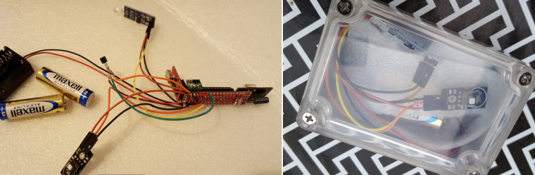
The Dallas temp sensor was never used in this project so please ignore...The node is build with a Slim Node. I could save some power by using a booster with VIn attached to D4. I keep the D4 low between sleeps. In sleep mode it consumes less than 10uA.
The code:
// Enable debug prints to serial monitor
#define MY_DEBUG

// Enable and select radio type attached
#define MY_RADIO_NRF24                  //The radio we use!
#define MY_NODE_ID 19                      //Fixed node ID
#define MY_BAUD_RATE 9600           //Needs to be defined because standard for MySensors is 115200. This bootloader uses 9600!

#include <SPI.h>
#include <MySensors.h>
#include <Vcc.h>

//SketchInfo MySensors
#define SKETCH_NAME "UV #19"                // Change to a fancy name you like
#define SKETCH_VERSION "1.4"                // Your version

//Light
#define CHILD_ID_LIGHT 1
#define LIGHT_SENSOR_ANALOG_PIN A0
#define SENSORS_POWER_PIN 4
MyMessage light_Msg(CHILD_ID_LIGHT, V_LIGHT_LEVEL);

//===================================================
// UVM30A ultraviolet detector.
//
// Thanks to core_c @ mysensors.org for code and info!
// The sensor's VCC is connected to +5V
//
// At first glance, the datasheet is not entirely making sense:
//  "输出电压" translates to "Output voltage", with a value of: DC 0—1V.
//  So the sensor will never output/measure the 2 highest values listed in the graph & table of the datasheet (1079 and 1170+).
//  The datasheet explains it: "(对应 UV 指数 0-10)" translates to "(corresponding to UV index 0-10)".  Fair enough.
//
//  "测试精度" translates to: "Test accuracy", with a value of: ±1 UV INDEX
//  That is not very accurate on a range 0-10. Example: if the real UV-index is 4, you could measure 3, or 5.
//  For that reason we take an average of multiple samples, to get a better measurement.

#define UV_PIN A1
#define CHILD_ID_UV 0
MyMessage uv_Msg(CHILD_ID_UV, V_UV);
const int UV_threshold[12] = {50, 227, 318, 408, 503, 606, 696, 795, 881, 976, 1079, 1170}; // // The list of UV index thresholds in units of mV

// The read value is a 10-bit value, ranging from 0 to 2^10-1 (0 to 1023).
// The reference voltage on the input pin is set to 1.1V.
// That voltage is spread out over the 1024 possible values of a sample.
// So our achieved resolution equals (1.1 Volts / 1024) = 0.00107421875 Volt.
// The UVM30A sensor datasheet lists all UV-index values according to measured milli-Volts.
const float SAMPLE_TO_MV = (1.1 * 1000) / 1024; // mV per sample-resolution

uint16_t UV_value;
uint16_t UV_index;        // the UV index
uint16_t UV_index_f;      // the fractional part of the UV index

// Compiler directives for averiging the UV-sensor readings
// (Change the values of UV_AVERAGE_T & UV_AVERAGE_N according to your own taste).
#define UV_AVERAGE_T 4000 // Sample interval duration in milliseconds..  (1 <= T <= 60000)
#define UV_AVERAGE_N 10   // ..During that interval, N samples are taken, and averaged.    (1 <= N <= 100, must be <>0)

#if UV_AVERAGE_T < 1      // Sanity check. It must be dummy proof
#define UV_AVERAGE_T 1
#endif
#if UV_AVERAGE_N < 1      // Sanity check. It must be dummy proof
#define UV_AVERAGE_N 1    // This value must be <>0 at all times, because we divide by it
#endif

// calculate once, use many times in the loop()
const float UV_AVERAGE_N_RP = 1.0 / UV_AVERAGE_N;
const uint32_t UV_AVERAGE_D = UV_AVERAGE_T * UV_AVERAGE_N_RP;
//===================================================

//SleepTime
unsigned long SLEEP_TIME = 600000; // Sleep time between reads (in milliseconds)

//Battery
const float VccMin   = 1.9;           // Minimum expected Vcc level, in Volts.
const float VccMax   = 3.0;           // Maximum expected Vcc level, in Volts.
const float VccCorrection = 1.0 / 1.0; // Measured Vcc by multimeter divided by reported Vcc

Vcc vcc(VccCorrection);

void presentation()  {
  // Send the sketch version information to the gateway and Controller
  sendSketchInfo(SKETCH_NAME, SKETCH_VERSION);

  // Register all sensors to gateway (they will be created as child devices)
  present(CHILD_ID_UV, S_UV);
  present(CHILD_ID_LIGHT, S_LIGHT_LEVEL);

}

void setup()  {

  analogReference(INTERNAL);

  pinMode(SENSORS_POWER_PIN, OUTPUT);
  pinMode(UV_PIN, INPUT);
  pinMode(LIGHT_SENSOR_ANALOG_PIN, INPUT);

}

void loop()
{

  digitalWrite(SENSORS_POWER_PIN, HIGH);  //Set power on digital pin for lightsensor.
  wait(500); //Wait 500ms to make sure lightsensor is powered and stable.

  processUV();   //Read UV

  readLightLevel();   //Read Light

  digitalWrite(SENSORS_POWER_PIN, LOW); // Set power for lightsensor off to save power.

  BatteryCalculation();

  //Sleep!
  sleep(SLEEP_TIME);
}

void readLightLevel()      {
  int lightLevel = (1023 - analogRead(LIGHT_SENSOR_ANALOG_PIN)) / 10.23; //To get a value ranging from 0 (dark) to 100 (bright).

#ifdef MY_DEBUG
  Serial.print("Light: "); Serial.println(lightLevel);
#endif
  send(light_Msg.set(lightLevel));

}

//===================================================
// Process a UV measurement:
// read an average value from the UV detector.
// The average consists of N samples taken during a T milliseconds interval.
//===================================================
void processUV() {
  // Set the reference voltage for sampling
  // For our ATmega328 Nano: INTERNAL = 1.1V, DEFAULT = 5V
  // After using analogReference(), the first few samples may not be accurate (according to the Arduino language reference),
  // and that is why we read a few dummy samples before starting the actual measurement.
  // NOTE: If you change the next statement, beware to adjust the value of SAMPLE_TO_MV too.

  for (int i = 0; i < 10; i++) UV_value = analogRead(UV_PIN); // ignore the possibly inaccurate samplevalues.

#ifdef MY_DEBUG
  Serial.print("UV raw values: [");
#endif
  uint32_t average = 0;
  for (int i = 0; i < UV_AVERAGE_N; i++) {
#ifdef MY_DEBUG
    UV_value = analogRead(UV_PIN);
    Serial.print(UV_value);  Serial.print(" ");
    average += UV_value;
#else
    average += analogRead(UV_PIN);
#endif
    delay(UV_AVERAGE_D);
  }
  UV_value = average * UV_AVERAGE_N_RP;
#ifdef MY_DEBUG
  Serial.print("]    avg: ");  Serial.print(UV_value);
#endif

  // We must convert sample-values into mV-values before we look up the UV-index.
  UV_value *= SAMPLE_TO_MV;

#ifdef MY_DEBUG
  Serial.print("     mV: ");  Serial.print(UV_value);
#endif

  // determine the UV index
  if (UV_value < UV_threshold[0]) {
    // too low value  or  invalid value (in case the sensor is wrongly connected it always returns 0)
    UV_index = 0;
    UV_index_f = 0;
  } else {
    for (UV_index = 11; UV_index > 0; UV_index--) {
      if (UV_value >= UV_threshold[UV_index]) break;
    }
    // calculate fractional part of the UV-index
    if (UV_index == 11) {
      // already at the maximum level; Displaying a fraction is meaningless
      UV_index_f = 0;
    } else {
      UV_index_f = map(UV_value, UV_threshold[UV_index], UV_threshold[UV_index + 1], 0, 9); // one decimal, so a number ranging 0 to 9
    }
  }
  float UV_index_float = UV_index + (UV_index_f * 0.1); // that is the same as /10

#ifdef MY_DEBUG
  Serial.print("     UV index: ");  Serial.println(UV_index_float);
#endif

  send(uv_Msg.set(UV_index_float, 1));

}


void BatteryCalculation()
{
  float v = vcc.Read_Volts();

#ifdef MY_DEBUG
  Serial.print("VCC = ");
  Serial.print(v);
  Serial.println(" Volts");
#endif
  float p = vcc.Read_Perc(VccMin, VccMax);

#ifdef MY_DEBUG
  Serial.print("VCC = ");
  Serial.print(p);
  Serial.println(" %");
#endif

  sendBatteryLevel(p);

}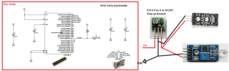
And offcourse the sensors analog output was connected to analog input of the atmega - forgot that in the schematics. UV=A0 and Light =A1