Air Quality Sensor
-
@tantt2810 sorry for not being more responsive, I left MQ/TGS behind me but I've not kept all my notes on mesuring this and that, that would require me to search for it again. But I appreciate if you can spot me some float/type error conversion in sketches !
-
I was a bit disappointed when a project I contributed to on Kickstarter showed the inside of their boxes, I wonder how they will manage to satisfy customers with calibration... or their home made index as netatmo did
-
Used the air quality script for MQ7 but throwed out all the conversions and calibrations. Just reading the plain input from the analogue pin.
I targeted this as a smoke detector but it seems this sensor highly depends on the humidity of the surrounding air. Are there any existing formulas to correct for the humidity of the surounding air?And on one sensor i have some irratical data as shown below (blue). I wonder if it's a power supply (black and green is DHT) or a broken sensor?
@moskovskiy82 well looks like a strange sensor... try averaging several samples/// always remember to have it running several days before measuring for there are chemical left from china factories...
-
Hey all,
I've got a question regarding the calibration function in https://github.com/empierre/arduino/blob/master/AirQuality-Multiple_Gas_Sensor1_4.ino :
$ grep MQCalibr *
AirQuality-Multiple_Gas_Sensor1_4.ino:  Ro0 = MQCalibration(MQ2_SENSOR,10,RL0,SmokeCurve);
AirQuality-Multiple_Gas_Sensor1_4.ino:  Ro1 = MQCalibration(MQ6_SENSOR,10,RL1,LPGCurve);
AirQuality-Multiple_Gas_Sensor1_4.ino:  Ro2 = MQCalibration(MQ131_SENSOR,10,RL2,O3Curve);
AirQuality-Multiple_Gas_Sensor1_4.ino:  Ro3 = MQCalibration(TGS2600_SENSOR,10,RL3,C2H5OH_terCurve);
AirQuality-Multiple_Gas_Sensor1_4.ino:  Ro4 = MQCalibration(MQ135_SENSOR,10,RL4,CO_secCurve);
AirQuality-Multiple_Gas_Sensor1_4.ino:  Ro6 = MQCalibration(TGS2602_SENSOR,1,RL6,C7H8Curve);
....
AirQuality-Multiple_Gas_Sensor1_4.ino:float MQCalibration(int mq_pin, double ppm, double rl_value,float *pcurve )
Th function MQCalibration should calibrate the sensor in clean air, the calibration function uses the PPM concentration of the gas in a clean air environment.
You already use the appropriate value for i.e. CO2 (around 399 PPM) in the MQ135 sketch - but why are you using those obscure values in the calibration (1, 10) here?Thanks in advance!
@wreiner said:
Th function MQCalibration should calibrate the sensor in clean air, the calibration function uses the PPM concentration of the gas in a clean air environment.
You already use the appropriate value for i.e. CO2 (around 399 PPM) in the MQ135 sketch - but why are you using those obscure values in the calibration (1, 10) here?Well, I didn't know the concentration in clean air so I had to put in a value even random... I took the hypothesis there are very few in the air so low value.
-
@tantt2810 said:
Hi everyone,
I have an CO2 MG811 sensor. I don't know where tcm pin connect with ?
Please help me. Thank you so much !!!!this is an analogic sensor, so VCC/Gnd to power it, and readings on analogic Aout
@epierre
Thank you. Your mean is Vcc->5V, GND->GND, Dout->Digital pin, Aout->Analog pin. Is it right?
But I don't know the tcm pin connect with ? I have read datasheet but I don't find any info about tcm pin. Please help me. Thank you so much !!! -
I am confused with MiCS 4514 sensor. What I had done is :
using MiCS quick start evaluation board, measured ADC value
calculated Vout and from that calculated R0.
Rs/R0 concentration gives me high value, which is not possible, My data is as follows
clean air file is used for the purpose of R0 value
https://drive.google.com/file/d/0B8sF8a6FHoseWjhWOHRoYzIxakk/view?usp=sharing
and Polluted file is used to calculate the actual pollution
https://drive.google.com/file/d/0B8sF8a6FHoseR1BnclhCUHdibEU/view?usp=sharingI am confused. Please help me
-
@epierre
Thank you. Your mean is Vcc->5V, GND->GND, Dout->Digital pin, Aout->Analog pin. Is it right?
But I don't know the tcm pin connect with ? I have read datasheet but I don't find any info about tcm pin. Please help me. Thank you so much !!!@tantt2810 said:
@epierre
Thank you. Your mean is Vcc->5V, GND->GND, Dout->Digital pin, Aout->Analog pin. Is it right?
But I don't know the tcm pin connect with ? I have read datasheet but I don't find any info about tcm pin. Please help me. Thank you so much !!!do not use the digital pin !!! it only reacts with the potentiometer in on/off mode, so useless... you need to power the device with Vcc/Gnd, and read the output with Aout (A stands for analog). The last one forget it.
-
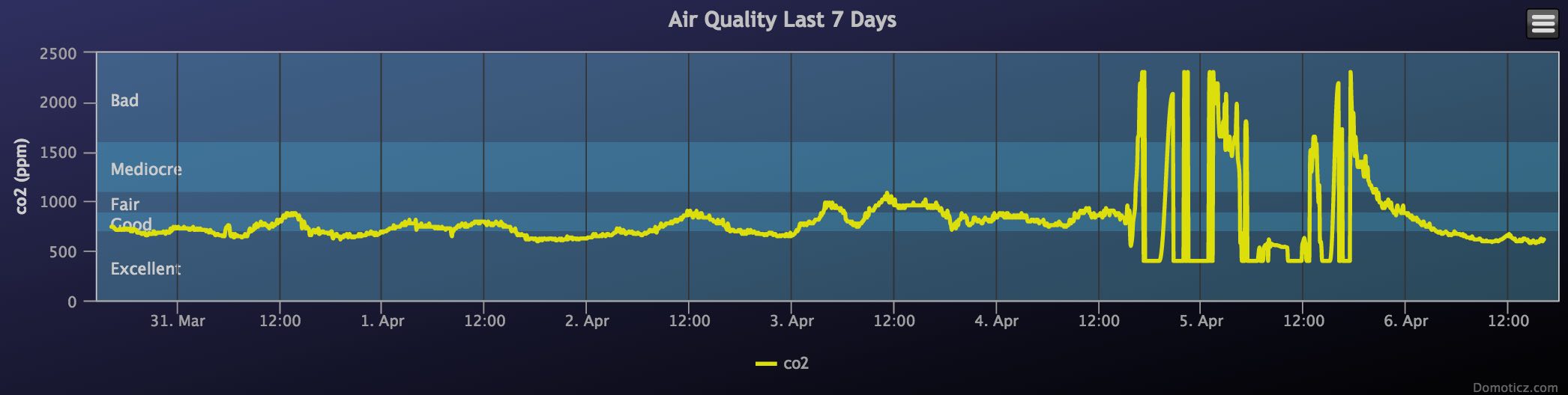
Readings of my MQ135 are going up and down like a yo-yo. Not sure how to read them really?
What do you think?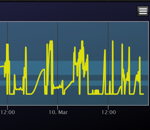
@alexsh1 is that raw ADC output or with a calculation ? normaly this should go up or down but not in sucha drastic way
z-wave - Vera -> Domoticz
rfx - Domoticz <- MyDomoAtHome <- Imperihome
mysensors -> mysensors-gw -> Domoticz -
@alexsh1 is that raw ADC output or with a calculation ? normaly this should go up or down but not in sucha drastic way
-
@tantt2810 said:
@epierre
Thank you. Your mean is Vcc->5V, GND->GND, Dout->Digital pin, Aout->Analog pin. Is it right?
But I don't know the tcm pin connect with ? I have read datasheet but I don't find any info about tcm pin. Please help me. Thank you so much !!!do not use the digital pin !!! it only reacts with the potentiometer in on/off mode, so useless... you need to power the device with Vcc/Gnd, and read the output with Aout (A stands for analog). The last one forget it.
-
This is a value gw.send(msg.set(MQ135_DEFAULTPPM+(int)ceil(valAIQ))) reported to Domoticz.
It does not make any sense to me at all. -
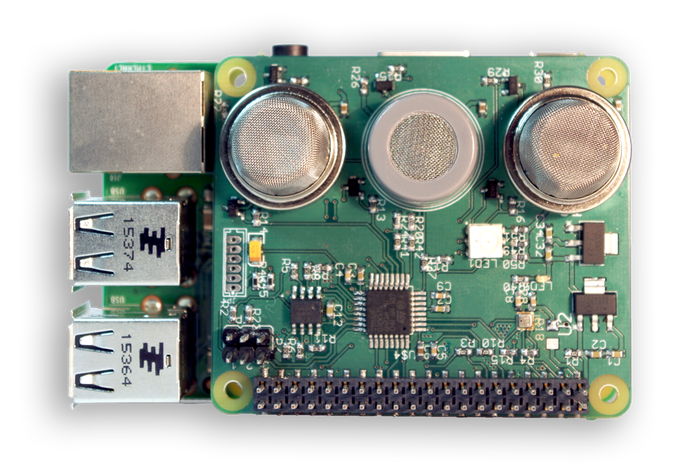
For those who are trying to use an MQ135 module from e-bay or other sellers, on a small pcb with a chip, LED and potmeter:
It took me a while until I figured out that the little chip has a very big influence on the value that you read on the A-out pin.
Only after removing the connection between the A-out pin and the little chip, I got normal measurements.I also replaced the small resistor marked "102" with a 10k resistor, to make measurements more compatible with code that uses a 10k pull down resistor. But that was already a known issue, found on many other places.
-
Hello,
Can I use pinMode(digitalpin, OUTPUT) to turn off sensor? Or Is there any way to wirte a function that turn off sensor?
I want to remote it on web to turn on or off it.
Thank you so much !!!
@tantt2810 said:
Hello,
Can I use pinMode(digitalpin, OUTPUT) to turn off sensor? Or Is there any way to wirte a function that turn off sensor?
I want to remote it on web to turn on or off it.
Thank you so much !!!
well no, powering is through Vcc/GND, so you whould use a switch on this. Digital pins do not gives enough power for such sensors.
-