Air Quality Sensor
-
Davide answered me, lot of things to read but a warning:
Anyway, for consistent CO2 investigaion, you HAVE to chose a NDIR sensor, those chemical sensor can not be used. They decay in a few year, and they differs a little one from each other.I've asked him back for precision if he speaks of the organic sensor or the ceramic ones (like MQ...).
For the CO2, it is MH-Z14 which is $66+ priced.
-
-
@korttoma look above to S_CO2Sensor.json D_CO2Sensor.xml D_CO2Sensor.json, if you can test it...
@epierre said:
@korttoma look above to S_CO2Sensor.json D_CO2Sensor.xml D_CO2Sensor.json, if you can test it...
Thanks, found the device files and got the device included again.
Seems like my MQ-2 is always reporting 0 or nothing at all. I guess I need to try to calibrate it again.
It will do the calibration every time the sensor is restarted right?
How can I calibrate the sensor if I put it somewhere where the air is not clean enough? (bring clean air in a jar? ;) )Maybe it would be an idea to add a calibration button to the mix and when run using the button it would save the calibration related data in the RAM so it can then always use this calibrated value and then it would not re-calibrate every time it loses power.
I have the 10k resistor between GND and A0, is this really necessary?
Does the potentiometer on the sensor board affect the analog out at all or is it only for sensitivity on the digital out?Sorry for all the questions ;)
- Tomas
-
@epierre said:
@korttoma look above to S_CO2Sensor.json D_CO2Sensor.xml D_CO2Sensor.json, if you can test it...
Thanks, found the device files and got the device included again.
Seems like my MQ-2 is always reporting 0 or nothing at all. I guess I need to try to calibrate it again.
It will do the calibration every time the sensor is restarted right?
How can I calibrate the sensor if I put it somewhere where the air is not clean enough? (bring clean air in a jar? ;) )Maybe it would be an idea to add a calibration button to the mix and when run using the button it would save the calibration related data in the RAM so it can then always use this calibrated value and then it would not re-calibrate every time it loses power.
I have the 10k resistor between GND and A0, is this really necessary?
Does the potentiometer on the sensor board affect the analog out at all or is it only for sensitivity on the digital out?Sorry for all the questions ;)
@korttoma said:
Thanks, found the device files and got the device included again.
So you confirm they can be used as is ?
@korttoma said:
Seems like my MQ-2 is always reporting 0 or nothing at all. I guess I need to try to calibrate it again.
It will do the calibration every time the sensor is restarted right?
How can I calibrate the sensor if I put it somewhere where the air is not clean enough? (bring clean air in a jar? wink )this is the ongoing work, except CO2 which is known to be 399ppm (co2now.org) that should report this in clean air, for the other that should be little, and for deadly gases a full warning if this is high.
@korttoma said:
Maybe it would be an idea to add a calibration button to the mix and when run using the button it would save the calibration related data in the RAM so it can then always use this calibrated value and then it would not re-calibrate every time it loses power.
That is an option, but EEPROM has a 100k write cycle only... this is what citizensensors says about it:
1) Metal oxide gas sensors have intrinsic drift over time i.e. it is necessary to perform calibration on a regular basis.

2) Because of spread in baseline resistance, sensitivity, cross-sensitivity, temperature dependency it is not possible to apply same calibration parameters to all the sensors.

3) This type of sensor is efficient to detect change in concentration but not well adapted to absolute readings because of multiple dependency (T, RH, cross-contaminants).

4) Using smart algorithm allows indicating useful information like the correlation with CO2 in confined space like offices or buildings (see VZ-87 in attachment).

For absolute readings with high accuracy and repeatability I agree with you that you should use another technology.
From this we have the calibration issue... in another post, since they only report resistance, they say they will rebuild all their platform to address callibration issue... but since calibration depends only from a reference gas concentration... only the pre-calibrated sensors remains viable for the low cost MQ/MICS/TGS will never be really calibrated...
@korttoma said:
I have the 10k resistor between GND and A0, is this really necessary?
Does the potentiometer on the sensor board affect the analog out at all or is it only for sensitivity on the digital out?no you can remove it, I have observed a different behavior when moving it, it looks like it is shared by both digital and analogic for the same reason. What I'd like to find is where to measure the resistance for there are often some more on the board.
@korttoma said:
Sorry for all the questions
good questions are always useful, especially when they meet my current subject of interrest ;-)
z-wave - Vera -> Domoticz
rfx - Domoticz <- MyDomoAtHome <- Imperihome
mysensors -> mysensors-gw -> Domoticz -
@korttoma said:
Thanks, found the device files and got the device included again.
So you confirm they can be used as is ?
@korttoma said:
Seems like my MQ-2 is always reporting 0 or nothing at all. I guess I need to try to calibrate it again.
It will do the calibration every time the sensor is restarted right?
How can I calibrate the sensor if I put it somewhere where the air is not clean enough? (bring clean air in a jar? wink )this is the ongoing work, except CO2 which is known to be 399ppm (co2now.org) that should report this in clean air, for the other that should be little, and for deadly gases a full warning if this is high.
@korttoma said:
Maybe it would be an idea to add a calibration button to the mix and when run using the button it would save the calibration related data in the RAM so it can then always use this calibrated value and then it would not re-calibrate every time it loses power.
That is an option, but EEPROM has a 100k write cycle only... this is what citizensensors says about it:
1) Metal oxide gas sensors have intrinsic drift over time i.e. it is necessary to perform calibration on a regular basis.

2) Because of spread in baseline resistance, sensitivity, cross-sensitivity, temperature dependency it is not possible to apply same calibration parameters to all the sensors.

3) This type of sensor is efficient to detect change in concentration but not well adapted to absolute readings because of multiple dependency (T, RH, cross-contaminants).

4) Using smart algorithm allows indicating useful information like the correlation with CO2 in confined space like offices or buildings (see VZ-87 in attachment).

For absolute readings with high accuracy and repeatability I agree with you that you should use another technology.
From this we have the calibration issue... in another post, since they only report resistance, they say they will rebuild all their platform to address callibration issue... but since calibration depends only from a reference gas concentration... only the pre-calibrated sensors remains viable for the low cost MQ/MICS/TGS will never be really calibrated...
@korttoma said:
I have the 10k resistor between GND and A0, is this really necessary?
Does the potentiometer on the sensor board affect the analog out at all or is it only for sensitivity on the digital out?no you can remove it, I have observed a different behavior when moving it, it looks like it is shared by both digital and analogic for the same reason. What I'd like to find is where to measure the resistance for there are often some more on the board.
@korttoma said:
Sorry for all the questions
good questions are always useful, especially when they meet my current subject of interrest ;-)
@epierre said:
@korttoma said:
Thanks, found the device files and got the device included again.
So you confirm they can be used as is ?well, for the device in Vera I had to change the parameter "device_file" from "D_AirQuality1.xml" to "D_CO2Sensor.xml".
I don't get any errors but I also do not get any values but I guess this is because my node is not sending any values.I'll try to look in to why my node is not reporting any value and try to remove the 10kR and see if I can measure the load resistance of my MQ-2 sensor board and maybe even remove some unnecessary components from it...
-
Hi All. Very interesting stuff, thanks all for sharing! I'm attempting to integrate an MQ-2, MQ-6 and MQ-135 (sensors only, no boards) using parts of epierre's sketch but I'm confused on a few things on how to set it up properly:
- What resistor(s) should go between A0 and ground? Keep in mind I'm not using a sensor board with built in protection resistor. Should there be a protection resistor then an adjustable pot for calibration?
- define RL_VALUE (5)
-- does this refer to the size of the protection resistor between A0 and ground? - define RO_CLEAN_AIR_FACTOR (9.83)
-- does this value need to change at all? - float Ro4 = 2.511;
-- when you say this needs to be tuned to 10k, does that mean put a pot between A0 and ground and adjust until the calibration R0 is 10k?
Sorry for all the questions, I appreciate any input! Thanks!
1- see http://www.electronicaestudio.com/docs/SHT-114.pdf Fig 2 for wiring, the adjustable resistance is with ground and the sensor.
2- yes
3- Ro is calculated on first launch expecting you do this outside.
Ro = MQCalibration(MQ_SENSOR_ANALOG_PIN);4- this is a default value I observed here. again the datasheet recommands for MQ135 20K to be in range with their values:
we recommend that you calibrate the detector for 100ppm NH3 or 50ppm Alcohol concentration in air and use value of Load resistance that( RL) about 20 KΩ -
1- see http://www.electronicaestudio.com/docs/SHT-114.pdf Fig 2 for wiring, the adjustable resistance is with ground and the sensor.
2- yes
3- Ro is calculated on first launch expecting you do this outside.
Ro = MQCalibration(MQ_SENSOR_ANALOG_PIN);4- this is a default value I observed here. again the datasheet recommands for MQ135 20K to be in range with their values:
we recommend that you calibrate the detector for 100ppm NH3 or 50ppm Alcohol concentration in air and use value of Load resistance that( RL) about 20 KΩThanks for fast reply! I think i understand all but point #4... What do you mean by the Ro needs to be tuned to 10k? Using the adjustable resistor? Does that mean that the calibration number in fresh air at startup should ideally reach a set number, 10k?
Since I don't have access to properly calibrate the sensor against a know quantity of gas, I thought the rough calibration would occur in clean air at start up, is that correct?
Sorry for all the questions, it's a bit complicated. Thanks again!
-
Thanks for fast reply! I think i understand all but point #4... What do you mean by the Ro needs to be tuned to 10k? Using the adjustable resistor? Does that mean that the calibration number in fresh air at startup should ideally reach a set number, 10k?
Since I don't have access to properly calibrate the sensor against a know quantity of gas, I thought the rough calibration would occur in clean air at start up, is that correct?
Sorry for all the questions, it's a bit complicated. Thanks again!
@pbo as stated above, the sensors evolve in their life... let's say that the value recommended by the datasheet is the best if you can.
clean air calibration means that you should have a 0 value in clean air. Let's say that for CO2 the actual value is 399... so it should not be 0, but the clean air calibration is "assumed" quite good for LPG, SO2, NOx... that should be present in very little quantity, and again this is when the value increases a lot that it gets dangerous... there are some discussion on this above.
-
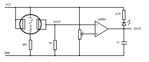
I tried to analyze what is on the small ciscuitboar for my MQ-2 sensor an here is what I think it contains:
So adding the 10K between AOUT and GND is pointless. So what now? Can I use it as is and just use the 1K value for RL in the sketch or is it recommended to change the 1K to something else (10K)??
-
@epierre Couldn't find it either, sorry...
I wouldn't buy a $52,- component without a datasheet, if I were you...@Yveaux right, I opened a dispute with the seller, since I observed also no/nearly no answer to match burning with the sensor, he didn't even answer thus closing the dispute in my favor... that will be a good warning to me about those undocumented sensors comming from only one supplier without datasheet... there are other around, I shall avoid them..
-
I tried to analyze what is on the small ciscuitboar for my MQ-2 sensor an here is what I think it contains:
So adding the 10K between AOUT and GND is pointless. So what now? Can I use it as is and just use the 1K value for RL in the sketch or is it recommended to change the 1K to something else (10K)??
@korttoma You've been lucky finding such a schema, but it is strange there is a resistance on the other side of the sensor, and the variable one is not where expected... maybe the 1K is wrong on the schema, can you mesure it on the board?
5.1 Ohm is low...
The RL here is for the voltage comparator that gives the digital output with led.
MQ-2 datasheet asks for Rs in 3KΩ-30KΩ
If this is right, then the value that the autocalibration "in clean air" should give you something around 1K.The MQ-9 datasheet is a bit more versatile:
Power of Sensitivity body(Ps): Ps=Vc^2×Rs/(Rs+RL)^2
Resistance of sensor(Rs): Rs=(Vc/VRL-1)×RLMQ-9: Rs(in air)/Rs(100ppm CO)≥5
I fear they are using a standard board for all sensors and that the resistance value may be wrong from this, just because they want to deliver a digital signal...
z-wave - Vera -> Domoticz
rfx - Domoticz <- MyDomoAtHome <- Imperihome
mysensors -> mysensors-gw -> Domoticz -
@korttoma You've been lucky finding such a schema, but it is strange there is a resistance on the other side of the sensor, and the variable one is not where expected... maybe the 1K is wrong on the schema, can you mesure it on the board?
5.1 Ohm is low...
The RL here is for the voltage comparator that gives the digital output with led.
MQ-2 datasheet asks for Rs in 3KΩ-30KΩ
If this is right, then the value that the autocalibration "in clean air" should give you something around 1K.The MQ-9 datasheet is a bit more versatile:
Power of Sensitivity body(Ps): Ps=Vc^2×Rs/(Rs+RL)^2
Resistance of sensor(Rs): Rs=(Vc/VRL-1)×RLMQ-9: Rs(in air)/Rs(100ppm CO)≥5
I fear they are using a standard board for all sensors and that the resistance value may be wrong from this, just because they want to deliver a digital signal...
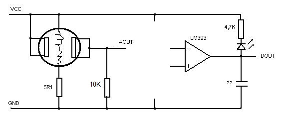
I did not find the schema, I measured the board and figured it out myself so it might be wrong.
Could you draw a schema that would show me exactly how it would preferably look so I can change it? Because I'm clearly not smart enough to understand it from your descriptions. Please explain it to me like I was 4 years old ;)
-
Now changed my sensor according to this (disconnected the OP related to DOUT) :
Please confirm that this is how it is preferred to be connected.
- Tomas
-
Now changed my sensor according to this (disconnected the OP related to DOUT) :
Please confirm that this is how it is preferred to be connected.
Hello,
I guess here you have the same that the datasheet, so I assume it is ok ;-)
I've been working to port sketches to a Spark Core with good results, the 12 bits ADC gives more precise values, at least the MQ135 is now very sensitive.
I am also correcting errors in the sketches I have produced.
-
Hello,
A good article on the comparison of 3 same MQ-7 sensors
A lot of good questions, not easy to answer! It is good you tryed it with three sensors instead of just one, and you can see there is a lot of variation from one sensor to the next of the same batch. [...] As to the value of Ro, that is the million dollar question. You have to have a known calibration source of CO in order to determine that! Each MQ-7 sensor will be different. The normal levels in a lab or home will be (should be!) well below the level that this sensor can detect and discriminate. It's lower limit implied in the data sheet is around 50ppm, which is where it begins to be dangerous for continuous exposure. Do read wiki and other sources about carbon monoxide and levels that can occur under different conditions. -
During the weekend I did the hardware changes and tried my MQ-2 sensor again and now if I hit it with smoke (I have smoke on a can) I do get values in Vera under the Variable1 property. No values on the dashboard device itself. I guess some changes are needed for the device file to display the V_VAR1 or we should use something else than V_VAR1.
If you have already updated the sketch for the MQ-2 please let me know where I can get the latest version so I can try it out.
btw, is the MQ-2 supposed to give the value 0 after it is calibrated in clean air? My sensor sends the value 0 all the time unless I hit it with my smoke can.
-
@korttoma said:
If you have already updated the sketch for the MQ-2 please let me know where I can get the latest version so I can try it out.
btw, is the MQ-2 supposed to give the value 0 after it is calibrated in clean air? My sensor sends the value 0 all the time unless I hit it with my smoke can.
Yes I am deeply modifying it, and will have a question for @hek : to have something consistant in time, it owuld be better to have the initial calibration stored, either in EEPROM or as a VAR on the server. Could it be possible that I introduce a loop that wait till the var is answered and if not go into calibration ?
@korttoma the best sketch so far is the following, to be scaled down to one sensor, remove specific Mega initialization. I will make a simpler one based on this soon, as I have already done it for the Spark core.
https://github.com/empierre/arduino/blob/master/MQv01dgi_1_4.inoz-wave - Vera -> Domoticz
rfx - Domoticz <- MyDomoAtHome <- Imperihome
mysensors -> mysensors-gw -> Domoticz -
@korttoma said:
If you have already updated the sketch for the MQ-2 please let me know where I can get the latest version so I can try it out.
btw, is the MQ-2 supposed to give the value 0 after it is calibrated in clean air? My sensor sends the value 0 all the time unless I hit it with my smoke can.
Yes I am deeply modifying it, and will have a question for @hek : to have something consistant in time, it owuld be better to have the initial calibration stored, either in EEPROM or as a VAR on the server. Could it be possible that I introduce a loop that wait till the var is answered and if not go into calibration ?
@korttoma the best sketch so far is the following, to be scaled down to one sensor, remove specific Mega initialization. I will make a simpler one based on this soon, as I have already done it for the Spark core.
https://github.com/empierre/arduino/blob/master/MQv01dgi_1_4.ino -
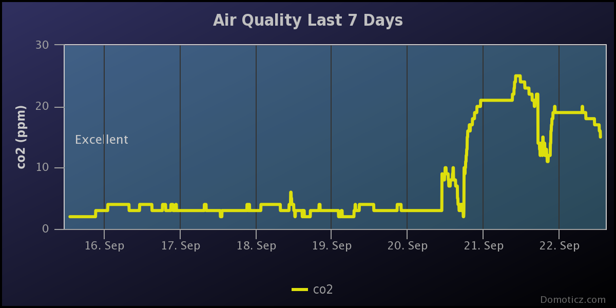
Now some questions I have currently:
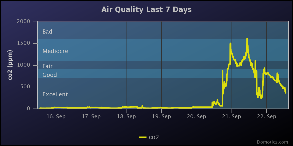
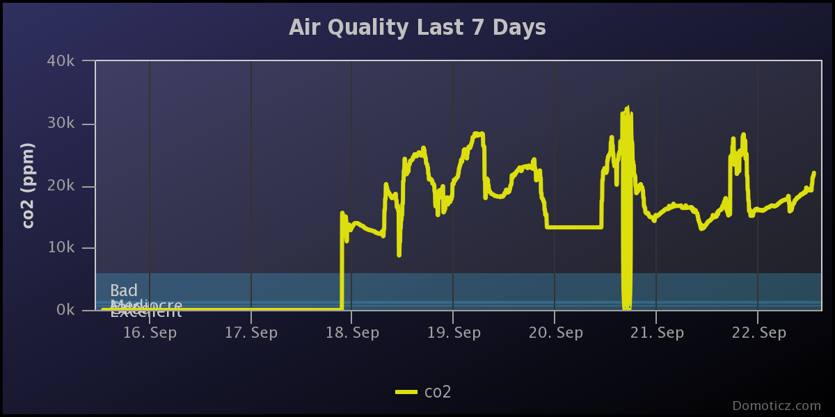
I've used your clean air calibration in open air given values of air concentration where appropriate. Around sept 20th I applied this method t omy sketches and I have since sensors that are very much more reactive ! Only 2SH12 has no curve, it is voltage for this (damn) sensor doesn't have a datasheet...
I don't know if this was this predictible...
They are all placed inside a room that I sometime open to clean air. Also there are restarts that calculates again those values where you see it drop maybe, but anyway it will still go to the previous values.
MQ135 in CO2:
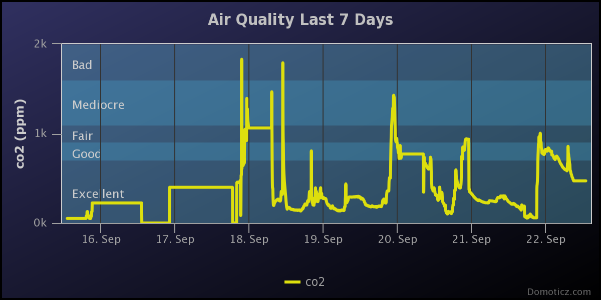
MQ2 in Smoke:
2SH12 in SO2 in voltage:
MQ6 in O3: