110v-230v AC to Mysensors PCB board
-
I spoke too soon... the unit seems to work well, but I hadn't tested if the relay actually switched or not. The status seems to change fine in the serial monitor, but it doesn't seem to be actually switching. I'll have to do some more troubleshooting.
-
@mvdarend Thanks for the feedback! Happy to hear that it's working fine on your side as well. Although I do find it strange that the LE33 seems to be the other way around on your board? Maybe I just made a mistake with the silkscreen, and should the LE33 be on the bottom side? Anyway, I'll make sure to address this as soon as I possible (probably somewhere during next week). Sorry for the possible inconvenience, but thanks for pointing this out! :)
@sundberg84 The board dimension are about 4.2x4.7cm, so it is quite small. However, I'm afraid that because of the NRF24L01 module, and the 230v connections to it, it wouldn't really fit the box you have on that picture (assuming the board you have there is 5x5cm)..
Somewhere in the next week or 2 I'll try to design a custom 3d printable plastic box for the board that I've designed. Together with a 2-relay board as requested by @jemish .
@aproxx My first project with your design, Thanks :+1:
p.s. the regulator needs to be mounted "reversed" from the silk screen. Some puzzling but a lot of fun and top result :heartbeat:
-
Is it possible to add the option to be able to use RFM69 radio also?
-
The board looks really nice! Just one question though; what about temperature protection? In this thread people talks about gluing a thermal fuse on top of the HLK-PM01, is that something you considered or do you think it's unnecessary?
-
The board looks really nice! Just one question though; what about temperature protection? In this thread people talks about gluing a thermal fuse on top of the HLK-PM01, is that something you considered or do you think it's unnecessary?
@cygnus said:
The board looks really nice! Just one question though; what about temperature protection? In this thread people talks about gluing a thermal fuse on top of the HLK-PM01, is that something you considered or do you think it's unnecessary?
Good point, been following this topic because of the other topic about the HLK-PM01 ad to dc regulator. And after extensive testing the outcome was that there should be added the thermal fuse because of additional safety. What do you all think?
-
@cygnus said:
The board looks really nice! Just one question though; what about temperature protection? In this thread people talks about gluing a thermal fuse on top of the HLK-PM01, is that something you considered or do you think it's unnecessary?
Good point, been following this topic because of the other topic about the HLK-PM01 ad to dc regulator. And after extensive testing the outcome was that there should be added the thermal fuse because of additional safety. What do you all think?
@krizzziz
I have seen in some commercial wall switches thermal cutoff/fuses they are usually to the top of the offending (heat producing components) not necessarily directly touching. I have definitely added them to mine for peace of mind. Like this one:
http://i.imgur.com/rqOawGmm.jpgJust make sure you heat sink when soldering them into place and check them after installation.
-
NIce little boards! I received mine yesterday :) after a few hiccups I got it working fairly quickyl.
Two small things that might need your attention:
- The holes for fuse2 were too small for the resettable fuses I bought, had to drill them out a tiny bit.
- I think the LE33 is the wrong way around in the pictures. I kept getting a "Check wires" message in the debugger. After checking a number of things I noticed that the voltage to the radio was too high. After looking at the diagrams I noticed that the LE33 is the wrong way around, after desoldering and turning it around (flat side facing Fuse2) the unit worked as expected.
For anyone else that bought the 5.5v DC varistors from the given link, double check them before using them. I received a few that were defective, there was absolutely no resistance between the two poles. Causing Fuse2 to get a bit warm :)
-
I'm trying to build this nice litte board. Got a long way but now i'm stuck.
The BOM for version 3.2.3
100nF + 100pF Capacitors
4.7uF CapacitorsSchematics.
c1 100nF
c2 100uF
c3 4.7ufI'm don't have a lot of knowlegde but the 100uF seems te be missing from the BOM. The placement of this part is under the HLK. I have a lot of trouble place the C1 and C2.
I have a ceramic one with number 104 in C2. I thought this is the 100nF. So should it be in C1? But it's so small and nice. And then C2 is missing from the BOM and the only 100uF I have from an other project is big. It realy won't fit under the HLK.
Can some-one give some insight on the BOM, C1 and C2, Ceramic code numbers.
This would realy help me and maybe a few others.Also on my board the holes for the fuse 2 where to small had to drill them out. Second the request for a thermal-fuse. But thanks for this great design.
-
@aproxx Could you clarify the capacitors please? C2 on a post in this thread is 100uF but there are hard to get as ceramics and even the half height ones I have make the arduino stand very high off the board.
Thanks muchly!
@shabba http://nl.aliexpress.com/item/100pcs-lot-Multilayer-ceramic-capacitor-0-1uF-104-50V-100nF-104M/32429917283.html?ws_ab_test=searchweb201556_7_79_78_77_80,searchweb201644_5,searchweb201560_7
you can solder these under the processor board
the 100uF does not have to be a ceramic one...
-
thanks for reply @AWI - The 100nf one does not go under - it is the 100uF one that does. I have a small electrolytic one (it is slightly smaller than the second link you mention) and there is still not enough space - my arduino is too low - I could try and find higher pin stands. I'm sure some ppl will go off and buy all these parts like me so I hope they are aware. Would have been ideal for a SMD really (like the varistor right beside it).
-
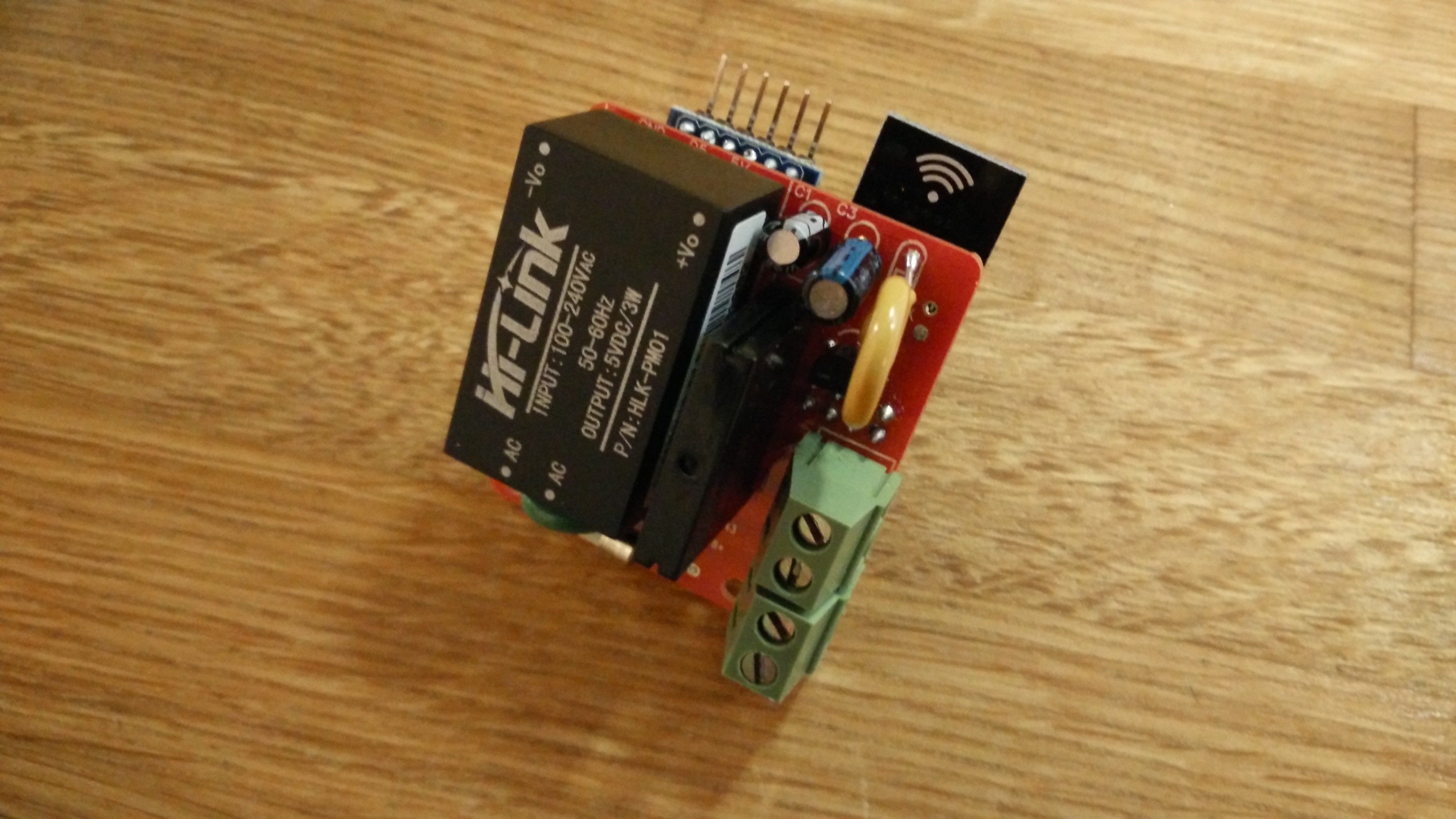
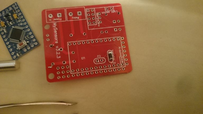
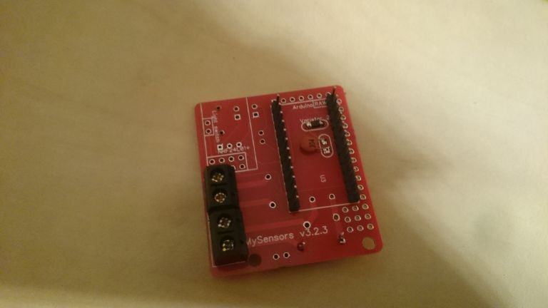
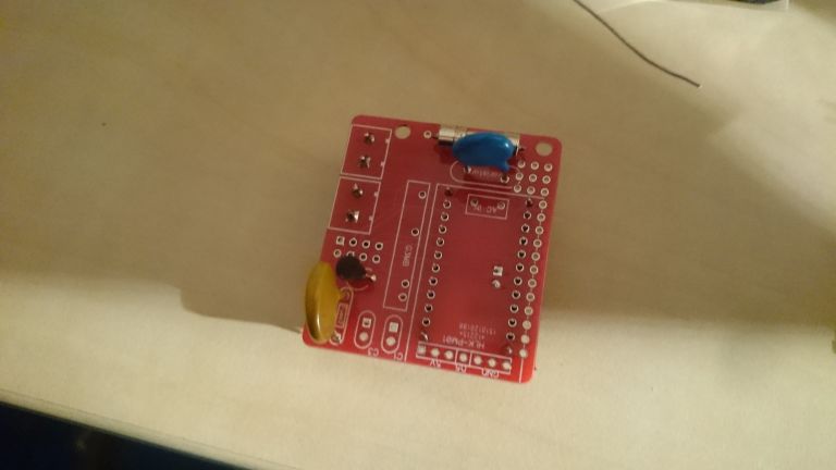
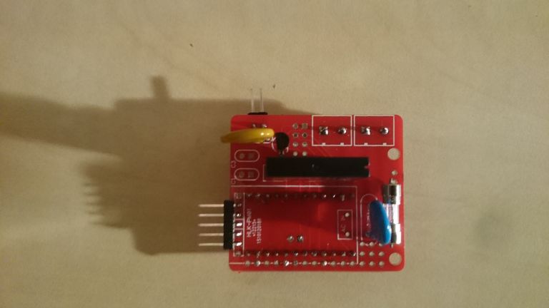
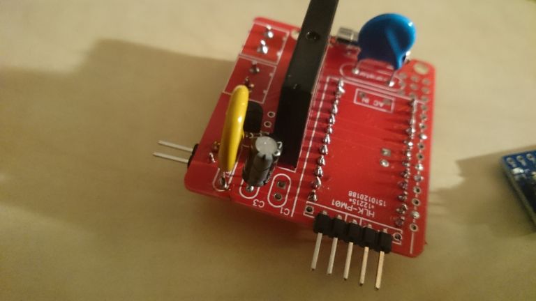
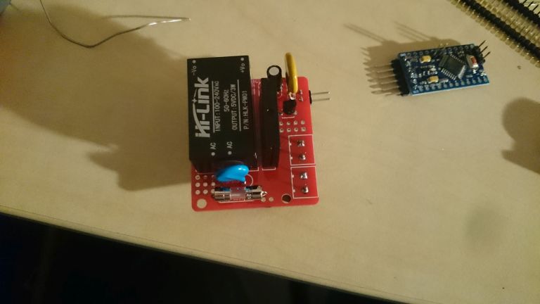
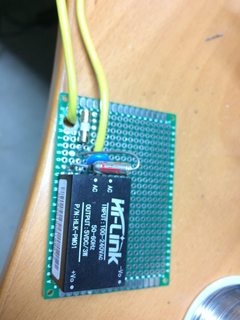
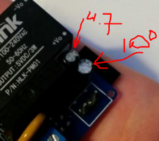
I still have trouble figuring out the C1 and C2. Here are some picture of my build so far.
Not sure all the components are placed correctly.C1 is placed with a small 100nf (104) but BOM in zip say's this is wrong.
As you can see i placed this one, cause the 100uf will not fit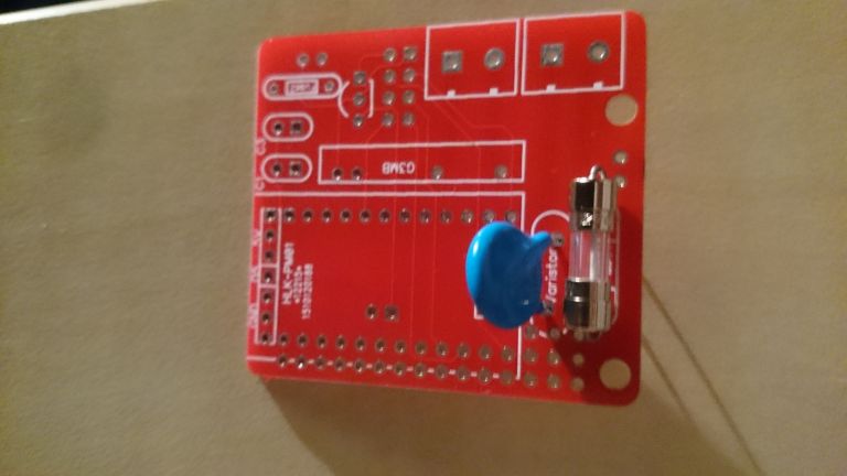
-
I still have trouble figuring out the C1 and C2. Here are some picture of my build so far.
Not sure all the components are placed correctly.C1 is placed with a small 100nf (104) but BOM in zip say's this is wrong.
As you can see i placed this one, cause the 100uf will not fit
-
So the regulator needs swapping about and the BOM cap values are incorrect from post (http://forum.mysensors.org/topic/1540/110v-230v-ac-to-mysensors-pcb-board/37) above that states :::
C1 100nF capacitor
C2 100uF capacitor
C3 4.7uF capacitor?
-
Hmmm. I got the 5.5V DC varistor from another AliExpress seller and I'm a bit puzzled as to why it starts smoking after a few seconds. Tried several of them. The HLK gives a solid 5V output. I'm assuming I got some lower voltage varistors by mistake?
-
So the regulator needs swapping about and the BOM cap values are incorrect from post (http://forum.mysensors.org/topic/1540/110v-230v-ac-to-mysensors-pcb-board/37) above that states :::
C1 100nF capacitor
C2 100uF capacitor
C3 4.7uF capacitor?
-
Hmmm. I got the 5.5V DC varistor from another AliExpress seller and I'm a bit puzzled as to why it starts smoking after a few seconds. Tried several of them. The HLK gives a solid 5V output. I'm assuming I got some lower voltage varistors by mistake?
@bjornhallberg Maybe I've missed reading something, but why use a varistor for 5 Vdc and not a zener diode?
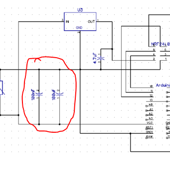 you can see that the two capacitors can be swapped without consequences