110v-230v AC to Mysensors PCB board
-
@bjornhallberg said:
I ordered some 5.1V and 5.6V 1206 SMD diodes
Just to remember, the typical zeners are 1W , which gives a max of 200mA of output capacity, pretty enough for Arduino+radio, but maybe not enough for many relays / Leds etc. And if they burn due overload, they will allow all voltage/current flowing from PSU into arduino.
That explains why we suggested the varistor, in order to short the PSU output and trigger its internal protection. Strange that your varistors didn't survive... Bad lot? Maybe they are not 5.5V as stated?
@rvendrame
No.
The zener will only lead current during over voltage condition and only needs to dissapate enough energy till one of your (multiple?) over current protection trips. Just as your varistor setup is supposed to work. -
@rvendrame
No.
The zener will only lead current during over voltage condition and only needs to dissapate enough energy till one of your (multiple?) over current protection trips. Just as your varistor setup is supposed to work.@m26872 , is it also true in case the PSU itself fail? And what happens if the circuit consumes more current than zener rating? I'm my (poor) knowledge, zeners are more relevant for stabilization, while varistor are effective 'protection' devices...
-
I spoke too soon... the unit seems to work well, but I hadn't tested if the relay actually switched or not. The status seems to change fine in the serial monitor, but it doesn't seem to be actually switching. I'll have to do some more troubleshooting.
-
@m26872 , is it also true in case the PSU itself fail? And what happens if the circuit consumes more current than zener rating? I'm my (poor) knowledge, zeners are more relevant for stabilization, while varistor are effective 'protection' devices...
@rvendrame
since we're discussing the PSU secondary side (output side), I think we already presume errors with the PSU. A fuse (over current protection) on the secondary is not just there as a back-up if the PSU internal over current protection fails. The fuse will also prevent your over voltage protection (zener, varistor, ...) from overload/burn/start a fire.The current from PSU to load will not pass through the zener and hence the rating is irrelevant from that perspective. In other applications where a zener is used as voltage regulator, the full load current will pass through the zener when in idleing and then the rating is critical.
-
@rvendrame
since we're discussing the PSU secondary side (output side), I think we already presume errors with the PSU. A fuse (over current protection) on the secondary is not just there as a back-up if the PSU internal over current protection fails. The fuse will also prevent your over voltage protection (zener, varistor, ...) from overload/burn/start a fire.The current from PSU to load will not pass through the zener and hence the rating is irrelevant from that perspective. In other applications where a zener is used as voltage regulator, the full load current will pass through the zener when in idleing and then the rating is critical.
@m26872 so how do we need to rate the zener? Should the zener be rated so that the fuse will blow before the zener brakes from the current it passes due to an over voltage situation? Or is it OK that the zener brakes to as long as it takes out the fuse first. Then an automatic fuse will no longer work.
-
@m26872 so how do we need to rate the zener? Should the zener be rated so that the fuse will blow before the zener brakes from the current it passes due to an over voltage situation? Or is it OK that the zener brakes to as long as it takes out the fuse first. Then an automatic fuse will no longer work.
@korttoma Good questions. As always a trade-off of risk, cost, space, taste, etc. They should already be answered in the varistor case though. Personally I think it's overkill with additional overvoltage protection at the low volt secondary side of a good quality PSU and an inexpensive load - fuse, capacitors and regulators should be more than enough. Focus should be the primary side protections.
Edit: Btw. Found some reading. See p.44
-
Just a quick post to confirm I got the relays working as well (with Domoticz). I didn't read the schematic at first and just assumed how the mains and relay external wiring should be done. Still no idea about the smoking varistor.
-
Just a quick post to confirm I got the relays working as well (with Domoticz). I didn't read the schematic at first and just assumed how the mains and relay external wiring should be done. Still no idea about the smoking varistor.
I thought all my relays were shot as I was not getting continuity on the load pins when I applied 5V. I checked resistance and there is just over 2K when 5V applied and infinite when none. I am going to put back together assuming the 240V A/C will pass through just fine.
-
The only thing between the HLK-PM01 and VCC is Fuse2. Check the Schematic. But yes a shorted varistor will in the combination with the fuse bring VCC to 0V. I experienced this also since the 5.5V varistors I bought from the link in the documentation (Ali seller Unionup Electronic Mall) did not work.
Seems like there is quite many of us that are having problems with the 5.5V varistors. I measured a few from my batch and they all show 0.4ohm with a multimeter, should they not have something like infinite resistance unless they get more then the 5.5V? My multimeter gives 0.6V when it measures resistance.
- Tomas
-
The only thing between the HLK-PM01 and VCC is Fuse2. Check the Schematic. But yes a shorted varistor will in the combination with the fuse bring VCC to 0V. I experienced this also since the 5.5V varistors I bought from the link in the documentation (Ali seller Unionup Electronic Mall) did not work.
Seems like there is quite many of us that are having problems with the 5.5V varistors. I measured a few from my batch and they all show 0.4ohm with a multimeter, should they not have something like infinite resistance unless they get more then the 5.5V? My multimeter gives 0.6V when it measures resistance.
@korttoma Say what...? You measure .4 ohms on your Varistor? I think you found your problem. :angry:
I have only ever used Varistor protection on the primary side, so I've got no experience with low voltage Varistors, but I don't think it should ever read .4.. Should be infinite.
-
Hello everyone,
Since we probably wanting this for multiple destinations, what if we used a centralized way at our home powerswitch.
We could stack multiple boards, and just use one arduino nano and one nRF on top of it. We just have to care about link each stack to a different arduino output.
Based in this idea we could create a second pcb for stack mounting, this board will just have the SSR and a deep switch for easy selectable arduino output. To make this ok we should connect each home powerswitch to each stack, another way exist if we use the main supply of the bottom board for all stacks, and place our circuit before our home power switch, but this is not recommendable.
For minimum stack size SSR should be horizontal mounted.
The advantages are obvious, just one arduino and nRF, one ac-dc and regulator for all home switches. Super low volume occupied and no more size constraints inside wall switches.
I don't have time to go forward and design this, so if someone wants it please go for it!! :smiley:
PS - Since we just use one arduino output per stack, we could avoid deep switch cost and configure by soldering selected track.
-
@BSoft I had this idea also and have been working on a pcb for some weeks now.
Its a 5x5 cm PCB you cut in halv so you get a 2 pcs which are 2.5x5cm - and they are stackable (like a shield).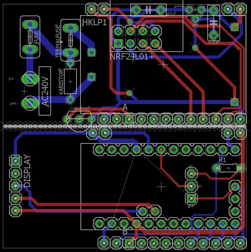
This is how i plan to stack them: (Blue inwall socket behind).
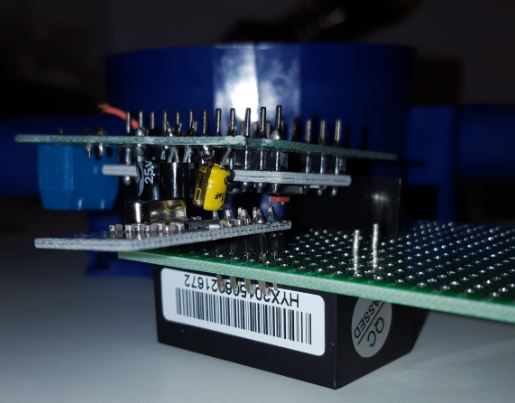
On the bottom you have the high power and HK 240->5v converter.
Then in the middle between the pcbs you have the radio and arduino and on top whatever you wants.
I have made outputs for LCD screen, buttons and/or motion.There are still much work in progress here but so far this is my thoughts... and it fits inside the typical wall hole.
This will not be ready for atleast some week, and the three weeks or so with order/deliver time.I will create my own post to get input on this when im done and If someone else knows and want to improve the design i can send over the files.
-
@sundberg84 Nice work with that sandwich!! :stuck_out_tongue:
Maybe you could move nrf24 to the other board to get away from ac-dc field and obtain better signal exposure.My idea is to move this node to my home powerswitch and control all my home lights, but as size isn't a problem maybe i'll use this:
http://www.dx.com/p/8-channel-5v-solid-state-relay-module-blue-black-green-250v-2a-213880 -
@mvdarend Thanks for the feedback! Happy to hear that it's working fine on your side as well. Although I do find it strange that the LE33 seems to be the other way around on your board? Maybe I just made a mistake with the silkscreen, and should the LE33 be on the bottom side? Anyway, I'll make sure to address this as soon as I possible (probably somewhere during next week). Sorry for the possible inconvenience, but thanks for pointing this out! :)
@sundberg84 The board dimension are about 4.2x4.7cm, so it is quite small. However, I'm afraid that because of the NRF24L01 module, and the 230v connections to it, it wouldn't really fit the box you have on that picture (assuming the board you have there is 5x5cm)..
Somewhere in the next week or 2 I'll try to design a custom 3d printable plastic box for the board that I've designed. Together with a 2-relay board as requested by @jemish .
@aproxx I'm a complete newbie but am interested in exploring this! Do you have a tutorial on the steps to populate this circuit board? I am comfortable with soldering but new to electronic circuits. Is there a particular order in which components ought to be soldered? Would you recommend breadboarding to begin with? Any sample code that can be used to do a sanity test?
Your guidance is greatly appreciated!
-
For those who wanted to see some pictures of the board:
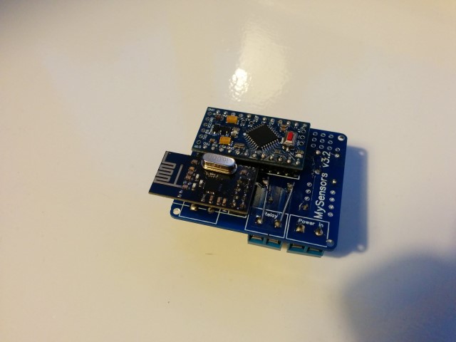
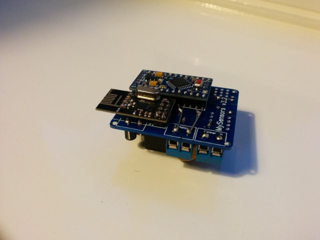
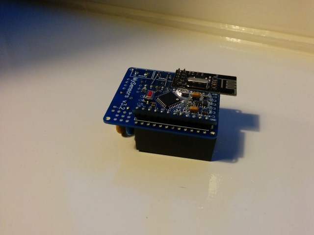
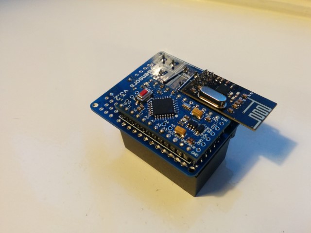
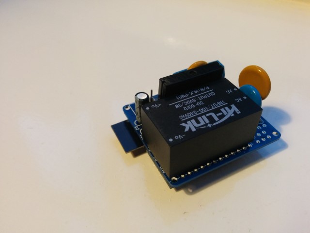
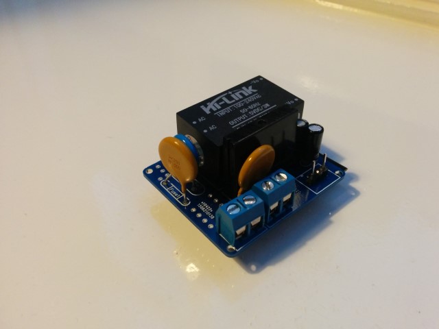
Small notice: These pictures are of a slightly older design. The newer design has a few minor changes like better component placement and a permanent fuse instead of this resettable fuse. But these pictures should at least give you an idea on how everything looks like, and shows how really small it actually is.
Also, I reinforced the traces of the 230v lines, which I absolutely recommend to do! (Although I do recommend to do it slightly more professional than I did on this prototype :)) -
Hi all,
**UPDATE April 17 2016 **
The latest version of this board is available HERE.After spending a few months on this forum and a few prototypes later, I decided I wanted to build a small but cheap PCB which could be placed in either the wall behind the light switch, or above the lamp.
Besides the boards I've seen on this forum, I wanted these boards to contain a module to go from 230v AC to 5/3.3v DC in order to power an Arduino nano and the NRF module. I eventually ended up with a PCB which is about 4 by 4.5cm. So with all components attached I'm hoping to get in stuffed in a 5x5x3cm plastic printed case.
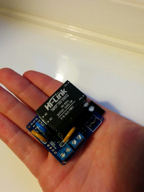
Modules which I've used to power the board:
[http://www.aliexpress.com/item/5-pcs-HLK-PM01-AC-DC-220V-to-5V-Step-Down-Power-Supply-Module-Intelligent-Household/32319202093.html?spm=2114.32010308.4.19.8oKfZgUPDATE: 2015/09/18
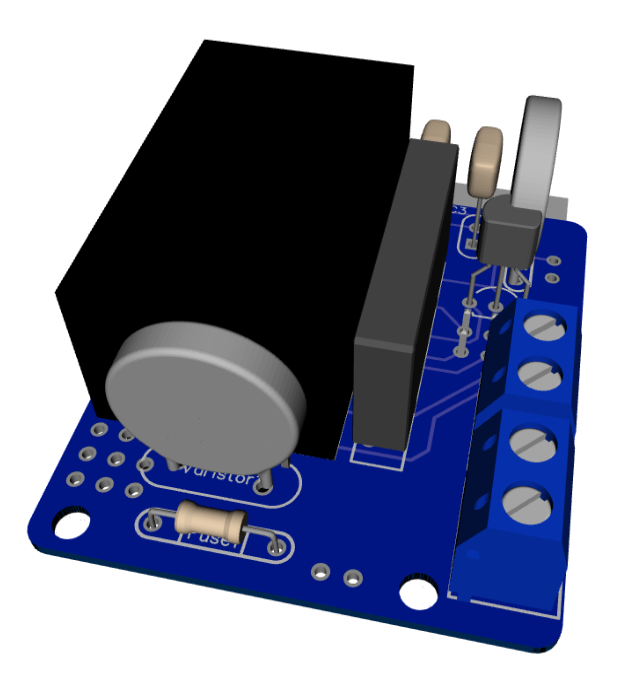
As promised, I've got an update for this project. The board has been tested in the past week, and everything is working as expected. Compared to the previous board I've posted, I have updated the following:
• Solder pads of LE33CZ have been placed a little wider apart to avoid short circuit while soldering.
• Solder pads of the resettable fuse (Fuse2) has been placed closer together to better fit the fuses of the BOM.
• Moved the NRF24L01 connector a bit away from the solid state relay. Should make it easier to solder.
• Moved Fuse2 to another location on the board, away from the 230v circuit.Some 3D pictures (Top and bottom):
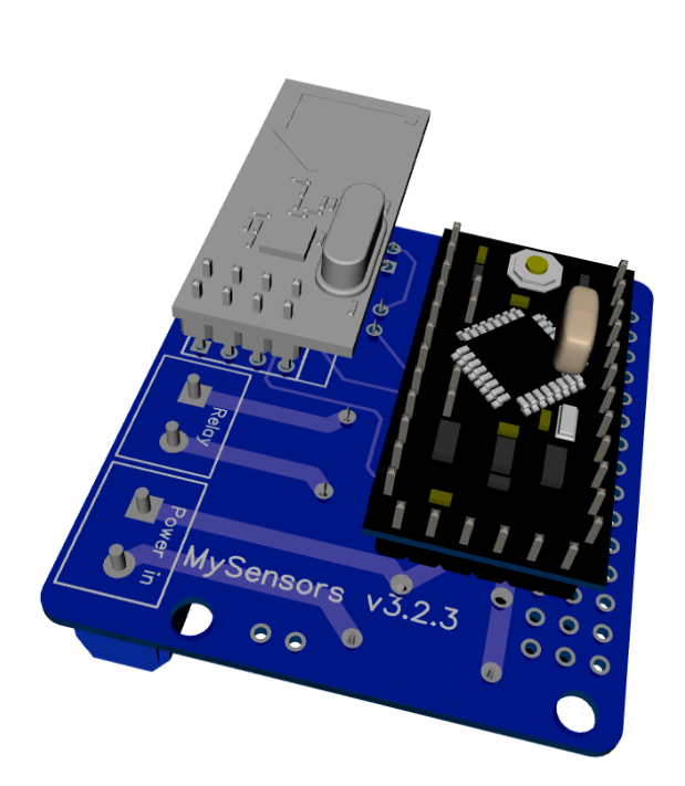
Anyone who is interested can order the PCB HERE
Some documentation, complete list of required components and all gerber / DipTrace files (in case you would like to make some modifications) can be found here: MySensors board v3.2.3.zip.
OK, this may be a really dumb question, but I need to ask, so please pardon my ignorance....
Clearly one main advantage of this is to control traditional light switches programatically and also through the standard light switch. How would I know whether someone flipped the light switch to turn on/off? How does the program "state" keep in sync with the "state" of the physical light switch?
Sorry again about what might be a rather dumb question.
-
You could connect the regular switch like a binary button, for example between D3 and Grd. The node could monitor both incoming messages from the controller and the state on D3.