Skip to content
  • MySensors
  • OpenHardware.io
  • Categories
  • Recent
  • Tags
  • Popular
Skins
  • Light
  • Brite
  • Cerulean
  • Cosmo
  • Flatly
  • Journal
  • Litera
  • Lumen
  • Lux
  • Materia
  • Minty
  • Morph
  • Pulse
  • Sandstone
  • Simplex
  • Sketchy
  • Spacelab
  • United
  • Yeti
  • Zephyr
  • Dark
  • Cyborg
  • Darkly
  • Quartz
  • Slate
  • Solar
  • Superhero
  • Vapor

  • Default (No Skin)
  • No Skin
Collapse
Brand Logo
  1. Home
  2. Hardware
  3. 110v-230v AC to Mysensors PCB board

110v-230v AC to Mysensors PCB board

Scheduled Pinned Locked Moved Hardware
269 Posts 63 Posters 270.9k Views 68 Watching
  • Oldest to Newest
  • Newest to Oldest
  • Most Votes
Reply
  • Reply as topic
Log in to reply
This topic has been deleted. Only users with topic management privileges can see it.
  • BSoftB Offline
    BSoftB Offline
    BSoft
    wrote on last edited by BSoft
    #137

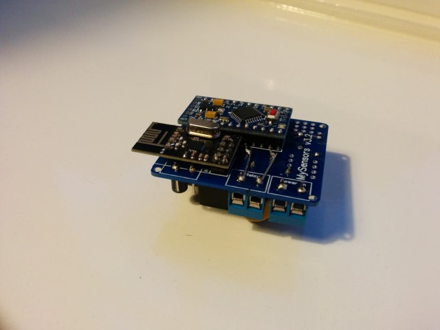
    @sundberg84 Nice work with that sandwich!! :stuck_out_tongue:
    Maybe you could move nrf24 to the other board to get away from ac-dc field and obtain better signal exposure.

    My idea is to move this node to my home powerswitch and control all my home lights, but as size isn't a problem maybe i'll use this:
    http://www.dx.com/p/8-channel-5v-solid-state-relay-module-blue-black-green-250v-2a-213880

    1 Reply Last reply
    0
    • A aproxx

      @mvdarend Thanks for the feedback! Happy to hear that it's working fine on your side as well. Although I do find it strange that the LE33 seems to be the other way around on your board? Maybe I just made a mistake with the silkscreen, and should the LE33 be on the bottom side? Anyway, I'll make sure to address this as soon as I possible (probably somewhere during next week). Sorry for the possible inconvenience, but thanks for pointing this out! :)

      @sundberg84 The board dimension are about 4.2x4.7cm, so it is quite small. However, I'm afraid that because of the NRF24L01 module, and the 230v connections to it, it wouldn't really fit the box you have on that picture (assuming the board you have there is 5x5cm)..

      Somewhere in the next week or 2 I'll try to design a custom 3d printable plastic box for the board that I've designed. Together with a 2-relay board as requested by @jemish .

      Z Offline
      Z Offline
      zebmina
      wrote on last edited by
      #138

      @aproxx I'm a complete newbie but am interested in exploring this! Do you have a tutorial on the steps to populate this circuit board? I am comfortable with soldering but new to electronic circuits. Is there a particular order in which components ought to be soldered? Would you recommend breadboarding to begin with? Any sample code that can be used to do a sanity test?

      Your guidance is greatly appreciated!

      1 Reply Last reply
      0
      • A aproxx

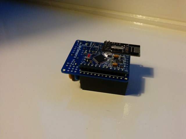
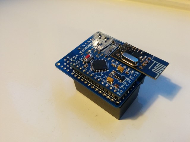
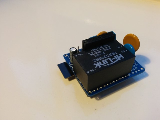
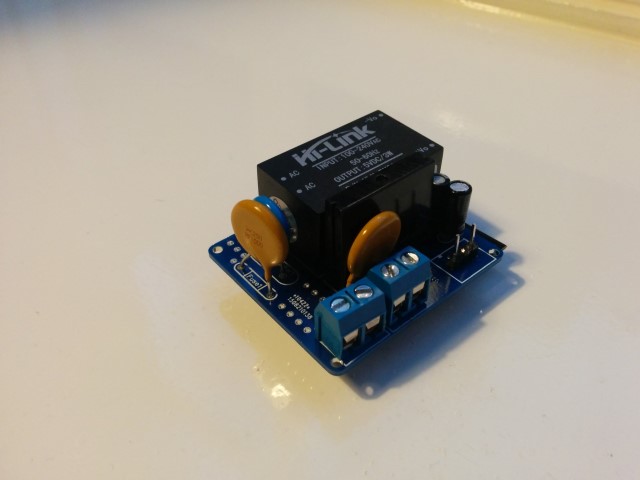
        For those who wanted to see some pictures of the board:
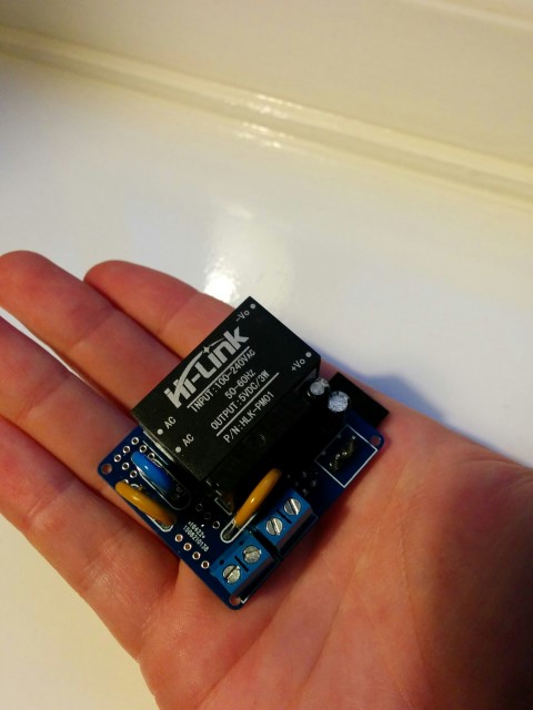
        IMG_20150921_194059 (Small).jpg IMG_20150921_194039 (Small).jpg IMG_20150921_194035 (Small).jpg IMG_20150921_194023 (Small).jpg IMG_20150921_192748 (Small).jpg IMG_20150921_192737 (Small).jpg IMG_20150921_192728 (Small).jpg

        Small notice: These pictures are of a slightly older design. The newer design has a few minor changes like better component placement and a permanent fuse instead of this resettable fuse. But these pictures should at least give you an idea on how everything looks like, and shows how really small it actually is.
        Also, I reinforced the traces of the 230v lines, which I absolutely recommend to do! (Although I do recommend to do it slightly more professional than I did on this prototype :))

        Z Offline
        Z Offline
        zebmina
        wrote on last edited by
        #139

        @aproxx Very nice! Just ordered.... But quite nervous - don't know much about electronic circuits, although I am quite good at following detailed instructions. You wouldn't happen to have a tutorial on how to populate the pcb?

        1 Reply Last reply
        0
        • A aproxx

          Hi all,

          **UPDATE April 17 2016 **
          The latest version of this board is available HERE.

          After spending a few months on this forum and a few prototypes later, I decided I wanted to build a small but cheap PCB which could be placed in either the wall behind the light switch, or above the lamp.

          Besides the boards I've seen on this forum, I wanted these boards to contain a module to go from 230v AC to 5/3.3v DC in order to power an Arduino nano and the NRF module. I eventually ended up with a PCB which is about 4 by 4.5cm. So with all components attached I'm hoping to get in stuffed in a 5x5x3cm plastic printed case.

          Modules which I've used to power the board:
          [http://www.aliexpress.com/item/5-pcs-HLK-PM01-AC-DC-220V-to-5V-Step-Down-Power-Supply-Module-Intelligent-Household/32319202093.html?spm=2114.32010308.4.19.8oKfZg

          UPDATE: 2015/09/18
          As promised, I've got an update for this project. The board has been tested in the past week, and everything is working as expected. Compared to the previous board I've posted, I have updated the following:
          • Solder pads of LE33CZ have been placed a little wider apart to avoid short circuit while soldering.
          • Solder pads of the resettable fuse (Fuse2) has been placed closer together to better fit the fuses of the BOM.
          • Moved the NRF24L01 connector a bit away from the solid state relay. Should make it easier to solder.
          • Moved Fuse2 to another location on the board, away from the 230v circuit.

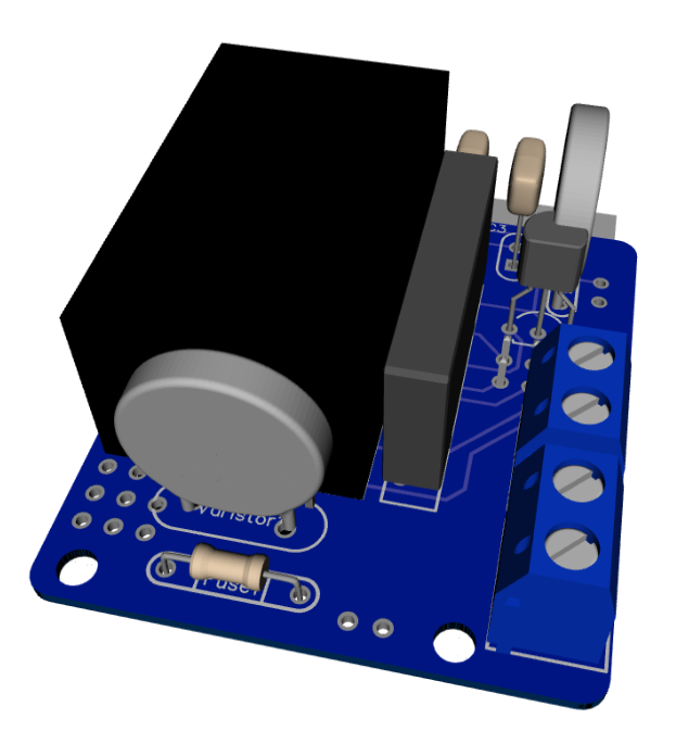
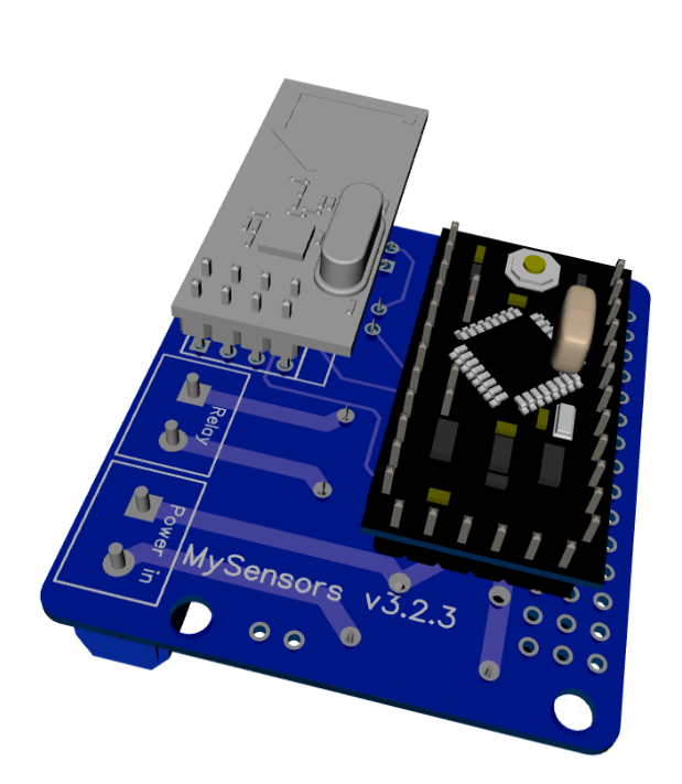
          Some 3D pictures (Top and bottom):
          Top.png
          Bottom.png

          Anyone who is interested can order the PCB HERE

          Some documentation, complete list of required components and all gerber / DipTrace files (in case you would like to make some modifications) can be found here: MySensors board v3.2.3.zip.

          Z Offline
          Z Offline
          zebmina
          wrote on last edited by
          #140

          OK, this may be a really dumb question, but I need to ask, so please pardon my ignorance....

          Clearly one main advantage of this is to control traditional light switches programatically and also through the standard light switch. How would I know whether someone flipped the light switch to turn on/off? How does the program "state" keep in sync with the "state" of the physical light switch?

          Sorry again about what might be a rather dumb question.

          1 Reply Last reply
          0
          • sundberg84S Offline
            sundberg84S Offline
            sundberg84
            Hardware Contributor
            wrote on last edited by
            #141

            You could connect the regular switch like a binary button, for example between D3 and Grd. The node could monitor both incoming messages from the controller and the state on D3.

            Controller: Proxmox VM - Home Assistant
            MySensors GW: Arduino Uno - W5100 Ethernet, Gw Shield Nrf24l01+ 2,4Ghz
            MySensors GW: Arduino Uno - Gw Shield RFM69, 433mhz
            RFLink GW - Arduino Mega + RFLink Shield, 433mhz

            1 Reply Last reply
            0
            • n3roN Offline
              n3roN Offline
              n3ro
              wrote on last edited by
              #142

              i hope i can buy this board in the near future =)

              pimatic + MySensors + Homeduino + z-way
              https://github.com/n3roGit/MySensors_n3ro

              1 Reply Last reply
              0
              • zrom69Z Offline
                zrom69Z Offline
                zrom69
                wrote on last edited by
                #143

                Hello
                I'm putting a home automation system I want to put in the cabinet
                electric power supply to power pc wholes my Arduino pro mini cable this method and these can be well card she could withstand power pc. thank you in advance for aid

                1 Reply Last reply
                0
                • RJ_MakeR RJ_Make

                  @korttoma Say what...? You measure .4 ohms on your Varistor? I think you found your problem. :angry:

                  I have only ever used Varistor protection on the primary side, so I've got no experience with low voltage Varistors, but I don't think it should ever read .4.. Should be infinite.

                  korttomaK Offline
                  korttomaK Offline
                  korttoma
                  Hero Member
                  wrote on last edited by
                  #144

                  @ServiceXp said:

                  @korttoma Say what...? You measure .4 ohms on your Varistor? I think you found your problem. :angry:

                  I have only ever used Varistor protection on the primary side, so I've got no experience with low voltage Varistors, but I don't think it should ever read .4.. Should be infinite.

                  I how received a new batch from another seller and these varistors show infinite resistance, unfortunately they are 0603 footprint so they are really tiny.

                  I bet the other seller (Unionup Electronic Mall) just sent me random crap because all of them show 0 resistance at first and then increase to 0.4 ohms, to bad it is too late to open dispute now. Just stay clear of Unionup Electronic Mall in the future.

                  • Tomas
                  RJ_MakeR 1 Reply Last reply
                  0
                  • Cliff KarlssonC Offline
                    Cliff KarlssonC Offline
                    Cliff Karlsson
                    wrote on last edited by Cliff Karlsson
                    #145

                    is it the brown or blue varistors that is defective?

                    Edit: sorry the brown ones are fuses

                    korttomaK 1 Reply Last reply
                    0
                    • Cliff KarlssonC Cliff Karlsson

                      is it the brown or blue varistors that is defective?

                      Edit: sorry the brown ones are fuses

                      korttomaK Offline
                      korttomaK Offline
                      korttoma
                      Hero Member
                      wrote on last edited by
                      #146

                      @Cliff-Karlsson the 5.5V SMD varistors I recieved from Aliexpress seller "Unionup Electronic Mall" do not work for me. Now running my circuit with out it instead.

                      • Tomas
                      1 Reply Last reply
                      0
                      • korttomaK korttoma

                        @ServiceXp said:

                        @korttoma Say what...? You measure .4 ohms on your Varistor? I think you found your problem. :angry:

                        I have only ever used Varistor protection on the primary side, so I've got no experience with low voltage Varistors, but I don't think it should ever read .4.. Should be infinite.

                        I how received a new batch from another seller and these varistors show infinite resistance, unfortunately they are 0603 footprint so they are really tiny.

                        I bet the other seller (Unionup Electronic Mall) just sent me random crap because all of them show 0 resistance at first and then increase to 0.4 ohms, to bad it is too late to open dispute now. Just stay clear of Unionup Electronic Mall in the future.

                        RJ_MakeR Offline
                        RJ_MakeR Offline
                        RJ_Make
                        Hero Member
                        wrote on last edited by
                        #147

                        @korttoma Thanks for the heads up on Unionup.

                        RJ_Make

                        1 Reply Last reply
                        0
                        • Cliff KarlssonC Offline
                          Cliff KarlssonC Offline
                          Cliff Karlsson
                          wrote on last edited by
                          #148

                          I don't have any ceramic capacitors. Can I replace them with regualr ones?

                          1 Reply Last reply
                          0
                          • Cliff KarlssonC Offline
                            Cliff KarlssonC Offline
                            Cliff Karlsson
                            wrote on last edited by
                            #149

                            Nevermind the capacitor question I found some ceramic capacitors now. But Is the "BOM" that shows component placement in the beginning of the thread accurate? only the transistor needs to be turned around?

                            1 Reply Last reply
                            0
                            • Cliff KarlssonC Offline
                              Cliff KarlssonC Offline
                              Cliff Karlsson
                              wrote on last edited by
                              #150

                              @bjornhallberg said:

                              @m26872 You're probably right, I just followed the BOM. I'll see if I

                              I think the first post should be edited with the right components. In the doc it says

                              100nF + 100pF Capacitors 0.02 Euro AliExpress Link

                              but in the post is says:C2 100uF capacitor

                              I have a couple of 100uF 16v but I guess that wont work, correct?

                              1 Reply Last reply
                              0
                              • Cliff KarlssonC Offline
                                Cliff KarlssonC Offline
                                Cliff Karlsson
                                wrote on last edited by
                                #151

                                Sorry for spamming but regarding fuse 2. Can someone post a link to a fuse that works well. I got alot of those brown PTC fuses but the holes in the PCB are too small. I tried drilling them up but then I got no contact so I had to solder a separate separate wire from 5v to the fuse to get any power to the arduino and the rest of the components.

                                Or has there been a mistake on my PCB with too small holes for fuse 2?

                                korttomaK 1 Reply Last reply
                                0
                                • Cliff KarlssonC Cliff Karlsson

                                  Sorry for spamming but regarding fuse 2. Can someone post a link to a fuse that works well. I got alot of those brown PTC fuses but the holes in the PCB are too small. I tried drilling them up but then I got no contact so I had to solder a separate separate wire from 5v to the fuse to get any power to the arduino and the rest of the components.

                                  Or has there been a mistake on my PCB with too small holes for fuse 2?

                                  korttomaK Offline
                                  korttomaK Offline
                                  korttoma
                                  Hero Member
                                  wrote on last edited by korttoma
                                  #152

                                  @Cliff-Karlsson the holes for Fuse2 are to smal and this has been mentioned a few times before in this thread. I drilled mine out with a 0.8mm drill and could then use the recommended fuse without any extra wires.

                                  • Tomas
                                  1 Reply Last reply
                                  0
                                  • T Offline
                                    T Offline
                                    tomkxy
                                    wrote on last edited by
                                    #153

                                    Since the 5.5V varistor is not available from the linked AliExpress shop I wonder whether this varistor would work as well?
                                    https://www.conrad.de/de/smd-varistor-we-vs-82537040-4-v-wuerth-elektronik-we-vs-82537040-1-st-1086820.html

                                    1 Reply Last reply
                                    0
                                    • zrom69Z Offline
                                      zrom69Z Offline
                                      zrom69
                                      wrote on last edited by
                                      #154

                                      greeted everyone
                                      look what concerns island link tests on this HLK-PM01
                                      http://lygte-info.dk/review/Power Mains to 5V 0.6A Hi-Link HLK-PM01 UK.html

                                      1 Reply Last reply
                                      0
                                      • S Offline
                                        S Offline
                                        sebas
                                        wrote on last edited by
                                        #155

                                        A question about the fuses. The BOM in the Word document links to two 230V fuses, the PTC and slow blow fuse. If I read the schematic correctly one fuse is on the AC side and one is on the DC side. How does a 230V fuse help on the DC side where there should not be more than 5Vdc? Or am I missing something? As I'm quite new to this I'm probably not reading the schematic correctly or missing something :-)

                                        1 Reply Last reply
                                        0
                                        • A aproxx

                                          For those who wanted to see some pictures of the board:
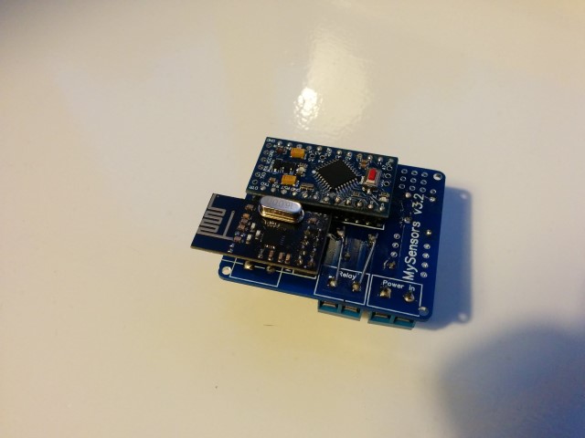
                                          IMG_20150921_194059 (Small).jpg IMG_20150921_194039 (Small).jpg IMG_20150921_194035 (Small).jpg IMG_20150921_194023 (Small).jpg IMG_20150921_192748 (Small).jpg IMG_20150921_192737 (Small).jpg IMG_20150921_192728 (Small).jpg

                                          Small notice: These pictures are of a slightly older design. The newer design has a few minor changes like better component placement and a permanent fuse instead of this resettable fuse. But these pictures should at least give you an idea on how everything looks like, and shows how really small it actually is.
                                          Also, I reinforced the traces of the 230v lines, which I absolutely recommend to do! (Although I do recommend to do it slightly more professional than I did on this prototype :))

                                          the cosmic gateT Offline
                                          the cosmic gateT Offline
                                          the cosmic gate
                                          wrote on last edited by
                                          #156

                                          @aproxx said:

                                          For those who wanted to see some pictures of the board:
                                          IMG_20150921_194059 (Small).jpg IMG_20150921_194039 (Small).jpg IMG_20150921_194035 (Small).jpg IMG_20150921_194023 (Small).jpg IMG_20150921_192748 (Small).jpg IMG_20150921_192737 (Small).jpg IMG_20150921_192728 (Small).jpg

                                          Small notice: These pictures are of a slightly older design. The newer design has a few minor changes like better component placement and a permanent fuse instead of this resettable fuse. But these pictures should at least give you an idea on how everything looks like, and shows how really small it actually is.
                                          Also, I reinforced the traces of the 230v lines, which I absolutely recommend to do! (Although I do recommend to do it slightly more professional than I did on this prototype :))

                                          I really like this design, but it would be even nicer when this fits a ESP8266 :) Maybe the PCB could be even smaller . And it works together with link text .
                                          So is there maybe one of the PCB designer guys who can build /draw / design this 230v to ESP8266 PCB ?

                                          There's more than meets the eye

                                          1 Reply Last reply
                                          2
                                          Reply
                                          • Reply as topic
                                          Log in to reply
                                          • Oldest to Newest
                                          • Newest to Oldest
                                          • Most Votes


                                          16

                                          Online

                                          11.7k

                                          Users

                                          11.2k

                                          Topics

                                          113.0k

                                          Posts


                                          Copyright 2019 TBD   |   Forum Guidelines   |   Privacy Policy   |   Terms of Service
                                          • Login

                                          • Don't have an account? Register

                                          • Login or register to search.
                                          • First post
                                            Last post
                                          0
                                          • MySensors
                                          • OpenHardware.io
                                          • Categories
                                          • Recent
                                          • Tags
                                          • Popular