110v-230v AC to Mysensors PCB board
-
Sorry for spamming but regarding fuse 2. Can someone post a link to a fuse that works well. I got alot of those brown PTC fuses but the holes in the PCB are too small. I tried drilling them up but then I got no contact so I had to solder a separate separate wire from 5v to the fuse to get any power to the arduino and the rest of the components.
Or has there been a mistake on my PCB with too small holes for fuse 2?
@Cliff-Karlsson the holes for Fuse2 are to smal and this has been mentioned a few times before in this thread. I drilled mine out with a 0.8mm drill and could then use the recommended fuse without any extra wires.
-
Since the 5.5V varistor is not available from the linked AliExpress shop I wonder whether this varistor would work as well?
https://www.conrad.de/de/smd-varistor-we-vs-82537040-4-v-wuerth-elektronik-we-vs-82537040-1-st-1086820.html -
greeted everyone
look what concerns island link tests on this HLK-PM01
http://lygte-info.dk/review/Power Mains to 5V 0.6A Hi-Link HLK-PM01 UK.html -
A question about the fuses. The BOM in the Word document links to two 230V fuses, the PTC and slow blow fuse. If I read the schematic correctly one fuse is on the AC side and one is on the DC side. How does a 230V fuse help on the DC side where there should not be more than 5Vdc? Or am I missing something? As I'm quite new to this I'm probably not reading the schematic correctly or missing something :-)
-
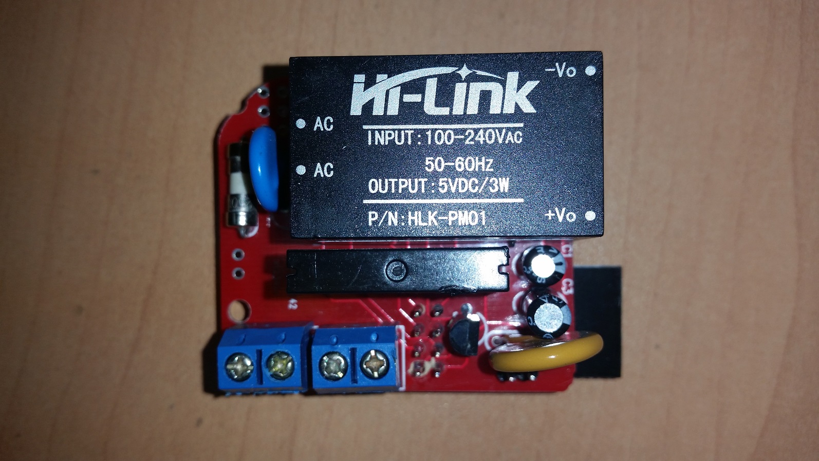
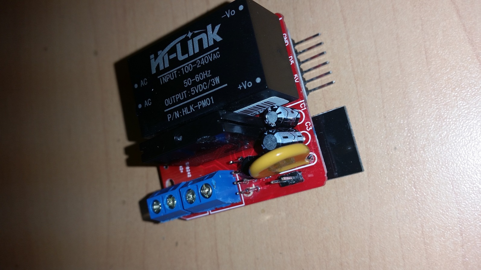
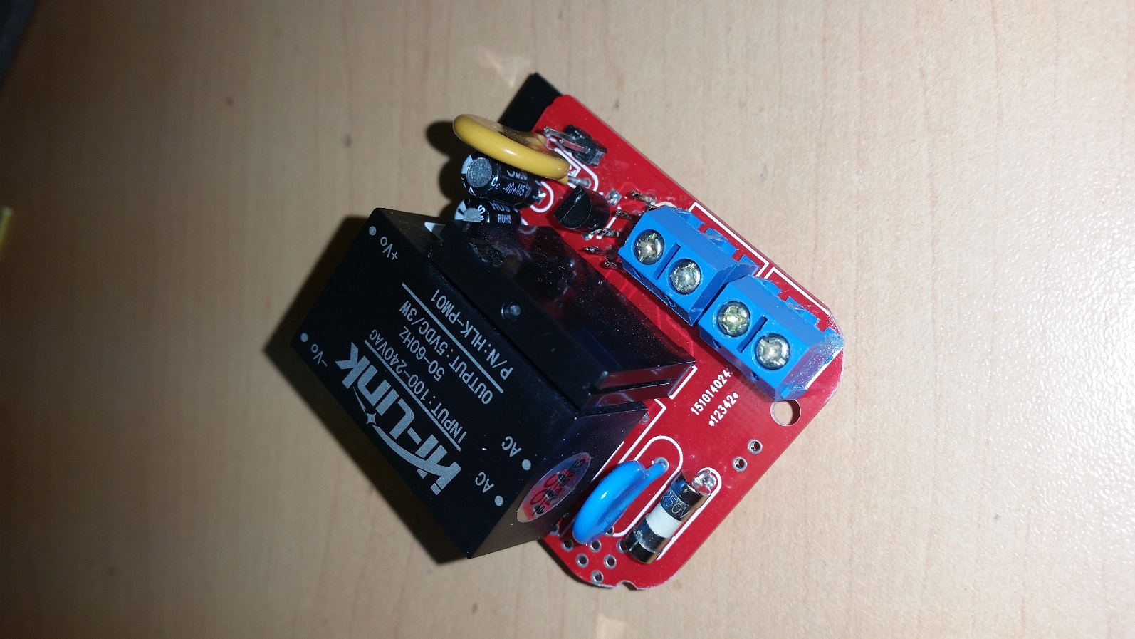
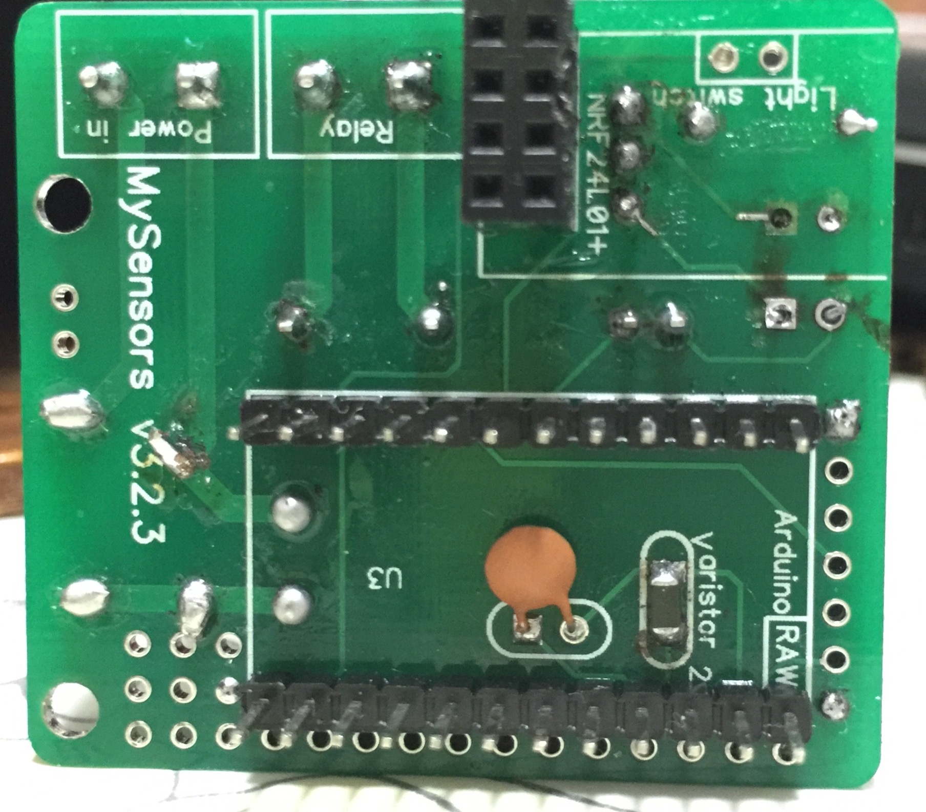
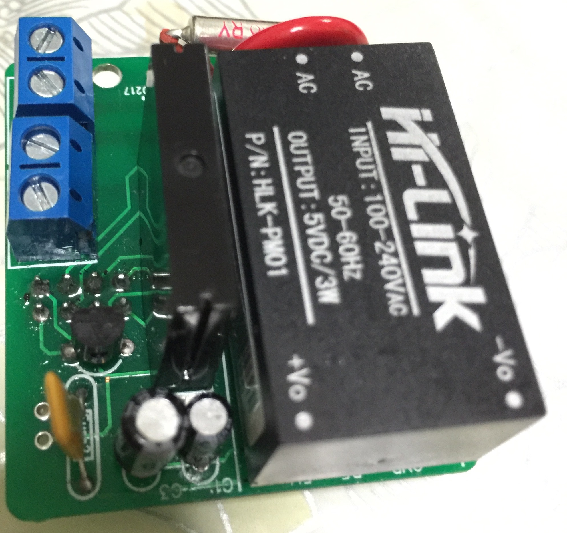
For those who wanted to see some pictures of the board:
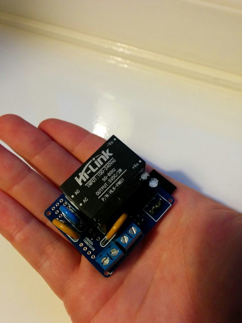
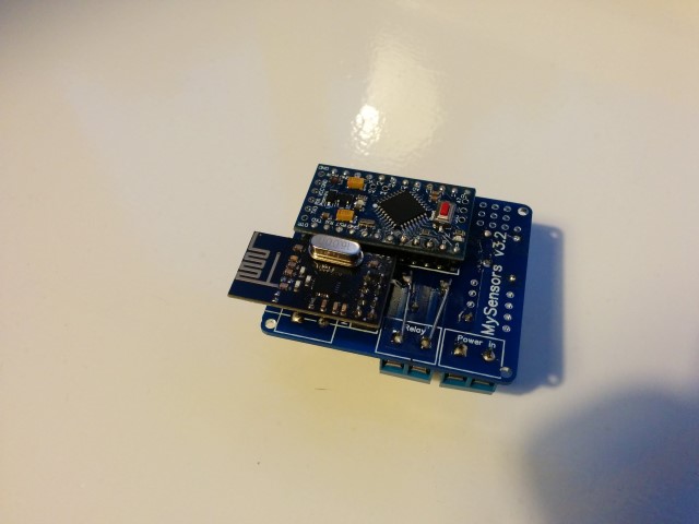
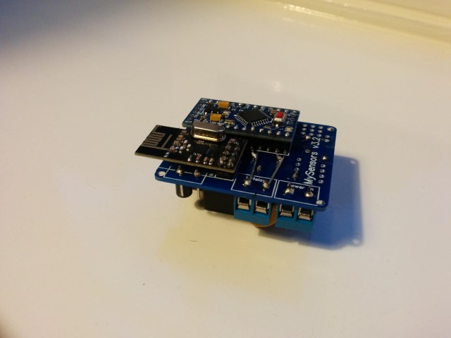
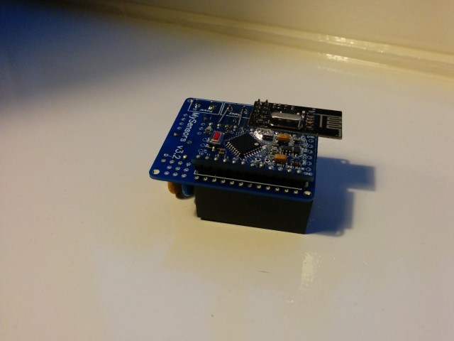
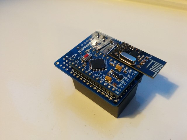
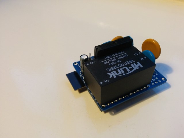
Small notice: These pictures are of a slightly older design. The newer design has a few minor changes like better component placement and a permanent fuse instead of this resettable fuse. But these pictures should at least give you an idea on how everything looks like, and shows how really small it actually is.
Also, I reinforced the traces of the 230v lines, which I absolutely recommend to do! (Although I do recommend to do it slightly more professional than I did on this prototype :))@aproxx said:
For those who wanted to see some pictures of the board:
Small notice: These pictures are of a slightly older design. The newer design has a few minor changes like better component placement and a permanent fuse instead of this resettable fuse. But these pictures should at least give you an idea on how everything looks like, and shows how really small it actually is.
Also, I reinforced the traces of the 230v lines, which I absolutely recommend to do! (Although I do recommend to do it slightly more professional than I did on this prototype :))I really like this design, but it would be even nicer when this fits a ESP8266 :) Maybe the PCB could be even smaller . And it works together with link text .
So is there maybe one of the PCB designer guys who can build /draw / design this 230v to ESP8266 PCB ? -
WOW, REALLY GREAT JOB!
-
Hello everyone,
This is a gr8 project, i am looking forward to make few sensor for my home. As i don't have any experience with electronics and very new to all these terms and components.
I would request anyone of you to, kindly post some pictures of the board with components in place that i can copy and make my boards.
**Specially 3 pin regulator and Capacitors **My first assembled board is not working, it looks like m doing something wrong with either the capacitors or the regulator. I checked my NRF24l01 VCC pin and not getting any voltage at all.
Please help me guys......
Thanks and Regards
Brij -
Hello everyone,
This is a gr8 project, i am looking forward to make few sensor for my home. As i don't have any experience with electronics and very new to all these terms and components.
I would request anyone of you to, kindly post some pictures of the board with components in place that i can copy and make my boards.
**Specially 3 pin regulator and Capacitors **My first assembled board is not working, it looks like m doing something wrong with either the capacitors or the regulator. I checked my NRF24l01 VCC pin and not getting any voltage at all.
Please help me guys......
Thanks and Regards
Brij@Brijesh-Mishra said:
I would request anyone of you to, kindly post some pictures of the board with components in place that i can copy and make my boards.
@the-cosmic-gate has already posted images above.
Perhaps you should post a picture of what you've done?
-
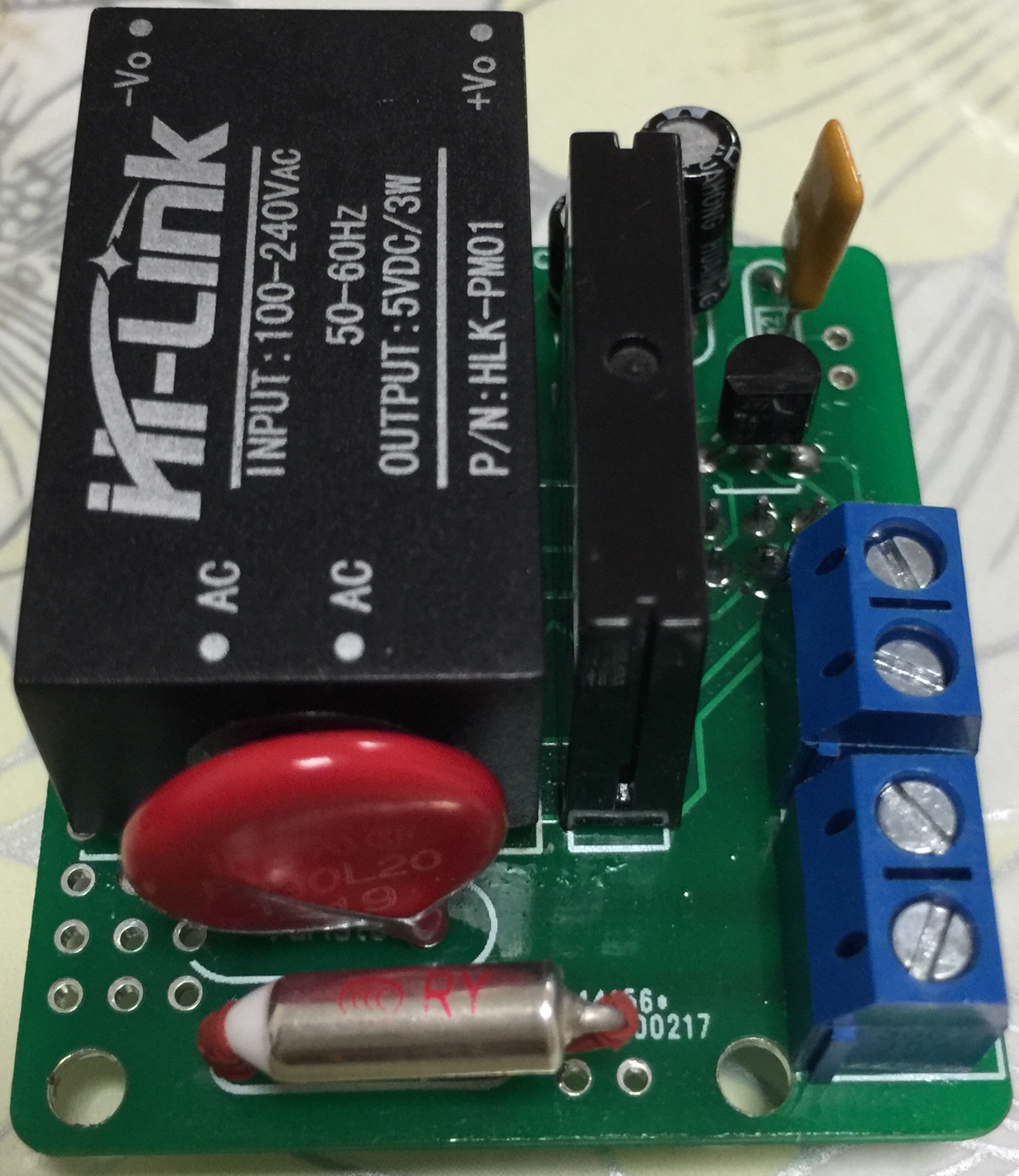
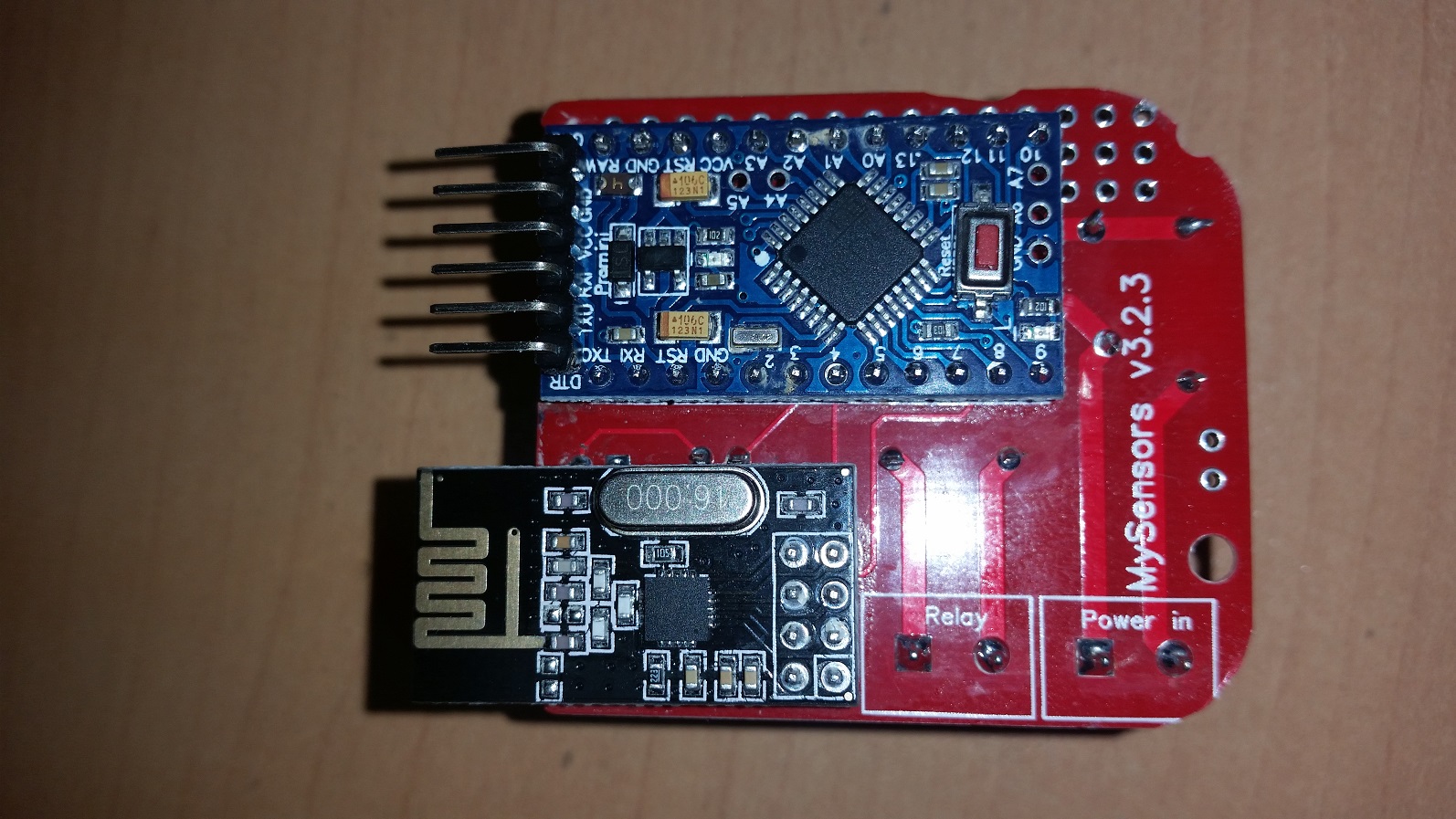
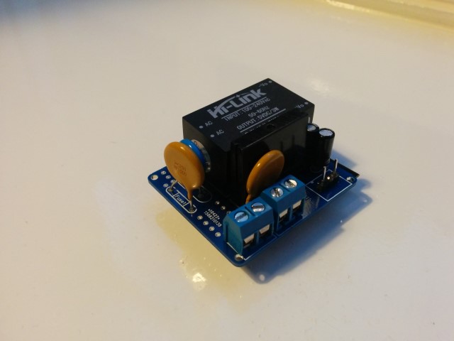
Thanks a lot for your response, this is what i have done so far.
-
Could I ask to the smart PCB builder's / designers to make the same 230v PCB but not using an Arduino but one of the ESP8266 versions , the the board could be even smaller and easier to fix in the wholes
-
Could I ask to the smart PCB builder's / designers to make the same 230v PCB but not using an Arduino but one of the ESP8266 versions , the the board could be even smaller and easier to fix in the wholes
@the-cosmic-gate, greetings to you. Kindly let me know, is there any issue with the component placement in the board. Not sure why it's not working :(.
Thanks
Brijesh -
@aproxx Great job. Just started to work with mysensors and I was looking for a power supply alternative to mobile phone chargers. Though one question; the board that you included the relay was really interesting. Why did you not proceed on this? Also, do you sell the PCB's?
-
@the-cosmic-gate, greetings to you. Kindly let me know, is there any issue with the component placement in the board. Not sure why it's not working :(.
Thanks
Brijesh@Brijesh-Mishra said:
@the-cosmic-gate, greetings to you. Kindly let me know, is there any issue with the component placement in the board. Not sure why it's not working :(.
Thanks
Brijesh
There absolutely nothing wrong, but I want to use the ESP8266 to build in instead of the arduino and 2.4 ghz radio (the ESP8266 is an Arduino incl WiFi) so the PCB can be much smaller I think.
-
@Brijesh-Mishra , I see two issues with your photos. 1) the 3.3V regulator is on backwards. If you earlier in this thread someone comments that the regulator needs to be put on backward. The white design on the board is not correct. That was also my experience with the boards I built. The flat side of the regulator should face the two cap's. 2) more importantly, it appears that you used a thermal fuse in the spot where fuse #1 goes. Fuse #1 is supposed to be a 300ma slo blow fuse. If that is what you have there no problem, but it looks like the thermal discussed in the thread. This board does not have a place for the thermal fuse. I would consider this a serious safety issue, but I am not an expert. Hope this helps.
@novicit, Thanks a lot for your help. i will make a new board as per your guidance and share the photos soon.
Regards
Brijesh -
-
Hi,
I now received PCBs from DirtyPCB. I'm searching components (but not from China sellers).
Can I use this varistor on the AC side?: http://uk.farnell.com/multicomp/mcsr391k10ds/varistor-60j-250vrms/dp/1856880
And on the DC side?: http://uk.farnell.com/multicomp/mcvz1206m050agt/varistor-multilayer-4vac-0402/dp/2462756Thanks in advance!