
110v-230v AC to Mysensors PCB board
-
@aproxx will the second relay be opt-in?
I mean, will the board function normally with only one relay?@Sefi-Ninio
Yes, it will be perfectly possible to just install 1 relay on the board and it will still work fine.
More news in the next few days! ;) -
-
-
-
The latest version of this board is available here!
Because of the large number of request a second (optional) solid state relay has been added to the board. Enjoy! -
@jemish
It's on the middle of the board on the top side. 4 pins are present to use as switch inputs. 2 pins are ground, and then pin 4 and 7 are available as well.
By closing the connection between pin 4 and ground you will switch te status of relay 1. When closing the connection between ground and pin 7 you'll switch the status of relay 2. -
Hi all,
**UPDATE April 17 2016 **
The latest version of this board is available HERE.After spending a few months on this forum and a few prototypes later, I decided I wanted to build a small but cheap PCB which could be placed in either the wall behind the light switch, or above the lamp.
Besides the boards I've seen on this forum, I wanted these boards to contain a module to go from 230v AC to 5/3.3v DC in order to power an Arduino nano and the NRF module. I eventually ended up with a PCB which is about 4 by 4.5cm. So with all components attached I'm hoping to get in stuffed in a 5x5x3cm plastic printed case.
Modules which I've used to power the board:
[http://www.aliexpress.com/item/5-pcs-HLK-PM01-AC-DC-220V-to-5V-Step-Down-Power-Supply-Module-Intelligent-Household/32319202093.html?spm=2114.32010308.4.19.8oKfZgUPDATE: 2015/09/18
As promised, I've got an update for this project. The board has been tested in the past week, and everything is working as expected. Compared to the previous board I've posted, I have updated the following:
• Solder pads of LE33CZ have been placed a little wider apart to avoid short circuit while soldering.
• Solder pads of the resettable fuse (Fuse2) has been placed closer together to better fit the fuses of the BOM.
• Moved the NRF24L01 connector a bit away from the solid state relay. Should make it easier to solder.
• Moved Fuse2 to another location on the board, away from the 230v circuit.Some 3D pictures (Top and bottom):
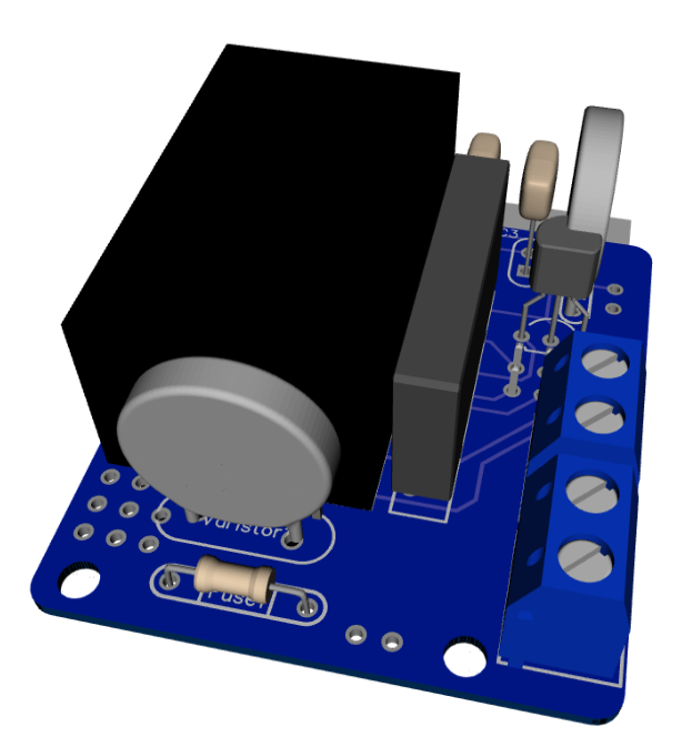
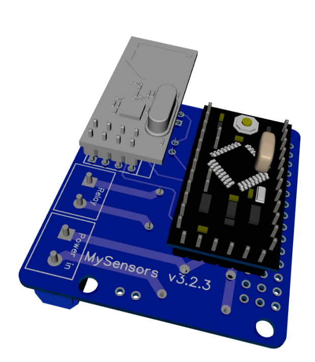
Anyone who is interested can order the PCB HERE
Some documentation, complete list of required components and all gerber / DipTrace files (in case you would like to make some modifications) can be found here: MySensors board v3.2.3.zip.
@aproxx I have a few left-over boards from the earlier release - where the holes for fuse2 were smaller than required (PTC Resettable Fuses 250V 1A TRF250-1000 PPTC Polymeric PTC PolySwitch). I wanted to use up the remaining boards, and wondering if the following fuse could be a substitute (USA-based, leads are smaller diameter and would fit the holes) - MF-R110 FUSE PTC RESETTABLE 1.10A HOLD MF-R110 110 MF.
Thanks for your guidance.
-
-
@Fat-Fly these tiny boards have really bad isolation and are dangerous tu use.
And did you have a look at this 1-diode "rectifier" ? The ripple is probably awful and the result will affect the quality of the radio transmission.
Saving 0.5$ compared to an HLK is really not worth it ! -
@bruno tanke you, very good.
I share it in facebook.


Hello! It looks like you're interested in this conversation, but you don't have an account yet.
Getting fed up of having to scroll through the same posts each visit? When you register for an account, you'll always come back to exactly where you were before, and choose to be notified of new replies (either via email, or push notification). You'll also be able to save bookmarks and upvote posts to show your appreciation to other community members.
With your input, this post could be even better 💗
Register Login