110v-230v AC to Mysensors PCB board
-
As promised: In the attachment of this post you can find all required information to build this board.
The zip file includes all required Gerber files, bill of materials, as well as the Schematic and PCB design (drawn using DipTrace).One remark: I've slightly adjusted the design to optimize the reception for the NRF24L01. The antenna of this chip is now placed slightly next to the custom PCB. Hopefully this will result in a better RF reception.
Size is approximately 47 by 42mm.Download (Please be aware that this board is still untested at this moment, so please doublecheck things yourself before ordering!):
Check latest post for updated version. -
@approxx: nice board!
could I give you one or two tips? as I have recently designed an ac board too...there is one or two trace which are 90° corner. maybe I am a little old school on this but it is preferable to have 45°. but it should work I think no problem.
Your board will not draw too much AC current I think, and I don't know what are your trace widths for AC. but you can check here http://circuitcalculator.com/wordpress/2006/01/31/pcb-trace-width-calculator/ if you want to know width of trace regarding current flow. Then if you can't have the right width because of space... you can use soldermask layer stop and then you will be able to add soldering on all the AC trace and give it more strength for more current drawing. Because most of china fabhouse use 1oz copper. Some 2oz but more expensive.Just my 2cent tip, maybe you already know it, and have already ordered you board.
-
@scalz Yeah usually I'm going for 45 degree angles as well, but I guess I just forgot for those few. However I do have full confidence in Dirty PCBs, so I'm sure there wouldn't be any disruptions in the trace.
Regarding trace thickness/width: I've been doing some calculations as well, but with 1oz copper traces I would need extremely wide traces to come up with a decent copper volume. So my plan is to solder a thin wire at the bottom side of the PCB between the AC connection points. That's why I've got the AC and 5v DC circuits separated as much as possible. :)
But thanks for the feedback anyway! And congrats on taking the first step of ordering the board! I'll be doing the same tomorrow.
-
Looking at your pcbs and looking the same time on my badly soldered dimmer.. i have the gut feeling i should maybe redo this with a proper pcb. :sweat_smile:
-
@DrJeff said:
Just Kidding I need to get my dimmers working properly also. You got the zerocross working right? 220v 110v? share sketch? will yours work locally with gateway off?
Yes the zerocrossing is working right. Shouldn't working with gateway off only be a matter of programming? ^^
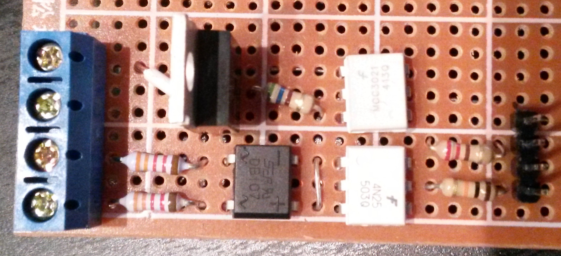
Built vor 220V, but should also run at 110V (with different resistors), need to check the specifications of the combonents again to verify that.I got no working MySensors sketch or a drawn pcb layout yet, but i can describe how it works.
Left connectors are (up to down): LOAD: Phase, Neutral; Source: Neutral, Phase
Right connectors are (up to down): GND, PWM Output, Zero-Crossing Input, VCCThe Zerocrossing detection is done by the bridge rectifier and the zerocrossing detection module 4N25.
The Signal goes to a INT-Pin of an arduino.In a test sketch i use a timer and the interrupt to do the correct pwm output.
The pwm output goes to the MOC3021 (Opto) that will fire the TRIAC seen left from it.Little test sketch:
#include <TimerOne.h> //Config int INTPin = 0; int outputPin = 11; int dimLevel = 64; // Dim level (0(on)-128(off)) int freqStep = 75; //50Hz, should be 65 for 60Hz //Global volatile int i=0; // Counter. Only fire if i >= dimLevel volatile boolean zeroCross=0; void setup() { pinMode(outputPin, OUTPUT); attachInterrupt(INTPin, zero_cross_detect, RISING); Timer1.initialize(freqStep); Timer1.attachInterrupt(dim_check, freqStep); } void zero_cross_detect() { zeroCross = true; i=0; digitalWrite(outputPin, LOW); } void dim_check() { if(zeroCross == true) { if(i>=dimLevel) { digitalWrite(outputPin, HIGH); i=0; zeroCross = false; } else { i++; } } } void loop() { } -
@scalz Yeah usually I'm going for 45 degree angles as well, but I guess I just forgot for those few. However I do have full confidence in Dirty PCBs, so I'm sure there wouldn't be any disruptions in the trace.
Regarding trace thickness/width: I've been doing some calculations as well, but with 1oz copper traces I would need extremely wide traces to come up with a decent copper volume. So my plan is to solder a thin wire at the bottom side of the PCB between the AC connection points. That's why I've got the AC and 5v DC circuits separated as much as possible. :)
But thanks for the feedback anyway! And congrats on taking the first step of ordering the board! I'll be doing the same tomorrow.
-
@jemish I've made some minor changes to the board (nothing functional has been changed, just some updated silk screen and modified the 90 degree angles to 45 degree angles.)
Please be aware that at this moment the board still isn't confirmed to be working. If you want to be 100% sure everything works properly, I strongly advise to wait for another 5-7 weeks. That way I can assemble the board myself and confirm everything is working as expected.
-
@DrJeff said:
Just Kidding I need to get my dimmers working properly also. You got the zerocross working right? 220v 110v? share sketch? will yours work locally with gateway off?
Yes the zerocrossing is working right. Shouldn't working with gateway off only be a matter of programming? ^^
Built vor 220V, but should also run at 110V (with different resistors), need to check the specifications of the combonents again to verify that.I got no working MySensors sketch or a drawn pcb layout yet, but i can describe how it works.
Left connectors are (up to down): LOAD: Phase, Neutral; Source: Neutral, Phase
Right connectors are (up to down): GND, PWM Output, Zero-Crossing Input, VCCThe Zerocrossing detection is done by the bridge rectifier and the zerocrossing detection module 4N25.
The Signal goes to a INT-Pin of an arduino.In a test sketch i use a timer and the interrupt to do the correct pwm output.
The pwm output goes to the MOC3021 (Opto) that will fire the TRIAC seen left from it.Little test sketch:
#include <TimerOne.h> //Config int INTPin = 0; int outputPin = 11; int dimLevel = 64; // Dim level (0(on)-128(off)) int freqStep = 75; //50Hz, should be 65 for 60Hz //Global volatile int i=0; // Counter. Only fire if i >= dimLevel volatile boolean zeroCross=0; void setup() { pinMode(outputPin, OUTPUT); attachInterrupt(INTPin, zero_cross_detect, RISING); Timer1.initialize(freqStep); Timer1.attachInterrupt(dim_check, freqStep); } void zero_cross_detect() { zeroCross = true; i=0; digitalWrite(outputPin, LOW); } void dim_check() { if(zeroCross == true) { if(i>=dimLevel) { digitalWrite(outputPin, HIGH); i=0; zeroCross = false; } else { i++; } } } void loop() { } -
@jemish I've made some minor changes to the board (nothing functional has been changed, just some updated silk screen and modified the 90 degree angles to 45 degree angles.)
Please be aware that at this moment the board still isn't confirmed to be working. If you want to be 100% sure everything works properly, I strongly advise to wait for another 5-7 weeks. That way I can assemble the board myself and confirm everything is working as expected.
-
@jemish
All components are at my desk at the moment. The only thing missing is.. The PCB itself. :)
DirtyPCBs' website states that the board was shipped to me at August 24. My packets from China usually arrive about 2 or 3 weeks after they have been sent from China, so I expect it to arrive somewhere next week.
After the boards have arrived I'll make sure to have it assembled in less than a week. :) -
I received the newly designed PCB last weekend, and have been soldering/testing the board since it arrived. Just a few minor changes to the layout (not the schematic) and the board should be completely finished! So far the results look promising.
@jemish: I'm currently re-working the design a bit and working on documentation, but I'll make sure to post the new and completely finished design by the end of the week! -
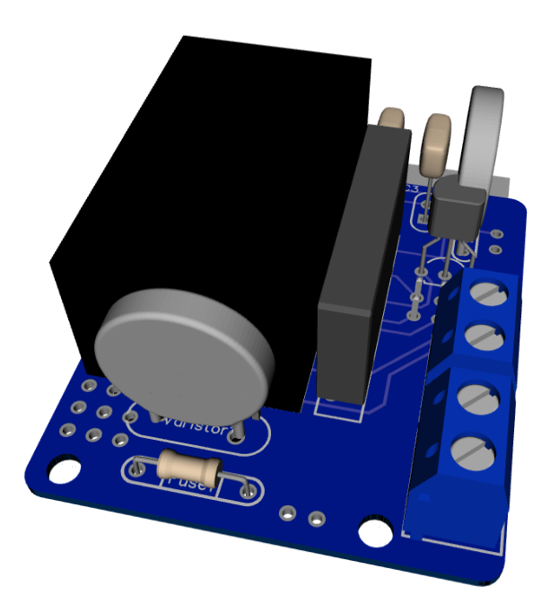
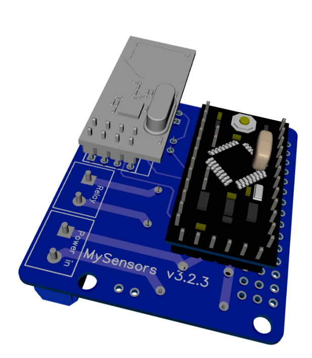
As promised, I've got an update for this project. The board has been tested in the past week, and everything is working as expected. Compared to the previous board I've posted, I have updated the following:
• Solder pads of LE33CZ have been placed a little wider apart to avoid short circuit while soldering.
• Solder pads of the resettable fuse (Fuse2) has been placed closer together to better fit the fuses of the BOM.
• Moved the NRF24L01 connector a bit away from the solid state relay. Should make it easier to solder.
• Moved Fuse2 to another location on the board, away from the 230v circuit.Some 3D pictures (Top and bottom):
Anyone who is interested can order the PCB HERE
Some documentation, and all gerber / DipTrace files (in case you would like to make some modifications) can be found here: MySensors board v3.2.3.zip.