Trying to do a 3 dimmer Led controller with motion
-
This is based on the main page of the builds dimmable LED but I want to use 3 Dimmers for RGB LED strip. All on full brightness equalls white! But the code is giving me some trouble this is what I have so far but only 1 Dimmer and Motion show up in my Vera, the 2 other dimmers are not showing or working any help would be nice. :)
/***
 * This program is free software; you can redistribute it and/or
 * modify it under the terms of the GNU General Public License
 * version 2 as published by the Free Software Foundation.
 *
 * DESCRIPTION
 * This sketch provides a 3 Color Dimmable LED Light using PWM and based Henrik Ekblad
 * <henrik.ekblad@gmail.com> Vera Arduino Sensor project.
 * And Based on Bruce Lacey, inspired by Hek's MySensor's example sketches.
 *
 * The circuit uses a MOSFET for Pulse-Wave-Modulation to dim the attached LED or LED strip.
 * The MOSFET Gate pin is connected to Arduino pin 3,5,6 (LED_PIN), the MOSFET Drain pin is connected
 * to the LED negative terminal and the MOSFET Source pin is connected to ground.
 *
 *
 * REVISION HISTORY
 * Version 1.0 - February 15, 2014 - Bruce Lacey
 * Version 1.1 - August 13, 2014 - Converted to 1.4 (hek)
 * Version 1.2 - Hacked up by Jeff Wooding (DrJeff)
 *
 ***/
#define SN "DimmableColorLED"
#define SV "1.2"
#define NODE_ID AUTO  //change to a number to assign a specific ID

#include <MySensor.h>
#include <SPI.h>

#define RLED_PIN_CHILD 0   //ID of the RED LED child
#define GLED_PIN_CHILD 1   //ID of the GREEN LED child
#define BLED_PIN_CHILD 2   //ID of the BLUE LED child
#define MOTION_CHILD 3    //ID of the MOTION child

#define RLED_PIN 3      // Arduino pin attached to MOSFET Gate pin
#define GLED_PIN 5      // Arduino pin attached to MOSFET Gate pin
#define BLED_PIN 6      // Arduino pin attached to MOSFET Gate pin
#define MOTION_PIN  4  // Arduino pin tied to trigger pin on the motion sensor.

#define FADE_DELAY 10  // Delay in ms for each percentage fade up/down (10ms = 1s full-range dim)

//MySensor gw(0,9);
MySensor gw; //Don't need to define pins unless they are changing from the default

static int currentLevel = 0;  // Current dim level...
MyMessage dimmerMsg(0, V_DIMMER);
MyMessage lightMsg(0, V_LIGHT);

//added 1,2
MyMessage dimmerMsg1(1, V_DIMMER);
MyMessage lightMsg1(1, V_LIGHT);

MyMessage dimmerMsg2(2, V_DIMMER);
MyMessage lightMsg2(2, V_LIGHT);

//motion sensor
MyMessage motionMsg(MOTION_CHILD, V_TRIPPED);
uint8_t lastMotion = 0;


unsigned long previousMillis = 0; // last time update //see http://stackoverflow.com/questions/10773425/performing-a-function-after-x-time for more details on this
unsigned long motionDelay = 10000; // interval at which to keep motion sensor trippped (milliseconds).  Used to prevent too frequent updates to Vera.

boolean metric = true;

/***
 * Dimmable LED initialization method
 */
void setup()
{
  Serial.println( SN );
  gw.begin( incomingMessage );

  // Register the LED Dimmable Light with the gateway
  gw.present( RLED_PIN_CHILD, S_DIMMER );
  gw.present( GLED_PIN_CHILD, S_DIMMER );
  gw.present( BLED_PIN_CHILD, S_DIMMER );
  gw.present( MOTION_CHILD, S_MOTION );

  gw.sendSketchInfo(SN, SV);
  metric = gw.getConfig().isMetric;
  // Pull the gateway's current dim level - restore light level upon sendor node power-up
  gw.request( RLED_PIN_CHILD, V_DIMMER );
  gw.request( GLED_PIN_CHILD, V_DIMMER );
  gw.request( BLED_PIN_CHILD, V_DIMMER );

}

/***
 *  Dimmable LED main processing loop
 */
void loop()
{
  gw.process();


   //motion sensor code
  unsigned long currentMillis = millis();

     if(currentMillis - previousMillis > motionDelay){
      uint8_t motionDetect = digitalRead(MOTION_PIN);

      if(motionDetect != lastMotion){
//        Serial.print("motionDetect Value: ");
//        Serial.println(motionDetect);
        gw.send(motionMsg.set(motionDetect));  // Send tripped value to gw

        if(motionDetect == 1){
          previousMillis = currentMillis;  //"Tripped" delay
        }
        else{
          previousMillis = currentMillis - motionDelay + 1000; //"Not tripped" delay for 1 second to stop rapid "not tripped" and "tripped" updates to Vera
        }

         lastMotion = motionDetect;
      }
}
}
/***
 *  This method provides a graceful fade up/down effect
 */
void fadeToLevel( int toLevel ) {

  int delta = ( toLevel - currentLevel ) < 0 ? -1 : 1;

  while ( currentLevel != toLevel ) {
    currentLevel += delta;
    analogWrite( RLED_PIN, (int)(currentLevel / 100. * 255) );
    delay( FADE_DELAY );
  }
while ( currentLevel != toLevel ) {
    currentLevel += delta;
    analogWrite( GLED_PIN, (int)(currentLevel / 100. * 255) );
    delay( FADE_DELAY );
  }
  while ( currentLevel != toLevel ) {
    currentLevel += delta;
    analogWrite( BLED_PIN, (int)(currentLevel / 100. * 255) );
    delay( FADE_DELAY );
  }
}


void incomingMessage(const MyMessage &message) {
  if (message.type == V_LIGHT || message.type == V_DIMMER) {

    //  Retrieve the power or dim level from the incoming request message
    int requestedLevel = atoi( message.data );

    // Adjust incoming level if this is a V_LIGHT variable update [0 == off, 1 == on]
    requestedLevel *= ( message.type == V_LIGHT ? 100 : 1 );

    // Clip incoming level to valid range of 0 to 100
    requestedLevel = requestedLevel > 100 ? 100 : requestedLevel;
    requestedLevel = requestedLevel < 0   ? 0   : requestedLevel;

    Serial.print( "Changing level to " );
    Serial.print( requestedLevel );
    Serial.print( ", from " );
    Serial.println( currentLevel );

    fadeToLevel( requestedLevel );

    // Inform the gateway of the current DimmableLED's SwitchPower1 and LoadLevelStatus value...
    gw.send(lightMsg.set(currentLevel > 0 ? 1 : 0));
    //added
    gw.send(lightMsg1.set(currentLevel > 0 ? 1 : 0));
    gw.send(lightMsg2.set(currentLevel > 0 ? 1 : 0));

    // hek comment: Is this really nessesary?
    gw.send( dimmerMsg.set(currentLevel) );
    //added
    gw.send( dimmerMsg1.set(currentLevel) );
    gw.send( dimmerMsg2.set(currentLevel) );

    }

}
I would also like to add a Rotary encoder to this but I think I'm tapped out on the PWM pins to make it work. Any Ideas? Another thought would be to use a separate board/pro mini and dim it remotely?
-
By using built-in PWM you are limited to 3 outputs (3, 5 and 6), as pins 9, 10 and 11 are being used to connect to nRF radio).
To read the rotaries you need at least two pins for each ( = "2-bit gray code"). Most rotaries have a 3rd microswitch, and work as a push-button as well, so a extra pin will allow you to have a on-off switch by pushing (instead turning) the rotary .
Below is my sketch with 3 dimmers (using timers). If you implement timers, you can use any pin. (and it also works with AC-Triacs --- Be careful!!!) . If you are dimming AC bulbs, you need to adjust the 'freqStep' variable according to the AC frequency of your region.
int freqStep = 84; // Microseconds of each tic = 1s / 60Hz * 100 stepsI also recommend a 16Mhz Arduino, so you have enough speed to achieve good fade effects in all 3 channels while not missing any radio message.
Dimmer 1 & 2 can be controlled by rotaries connected on (A3,A4) and (A5,A6). I also use A0 and A1 to immediate on/off by pushing each rotary. Dimmer 3 can only be increased/decreased via Incoming message (although it has a local on/off switch on pin A2).
Hope it helps!
/***
 *
 * 3x Bulb/Led dimmer
 *
 ***/

#include <TimerOne.h>
#include <MySensor.h>
#include <SPI.h>
#include <IRLib.h>

#define SN "theDimmer"
#define SV "1.3"

// Version history
// 1.2 4-Apr-15: Include "fade to level" logic
// 1.3 11-Apr-15:  Changed A0-A6 input pins order; code cleanup

// MySensor gateway, dimmer & light messages
MySensor gw;
MyMessage msg1[3];
MyMessage msg2[3];

// Infrared Send module
IRsend irsend;

// Warning message
MyMessage var1( 0 , V_VAR1);
volatile boolean AC_found = false;

// Dim Level
int level[3] ;    // Current dim level on OUTPUT pins (0 to 100)
int level_gw[3];  // Current dim level at Controller
int level_tg[3];  // Current dim level (target)
float gap;

// Output pins (to Triacs / MOSFETs)
int out_pin[3] = { 5, 6, 7 };  // Output PINS

// Input: local rotary encoders (only 2) - 2-bit gray code
int a,b,oldA[2],oldB[2];
int rotary[2][2] = {  { A3 , A4 }  ,  { A5, A6 } };  // INPUT PINS

// Input: local switches
boolean newSw, oldSw[3];
long lastSw[3];
int sw[3] = { A0, A1, A2 };  // INPUT PINS

// Infrared Emiiter Pin
#define IR_PIN 3
unsigned long raw[400];   // raw sequence of IR codes

// Clock ticker (100 tics = 1 AC wave cycle = 1s / 120Hz = 8333 milisecs
volatile int counter = 100;          // Timer tick counter
int freqStep = 84;                   // Microseconds of each tic  =  1s / 60Hz * 100 steps
volatile boolean zero_cross = false; // Zero-cross flag
int zero_cross_pin = 2;             // Input PIN for zero-cross detection
volatile int int_ct = 0 ;

// Idle counter (for gw update);
boolean idle;
int idle_ct;

void setup() {

  // Serial init
  Serial.begin(115200);

  // Start radio Controller
  gw.begin( incomingMessage );
  gw.sendSketchInfo( SN, SV );

  // IR output available?
  pinMode( IR_PIN, INPUT );
  delay(50);
  if ( digitalRead( IR_PIN ) == LOW ) {
    pinMode( IR_PIN , OUTPUT );
    gw.present( 4 , S_IR );
    Serial.println("IR init");
  }

  // Setup IN/OUT pins
  for (int i = 0; i < 3; i++ ) {

    // levels / step
    level[i] = 0;
    level_gw[i]=0;
    level_tg[i]=0;

    // Create return messages
    msg1[i] = MyMessage( i , V_DIMMER ) ;
    msg2[i] = MyMessage( i , V_LIGHT ) ;

    // Rotary Encoders
    if ( i < 2) {
      pinMode( rotary[i][0] , INPUT_PULLUP );
      pinMode( rotary[i][1] , INPUT_PULLUP );
      oldA[i] = digitalRead( rotary[i][0] );
      oldB[i] = digitalRead( rotary[i][1] );
    }

    // Input Switches/PBs
    pinMode( sw[i] , INPUT_PULLUP );
    oldSw[i] = digitalRead( sw[i] );
    lastSw[i] = millis();

    // Triac/MOSFET out
    pinMode( out_pin[i], INPUT );
    delay(50);
    if ( digitalRead( out_pin[i] ) == LOW ) {

      pinMode( out_pin[i] , OUTPUT );
      digitalWrite( out_pin[i], LOW );

      // Register Dimmable Lights with the gateway
      gw.present( i, S_DIMMER );

      // Fetchs previous state from controller
      gw.request( i , V_DIMMER );

      Serial.print("Dimmer init CH ");
      Serial.println( i );

    }

  }

  // Zero-cross detection on Pin 2
  pinMode( zero_cross_pin , INPUT_PULLUP);
  attachInterrupt( 0, zero_cross_detect, RISING );

  // Clock ticker
  Timer1.initialize();
  Timer1.attachInterrupt( dim_check , freqStep );

}

// Zero-cross
void zero_cross_detect() {

  zero_cross = true;
  AC_found = true;
  counter = 100;
  for (int i=0; i<3; i++)  digitalWrite( out_pin[i], LOW ) ;

}

// Timer Ticker - check
void dim_check() {

  int j = 0;

  if ( zero_cross == true ) {

    for (int i=0; i<3; i++)
      if ( counter <= level[i] ) {
        digitalWrite( out_pin[i] , HIGH );
        j++;
      }


    // If all 3 output fires, avoid further checks...
    if ( j == 3) zero_cross = false;
  }

  // Tic-tac...
  counter--;

  // No zero-cross circuit?  As contingency, emulate it based on timer
  // (Should work at least for PWM led running by  MOSFET )
  if ( counter == 0 ) {

    zero_cross = true;
    counter = 100;
    for (int i=0; i<3; i++)  digitalWrite( out_pin[i], LOW ) ;
  }

}

void loop() {

  // Automation controller
  gw.process();

  // Idle flag
  idle = true;

  // gap step calculation
  gap = 0.0;

  // Smooth transition to target level
  for (int i=0; i<3; i++) {
    if ( level[i] != level_tg[i] )  {
       gap = ( ( level_tg[i] - level[i] ) / 25.0 );
       if ( gap > 0.0 && gap < 1.0 ) gap = 1.0 ;
       if ( gap < 0.0 && gap > -1.0 ) gap = -1.0;
             level[i] += gap;
    }
  }

  // Small delay to produce the fade effect
  if ( gap != 0 )   delay(27);  // Aprox. .7s  (=700/25) of ramp up/down

  // Read the Rotary Encoders
  for (int i=0; i<2; i++) {

    // Read current state
    a = digitalRead( rotary[i][0] );
    b = digitalRead( rotary[i][1] );

    // Any change?
    if ( a != oldA[i] || b != oldB[i] ) {

      idle = false;
      idle_ct = 0;

      if ( oldA[i] == LOW && oldB[i] == LOW ) {

        a == HIGH ?  level[i]-=8 : level[i]+=8 ;

        if ( level_tg[i] > 100 )  level_tg[i] = 100;
        if ( level_tg[i] < 0 )    level_tg[i] = 0;

      }

      // Save to use later...
      oldA[i] = a;
      oldB[i] = b;
      delay(3);
    }
  }

  // Read local Push button
  for (int i=0; i<3; i++) {

    // Check SWs
    newSw = digitalRead( sw[i] );

    // Any change?
    if ( newSw != oldSw[i] ) {

      // Not idle anymore...
      idle = false;
      idle_ct =  0;

      // Minimum push to swap state
      if ( millis() - lastSw[i] > 500 ) {

        level_tg[i] > 0 ? level_tg[i] = 0 : level_tg[i] = 100;

      }

      // Save to use later...
      oldSw[i] = newSw;
      lastSw[i] = millis();
      delay(50);

    }

  }

  if (idle) {

    if ( ++idle_ct > 15000 ) {   // (about 1s)

      // Check for not-updated levels on GW-controller
      for (int i=0; i<3; i++) {

        // Update Level in GW-controller
        if ( level_gw[i] != level[i] ) {

          // update GW-controller
          // Send new state and request ack back
          gw.send( msg1[i].set( level[i] ) );
          gw.send( msg2[i].set( level[i] > 0 ? true : false ) );
          level_gw[i] = level[i];

        }

        // Warning message for no zero-cross detected
        if ( !AC_found ) {
          gw.send( var1.set( "No AC?") ) ;
          AC_found = true ;
        }
      }

      // Reset idle counter
      idle_ct = 0;
    }

  }

}


void incomingMessage(const MyMessage &message)
{

  // ACK
  if (message.isAck()) {
    // Nothing to do, just ACK from Gateway
    //irsend.send(NEC, 0x1EE17887, 32); // Vol up yamaha ysp-900
   // irsend.send(NEC, 0x1EE1F807, 32); // Vol down yamaha ysp-900
  }
  else {

    // IR Output
    if ( message.type == V_IR_SEND )
    {

     // TO DO

    }

    // Light/Dimmer messages
    if ( message.type == V_LIGHT || message.type == V_DIMMER )
    {

      //  Retrieve the power or dim level from the incoming request message
      int requestedLevel = atoi( message.data );

      // Channel
      int i = message.sensor;

      // Adjust incoming level if this is a V_LIGHT variable update [0 == off, 1 == on]
      requestedLevel *= ( message.type == V_LIGHT ? 100 : 1 );

      // Clip incoming level to valid range of 0 to 100
      requestedLevel = requestedLevel > 100 ? 100 : requestedLevel;
      requestedLevel = requestedLevel < 0   ? 0   : requestedLevel;

      // Set new level
      level_tg[i] = requestedLevel;
      level_gw[i] = requestedLevel;

    }
  }
}
Home Assistant / Vera Plus UI7
ESP8266 GW + mySensors 2.3.2
Alexa / Google Home -
By using built-in PWM you are limited to 3 outputs (3, 5 and 6), as pins 9, 10 and 11 are being used to connect to nRF radio).
To read the rotaries you need at least two pins for each ( = "2-bit gray code"). Most rotaries have a 3rd microswitch, and work as a push-button as well, so a extra pin will allow you to have a on-off switch by pushing (instead turning) the rotary .
Below is my sketch with 3 dimmers (using timers). If you implement timers, you can use any pin. (and it also works with AC-Triacs --- Be careful!!!) . If you are dimming AC bulbs, you need to adjust the 'freqStep' variable according to the AC frequency of your region.
int freqStep = 84; // Microseconds of each tic = 1s / 60Hz * 100 stepsI also recommend a 16Mhz Arduino, so you have enough speed to achieve good fade effects in all 3 channels while not missing any radio message.
Dimmer 1 & 2 can be controlled by rotaries connected on (A3,A4) and (A5,A6). I also use A0 and A1 to immediate on/off by pushing each rotary. Dimmer 3 can only be increased/decreased via Incoming message (although it has a local on/off switch on pin A2).
Hope it helps!
/*** * * 3x Bulb/Led dimmer * ***/ #include <TimerOne.h> #include <MySensor.h> #include <SPI.h> #include <IRLib.h> #define SN "theDimmer" #define SV "1.3" // Version history // 1.2 4-Apr-15: Include "fade to level" logic // 1.3 11-Apr-15: Changed A0-A6 input pins order; code cleanup // MySensor gateway, dimmer & light messages MySensor gw; MyMessage msg1[3]; MyMessage msg2[3]; // Infrared Send module IRsend irsend; // Warning message MyMessage var1( 0 , V_VAR1); volatile boolean AC_found = false; // Dim Level int level[3] ; // Current dim level on OUTPUT pins (0 to 100) int level_gw[3]; // Current dim level at Controller int level_tg[3]; // Current dim level (target) float gap; // Output pins (to Triacs / MOSFETs) int out_pin[3] = { 5, 6, 7 }; // Output PINS // Input: local rotary encoders (only 2) - 2-bit gray code int a,b,oldA[2],oldB[2]; int rotary[2][2] = { { A3 , A4 } , { A5, A6 } }; // INPUT PINS // Input: local switches boolean newSw, oldSw[3]; long lastSw[3]; int sw[3] = { A0, A1, A2 }; // INPUT PINS // Infrared Emiiter Pin #define IR_PIN 3 unsigned long raw[400]; // raw sequence of IR codes // Clock ticker (100 tics = 1 AC wave cycle = 1s / 120Hz = 8333 milisecs volatile int counter = 100; // Timer tick counter int freqStep = 84; // Microseconds of each tic = 1s / 60Hz * 100 steps volatile boolean zero_cross = false; // Zero-cross flag int zero_cross_pin = 2; // Input PIN for zero-cross detection volatile int int_ct = 0 ; // Idle counter (for gw update); boolean idle; int idle_ct; void setup() { // Serial init Serial.begin(115200); // Start radio Controller gw.begin( incomingMessage ); gw.sendSketchInfo( SN, SV ); // IR output available? pinMode( IR_PIN, INPUT ); delay(50); if ( digitalRead( IR_PIN ) == LOW ) { pinMode( IR_PIN , OUTPUT ); gw.present( 4 , S_IR ); Serial.println("IR init"); } // Setup IN/OUT pins for (int i = 0; i < 3; i++ ) { // levels / step level[i] = 0; level_gw[i]=0; level_tg[i]=0; // Create return messages msg1[i] = MyMessage( i , V_DIMMER ) ; msg2[i] = MyMessage( i , V_LIGHT ) ; // Rotary Encoders if ( i < 2) { pinMode( rotary[i][0] , INPUT_PULLUP ); pinMode( rotary[i][1] , INPUT_PULLUP ); oldA[i] = digitalRead( rotary[i][0] ); oldB[i] = digitalRead( rotary[i][1] ); } // Input Switches/PBs pinMode( sw[i] , INPUT_PULLUP ); oldSw[i] = digitalRead( sw[i] ); lastSw[i] = millis(); // Triac/MOSFET out pinMode( out_pin[i], INPUT ); delay(50); if ( digitalRead( out_pin[i] ) == LOW ) { pinMode( out_pin[i] , OUTPUT ); digitalWrite( out_pin[i], LOW ); // Register Dimmable Lights with the gateway gw.present( i, S_DIMMER ); // Fetchs previous state from controller gw.request( i , V_DIMMER ); Serial.print("Dimmer init CH "); Serial.println( i ); } } // Zero-cross detection on Pin 2 pinMode( zero_cross_pin , INPUT_PULLUP); attachInterrupt( 0, zero_cross_detect, RISING ); // Clock ticker Timer1.initialize(); Timer1.attachInterrupt( dim_check , freqStep ); } // Zero-cross void zero_cross_detect() { zero_cross = true; AC_found = true; counter = 100; for (int i=0; i<3; i++) digitalWrite( out_pin[i], LOW ) ; } // Timer Ticker - check void dim_check() { int j = 0; if ( zero_cross == true ) { for (int i=0; i<3; i++) if ( counter <= level[i] ) { digitalWrite( out_pin[i] , HIGH ); j++; } // If all 3 output fires, avoid further checks... if ( j == 3) zero_cross = false; } // Tic-tac... counter--; // No zero-cross circuit? As contingency, emulate it based on timer // (Should work at least for PWM led running by MOSFET ) if ( counter == 0 ) { zero_cross = true; counter = 100; for (int i=0; i<3; i++) digitalWrite( out_pin[i], LOW ) ; } } void loop() { // Automation controller gw.process(); // Idle flag idle = true; // gap step calculation gap = 0.0; // Smooth transition to target level for (int i=0; i<3; i++) { if ( level[i] != level_tg[i] ) { gap = ( ( level_tg[i] - level[i] ) / 25.0 ); if ( gap > 0.0 && gap < 1.0 ) gap = 1.0 ; if ( gap < 0.0 && gap > -1.0 ) gap = -1.0; level[i] += gap; } } // Small delay to produce the fade effect if ( gap != 0 ) delay(27); // Aprox. .7s (=700/25) of ramp up/down // Read the Rotary Encoders for (int i=0; i<2; i++) { // Read current state a = digitalRead( rotary[i][0] ); b = digitalRead( rotary[i][1] ); // Any change? if ( a != oldA[i] || b != oldB[i] ) { idle = false; idle_ct = 0; if ( oldA[i] == LOW && oldB[i] == LOW ) { a == HIGH ? level[i]-=8 : level[i]+=8 ; if ( level_tg[i] > 100 ) level_tg[i] = 100; if ( level_tg[i] < 0 ) level_tg[i] = 0; } // Save to use later... oldA[i] = a; oldB[i] = b; delay(3); } } // Read local Push button for (int i=0; i<3; i++) { // Check SWs newSw = digitalRead( sw[i] ); // Any change? if ( newSw != oldSw[i] ) { // Not idle anymore... idle = false; idle_ct = 0; // Minimum push to swap state if ( millis() - lastSw[i] > 500 ) { level_tg[i] > 0 ? level_tg[i] = 0 : level_tg[i] = 100; } // Save to use later... oldSw[i] = newSw; lastSw[i] = millis(); delay(50); } } if (idle) { if ( ++idle_ct > 15000 ) { // (about 1s) // Check for not-updated levels on GW-controller for (int i=0; i<3; i++) { // Update Level in GW-controller if ( level_gw[i] != level[i] ) { // update GW-controller // Send new state and request ack back gw.send( msg1[i].set( level[i] ) ); gw.send( msg2[i].set( level[i] > 0 ? true : false ) ); level_gw[i] = level[i]; } // Warning message for no zero-cross detected if ( !AC_found ) { gw.send( var1.set( "No AC?") ) ; AC_found = true ; } } // Reset idle counter idle_ct = 0; } } } void incomingMessage(const MyMessage &message) { // ACK if (message.isAck()) { // Nothing to do, just ACK from Gateway //irsend.send(NEC, 0x1EE17887, 32); // Vol up yamaha ysp-900 // irsend.send(NEC, 0x1EE1F807, 32); // Vol down yamaha ysp-900 } else { // IR Output if ( message.type == V_IR_SEND ) { // TO DO } // Light/Dimmer messages if ( message.type == V_LIGHT || message.type == V_DIMMER ) { // Retrieve the power or dim level from the incoming request message int requestedLevel = atoi( message.data ); // Channel int i = message.sensor; // Adjust incoming level if this is a V_LIGHT variable update [0 == off, 1 == on] requestedLevel *= ( message.type == V_LIGHT ? 100 : 1 ); // Clip incoming level to valid range of 0 to 100 requestedLevel = requestedLevel > 100 ? 100 : requestedLevel; requestedLevel = requestedLevel < 0 ? 0 : requestedLevel; // Set new level level_tg[i] = requestedLevel; level_gw[i] = requestedLevel; } } }@rvendrame said:
3 dimmers (using timers). If you implement timers, you can use any pin. (and it also works with AC-Triacs --- Be careful!!!) .
What is the caution for? Just that I'm working with 120V or is there something I'm Missing here? Will it go up in flames based on the timer circuit?
I love the way you did this I was trying to do the A/C dimmer (asked in another thread), The hardware was pretty simple but the code was sooooo hard to figure out I will give this a shot! I will also use this with my LED dimmer you have fixed two of my problems with, wait three you got IR in here also! Yippe!
You Rock! @rvendrame
-
Thanks. Working with Triacs is a way more dangerous than relays, in terms of isolation from AC mains. The terminals are very close, and in many triacs models the heat terminal (where you attach the heat sink) is electrically connected to the input/output terminals.
You must know what you are doing, under the risk of serious injury to you or someone else.
In many countries only a certified electrician can work on AC mains. And only certified devices can be installed in wall boxes, to avoid risk of fire.
Be careful! ;-)
Home Assistant / Vera Plus UI7
ESP8266 GW + mySensors 2.3.2
Alexa / Google Home -
Thanks. Working with Triacs is a way more dangerous than relays, in terms of isolation from AC mains. The terminals are very close, and in many triacs models the heat terminal (where you attach the heat sink) is electrically connected to the input/output terminals.
You must know what you are doing, under the risk of serious injury to you or someone else.
In many countries only a certified electrician can work on AC mains. And only certified devices can be installed in wall boxes, to avoid risk of fire.
Be careful! ;-)
@rvendrame Do share your circuit I would love to compare. I found the inmojo circuit to work well. My only missing piece is I want to power the circuit with s tranformerless power supply.
-
@DrJeff , I plan to document everything and post at the forum later, probably once I incorporate the IR emitter in my project. ;-)
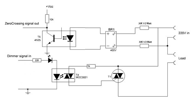
I forgot to mention the zero-cross detection (on pin2), you will need it if you dimm regular AC bulbs (doesn't matter how many dimmer channels you have, only one zero-cross is enough).
The picture above show the zero-cross on top and one dimmer channel on bottom.
Hello! It looks like you're interested in this conversation, but you don't have an account yet.
Getting fed up of having to scroll through the same posts each visit? When you register for an account, you'll always come back to exactly where you were before, and choose to be notified of new replies (either via email, or push notification). You'll also be able to save bookmarks and upvote posts to show your appreciation to other community members.
With your input, this post could be even better 💗
Register Login