Safe In-Wall AC to DC Transformers??
-
Found what seems to be a interesting article: https://www.ieee.li/pdf/essay/safety_considerations_in_power_supply_design.pdf (Texas instrument).
Not read through it or know if the source is reliable but Texas instrument seems like a good author/source. No references inside so I guess its "how they see it".@sundberg84 Ok, I understand. I will defer to the experts here and update the first post when a consensus is reached. I do have one more thing I'd like clarified though. It still seems to me like a 200/300mA slow fuse would be better as it would survive small over-current spikes but it wouldn't allow sustained draws over the HLK's rating of 200mA. With a 600mA fast blow fuse the HLK could draw 500mA as long as it wanted without blowing. Maybe this doesn't matter though?
On a side note, when I tested one of my slow blow fuses it still blew pretty fast with a moderate load above it's specs. I tested with a 33 watt floresent bulb and it blew in less than a second (not sure of the exact time/wattage as it was really just a test to see if it was a fuse and not something else).
-
Transformers typically have an in-rush current as well, so a fast-blow fuse could pop because of this if it's not sized for that.
Cheers
Al -
Interesting @Sparkman!
https://en.wikipedia.org/wiki/Inrush_current "When a transformer is first energized, a transient current up to 10 to 15 times larger than the rated transformer current can flow for several cycles." -
This in-rush 'effect' can be seen on any induction load.
-
I´m no expert but I thought and researched some. Could be wrong, please correct me then.
I think you're confusing AC inductive load inrush current with what we're interested in, which is the inrush to our switched power supplies. In our case the inrush current is to the primary side rectifier filter capacitor, not to the transformer. The transformer inside SMPS is for high frequency and would probably give a small inrush even if it was subjected to normal AC. Now it's DC and behind the switch controller and FET. And the controllers I've seen usually have some start-up time.
General about fast/slow types of small fuses (from here):
The fuses must not open in less than one hour at 125% of rated current and open within two minutes at 200% of rated current. The 1000% overload is used to determine the fuse characteristic. The opening time for each rating is listed below.
Type FF: Less than 0.001 sec.
Type F: From 0.001 - 0.01 sec.
Type T: From 0.01 - 0.1 sec.
Type TT: From 0.1 - 1.00 sec.
These characteristics correlate to the terminology used in IEC 60127-1.
So in theory a type FF fuse could open "instantly" for 10*In (rated current) ? (in reality you check its specs of course). But let's see how a more normal type F fuse would work given the setup from a "normal" SMPS. I use this, but from what I've seen, primary side looks very similar to the HLK-PM01.
Rectifier filter cap value of my SMPS: 4.7uF
A normal 5x20mm fuse resistance value: 5 ohm (usually more resistances than just the fuse, but let's be conservative)
Max voltage peak-peak 700V ( ~250Vrms )
Regular capacitor calculation:
I(t0) = U/R = 140 A
T = RC = 54.7u = 23,5 us
I(t) = U/Re^-(t/T) = 140*e^-(t/0.0000235)How much inrush current do we have at for e.g. the fastest F-type fuse characteristic:
I(tmin=0.001) = 140e^-(0.001/0.0000235) = 140e^-(1/0.0235) = 3.3*10^-19 (i.e. zero current)How much time until I=0.1A (which would correspond to fuse value 0.01A):
I=U/R*e^-(.) <=> e^-(.)=IR/U <=> (.)=-ln(IR/U) <=> t = -ln(IR/U)0.0000235
t = -ln(0.15/700)*0.0000235 = 0.00017 = 170usSo even a 0.01A type F fuse should be far from blowing in a worst case and with conservative assumptions. For extra fast fuses, type FF, the characteristic must be checked.
Edit: This is only regarding the inrush, of course the load must be added to this eventually.
-
@m26872 So, to sum up - there is no need to use a slow fuse, since the in rush current isnt "long" enough to blow a fast fuse. So considering safety (and if you have the same mA value for both fuses) its better and should work to use a fast rather than slow ??
-
I´m no expert but I thought and researched some. Could be wrong, please correct me then.
I think you're confusing AC inductive load inrush current with what we're interested in, which is the inrush to our switched power supplies. In our case the inrush current is to the primary side rectifier filter capacitor, not to the transformer. The transformer inside SMPS is for high frequency and would probably give a small inrush even if it was subjected to normal AC. Now it's DC and behind the switch controller and FET. And the controllers I've seen usually have some start-up time.
General about fast/slow types of small fuses (from here):
The fuses must not open in less than one hour at 125% of rated current and open within two minutes at 200% of rated current. The 1000% overload is used to determine the fuse characteristic. The opening time for each rating is listed below.
Type FF: Less than 0.001 sec.
Type F: From 0.001 - 0.01 sec.
Type T: From 0.01 - 0.1 sec.
Type TT: From 0.1 - 1.00 sec.
These characteristics correlate to the terminology used in IEC 60127-1.
So in theory a type FF fuse could open "instantly" for 10*In (rated current) ? (in reality you check its specs of course). But let's see how a more normal type F fuse would work given the setup from a "normal" SMPS. I use this, but from what I've seen, primary side looks very similar to the HLK-PM01.
Rectifier filter cap value of my SMPS: 4.7uF
A normal 5x20mm fuse resistance value: 5 ohm (usually more resistances than just the fuse, but let's be conservative)
Max voltage peak-peak 700V ( ~250Vrms )
Regular capacitor calculation:
I(t0) = U/R = 140 A
T = RC = 54.7u = 23,5 us
I(t) = U/Re^-(t/T) = 140*e^-(t/0.0000235)How much inrush current do we have at for e.g. the fastest F-type fuse characteristic:
I(tmin=0.001) = 140e^-(0.001/0.0000235) = 140e^-(1/0.0235) = 3.3*10^-19 (i.e. zero current)How much time until I=0.1A (which would correspond to fuse value 0.01A):
I=U/R*e^-(.) <=> e^-(.)=IR/U <=> (.)=-ln(IR/U) <=> t = -ln(IR/U)0.0000235
t = -ln(0.15/700)*0.0000235 = 0.00017 = 170usSo even a 0.01A type F fuse should be far from blowing in a worst case and with conservative assumptions. For extra fast fuses, type FF, the characteristic must be checked.
Edit: This is only regarding the inrush, of course the load must be added to this eventually.
@m26872 I'm no expert either. :smiley: We may be saying the same thing however... I don't think it matters (AC or DC), if there is a transformer in the circuit, there is going to be a current peak on startup. If you have a filter cap before your transformer, you will see 2 peaks. The first one will be caused by the capacitor charging up, and the second from the inductive load caused by the transformer powering up. I'm thinking the 2nd peak should be much less due to the filter cap.
Of course I could be all wrong. :persevere:
-
Here is an interesting article http://www.vptpower.com/wp-content/uploads/downloads/2012/01/info_inrushCurrent.pdf on the subject. Looks like there is a LOT more to it (not that I thought there wasn't) than my over simplified post above.
-
I´m no expert but I thought and researched some. Could be wrong, please correct me then.
I think you're confusing AC inductive load inrush current with what we're interested in, which is the inrush to our switched power supplies. In our case the inrush current is to the primary side rectifier filter capacitor, not to the transformer. The transformer inside SMPS is for high frequency and would probably give a small inrush even if it was subjected to normal AC. Now it's DC and behind the switch controller and FET. And the controllers I've seen usually have some start-up time.
General about fast/slow types of small fuses (from here):
The fuses must not open in less than one hour at 125% of rated current and open within two minutes at 200% of rated current. The 1000% overload is used to determine the fuse characteristic. The opening time for each rating is listed below.
Type FF: Less than 0.001 sec.
Type F: From 0.001 - 0.01 sec.
Type T: From 0.01 - 0.1 sec.
Type TT: From 0.1 - 1.00 sec.
These characteristics correlate to the terminology used in IEC 60127-1.
So in theory a type FF fuse could open "instantly" for 10*In (rated current) ? (in reality you check its specs of course). But let's see how a more normal type F fuse would work given the setup from a "normal" SMPS. I use this, but from what I've seen, primary side looks very similar to the HLK-PM01.
Rectifier filter cap value of my SMPS: 4.7uF
A normal 5x20mm fuse resistance value: 5 ohm (usually more resistances than just the fuse, but let's be conservative)
Max voltage peak-peak 700V ( ~250Vrms )
Regular capacitor calculation:
I(t0) = U/R = 140 A
T = RC = 54.7u = 23,5 us
I(t) = U/Re^-(t/T) = 140*e^-(t/0.0000235)How much inrush current do we have at for e.g. the fastest F-type fuse characteristic:
I(tmin=0.001) = 140e^-(0.001/0.0000235) = 140e^-(1/0.0235) = 3.3*10^-19 (i.e. zero current)How much time until I=0.1A (which would correspond to fuse value 0.01A):
I=U/R*e^-(.) <=> e^-(.)=IR/U <=> (.)=-ln(IR/U) <=> t = -ln(IR/U)0.0000235
t = -ln(0.15/700)*0.0000235 = 0.00017 = 170usSo even a 0.01A type F fuse should be far from blowing in a worst case and with conservative assumptions. For extra fast fuses, type FF, the characteristic must be checked.
Edit: This is only regarding the inrush, of course the load must be added to this eventually.
@m26872 Thanks! So, am I understanding this correctly that we would want a 200mA or 300mA fast blow fuse? Since I know some of us have already purchased the 300mA slow blow fuses do you think it is safe to use them? If I'm understanding correctly they should still blow relatively quickly if they are subjected to high current right?
-
@sundberg84 Yes, a fast fuse should give a higher level of protection without issues.
@RJ_Make That second "inrush" is what I called the load. It's completely governed by the controller and should not stress the fuse more than running overloads. If there's a peak it´s because of capactive load on the output and has nothing to do with the transformer.
Thx for the link. It confirmes that these turn-on-times are a few milliseconds just like the HLK-review said (around 3ms). No chance to superimpose the first peak.@petewill Regarding fast fuse, yes. But the value I don't know. The HLK review shows overload capabilties, but I don't know about the input currents at that point. Honestly I think it's very unlikely that you'll be saved by using a fast fuse instead of a slow. It's more a matter of e.g. better varistor (overvoltage) protection and the personal feeling of maximum safety etc.
-
So there is another safety issue we should discuss for the HLK.
Creepage (separation between two solder eyes measured along the surface) and clearance (shortest distance between as measured through the air) on the AC input.According to datasheet there is 5mm center-center, but real distance with solder and pads its more like 3, maybe 3.5mm.
I found this and this which was a great summary of some IEC standards states that if your are going to use 240v and put the HLK into a environment with pollution degree III higher you need more creppage than 3.2mm. What am i saying? If i understand this right its not safe to use the HLK in any environment where moisture condensation may occur (outside, bathroom). My guess when i try to read the contamination groups is that if you put the HLK inside a sealed case you get the contamination level down to 2 and then we are safe above needed 2,5mm.
To be on the safe side I have in my latest pcb added holes between AC input to increase creepage:

Am i right? Dont know - its hard to read all these articles and Im new to this so please bring anything to the table... corrections, questions or thoughts.
Controller: Proxmox VM - Home Assistant
MySensors GW: Arduino Uno - W5100 Ethernet, Gw Shield Nrf24l01+ 2,4Ghz
MySensors GW: Arduino Uno - Gw Shield RFM69, 433mhz
RFLink GW - Arduino Mega + RFLink Shield, 433mhz -
So there is another safety issue we should discuss for the HLK.
Creepage (separation between two solder eyes measured along the surface) and clearance (shortest distance between as measured through the air) on the AC input.According to datasheet there is 5mm center-center, but real distance with solder and pads its more like 3, maybe 3.5mm.
I found this and this which was a great summary of some IEC standards states that if your are going to use 240v and put the HLK into a environment with pollution degree III higher you need more creppage than 3.2mm. What am i saying? If i understand this right its not safe to use the HLK in any environment where moisture condensation may occur (outside, bathroom). My guess when i try to read the contamination groups is that if you put the HLK inside a sealed case you get the contamination level down to 2 and then we are safe above needed 2,5mm.
To be on the safe side I have in my latest pcb added holes between AC input to increase creepage:
Am i right? Dont know - its hard to read all these articles and Im new to this so please bring anything to the table... corrections, questions or thoughts.
@sundberg84 I think that looks like an excellent idea. I was looking at the tear down of the HLK in the test that was run and it doesn't look like there was any reason for them to do this - at least as far as I could see, there was plenty of room to put those connectors at the corners like the DC side.
-
@sundberg84 How about a watertight enclosure?
In the UK it is IP67 (this is what it means -> http://aceeca.com/handhelds/ip67) -
@TD22057 Yes, you can see in the teardown they have thought about the creepage in the optical feedback unit (cut a hole in PCB) between primary and secondary. I dont know why they so close, but 5mm is enough - maybe they forgot about solder/pads would take some space?
@alexsh1 If i understand Contamination levels right the difference between III and II is that in III occurs conductive contamination so if you seal it up this should get it down to II.
Then there is a difference between materials - and if compare material I and III its a big difference in creepage - does anyone knows what this means? What material is a normal PCB?
Controller: Proxmox VM - Home Assistant
MySensors GW: Arduino Uno - W5100 Ethernet, Gw Shield Nrf24l01+ 2,4Ghz
MySensors GW: Arduino Uno - Gw Shield RFM69, 433mhz
RFLink GW - Arduino Mega + RFLink Shield, 433mhz -
@TD22057 Yes, you can see in the teardown they have thought about the creepage in the optical feedback unit (cut a hole in PCB) between primary and secondary. I dont know why they so close, but 5mm is enough - maybe they forgot about solder/pads would take some space?
@alexsh1 If i understand Contamination levels right the difference between III and II is that in III occurs conductive contamination so if you seal it up this should get it down to II.
Then there is a difference between materials - and if compare material I and III its a big difference in creepage - does anyone knows what this means? What material is a normal PCB?
Maybe they put the pins closer on the AC side than on the DC, to make sure people would not put the unit the wrong way, which could be dangerous? But as you say, they should have done a better job, though.
-
@martinhjelmare - thats a great thought - must be so, but if you think safety they should do the other way around, ac side wide apart and dc closer.
Controller: Proxmox VM - Home Assistant
MySensors GW: Arduino Uno - W5100 Ethernet, Gw Shield Nrf24l01+ 2,4Ghz
MySensors GW: Arduino Uno - Gw Shield RFM69, 433mhz
RFLink GW - Arduino Mega + RFLink Shield, 433mhz -
@martinhjelmare - thats a great thought - must be so, but if you think safety they should do the other way around, ac side wide apart and dc closer.
Yeah, :smile: , they really screwed that up. Unfortunate, when the rest of the design, seems so good.
-
Some more info about Material Groups and CTI reagarding creepage. When i read PCI datasheets with FR-4 material from different pcb manufactures it looks like we are in the III group (worst offcourse).
PCB in better groups (and better CTI) can be found offcourse - just add money.
Also found a clearance and creepage calculator: http://www.creepage.com/ -
This one is not "safe", but it is an In-Wall AC to DC converter. Transformerless. With a 3A Solid state relay:
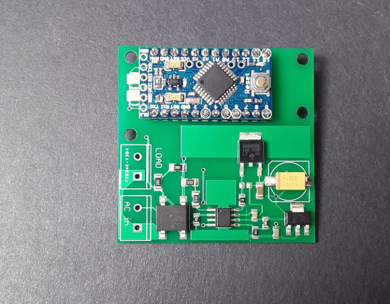
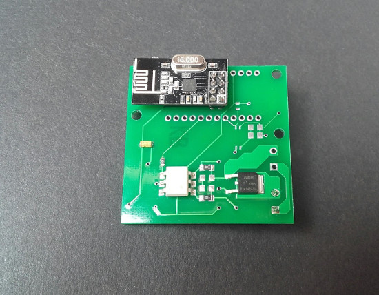
The converter output is 3.3V at 100mA and the solid state relay is a Triac.
-
This solution, if well build locks a lot safer than a standard phone charger. The overheat protection is something that I like a lot. Is ther any pcb that only haves this solution? I found one in the OpenHardware but it integrates the node, I would like some stand alone solution! I think that I will give KiCad a go and try to develop one!