Skip to content
  • MySensors
  • OpenHardware.io
  • Categories
  • Recent
  • Tags
  • Popular
Skins
  • Light
  • Brite
  • Cerulean
  • Cosmo
  • Flatly
  • Journal
  • Litera
  • Lumen
  • Lux
  • Materia
  • Minty
  • Morph
  • Pulse
  • Sandstone
  • Simplex
  • Sketchy
  • Spacelab
  • United
  • Yeti
  • Zephyr
  • Dark
  • Cyborg
  • Darkly
  • Quartz
  • Slate
  • Solar
  • Superhero
  • Vapor

  • Default (No Skin)
  • No Skin
Collapse
Brand Logo
  1. Home
  2. Hardware
  3. Which are the *best* NRF24L01+ modules?

Which are the *best* NRF24L01+ modules?

Scheduled Pinned Locked Moved Hardware
310 Posts 42 Posters 259.2k Views 37 Watching
  • Oldest to Newest
  • Newest to Oldest
  • Most Votes
Reply
  • Reply as topic
Log in to reply
This topic has been deleted. Only users with topic management privileges can see it.
  • NeverDieN NeverDie

    @Zeph said:

    I think TMRH20 has the best RF24 fork, and I've contributed slightly to it in its early days.

    Excellent! In that case, do you happen to know off the top of your head: what's the simplest method or function call in TMRH20 for putting the NRF24L01+ to sleep? If I don't have to research that, I can jump ahead to taking a measurement of it sleeping, as per the above.

    Z Offline
    Z Offline
    Zeph
    Hero Member
    wrote on last edited by Zeph
    #107

    @NeverDie
    http://tmrh20.github.io/RF24/classRF24.html#aa0a51923a09ba4f3478aba9be0f8a6a1

    You are going to need your Davy Jones uCurrent to measure sleeping current!

    1 Reply Last reply
    1
    • NeverDieN Offline
      NeverDieN Offline
      NeverDie
      Hero Member
      wrote on last edited by NeverDie
      #108

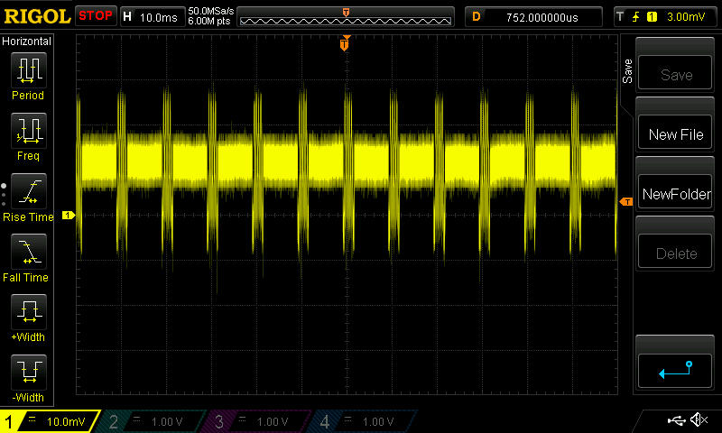
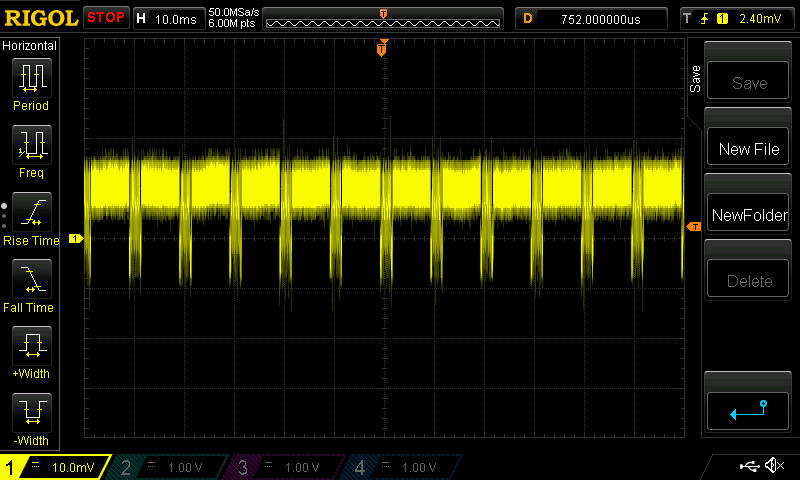
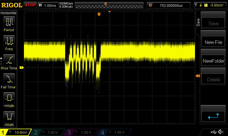
      So, here are the current measurements on the blob module. I used a 1 ohm sense resister, so 1mv=1ma.

      I wrote a short script to transmit a packet once every 10 milliseconds:
      oscope1.jpg

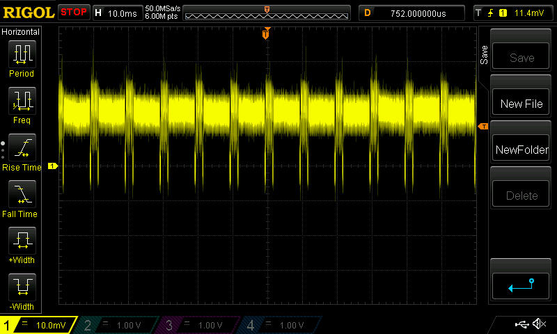
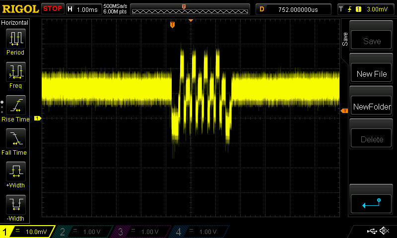
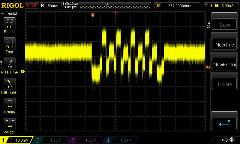
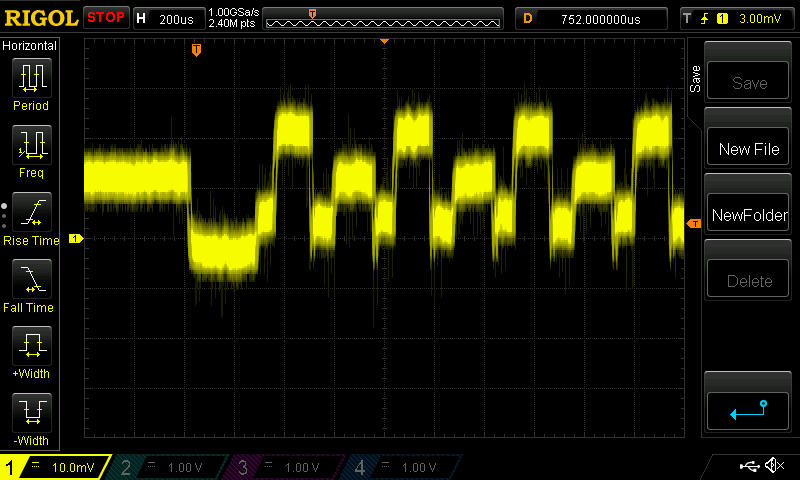
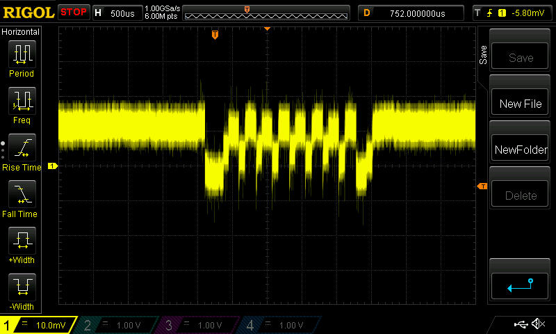
      Now I'll zoom in progressively so you can see for yourself what the current is:
      oscope2.jpg

      oscope3.jpg

      oscope4.jpg

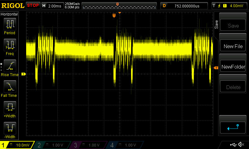
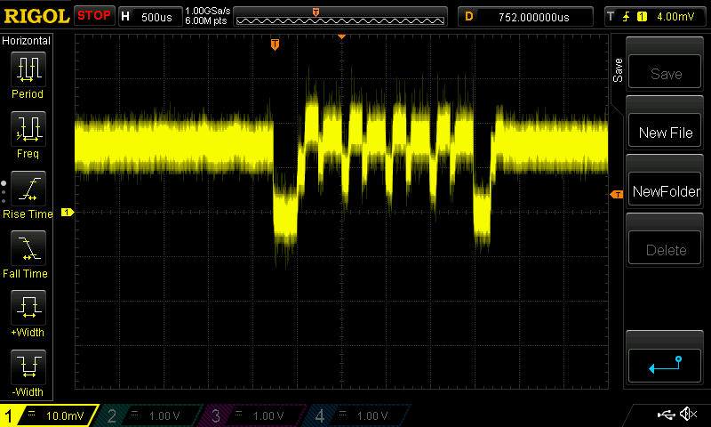
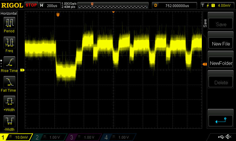
      Doing this measurement is the first time I've ever used an oscilliscope (a Rigole 1054Z). Because the lines are kinda thick (noise, I guess), what would you say the current draw is during a transmission?

      In this case, there is no echo receiver, and so whatever gets sent isn't received by anything.

      1 Reply Last reply
      0
      • NeverDieN Offline
        NeverDieN Offline
        NeverDie
        Hero Member
        wrote on last edited by
        #109

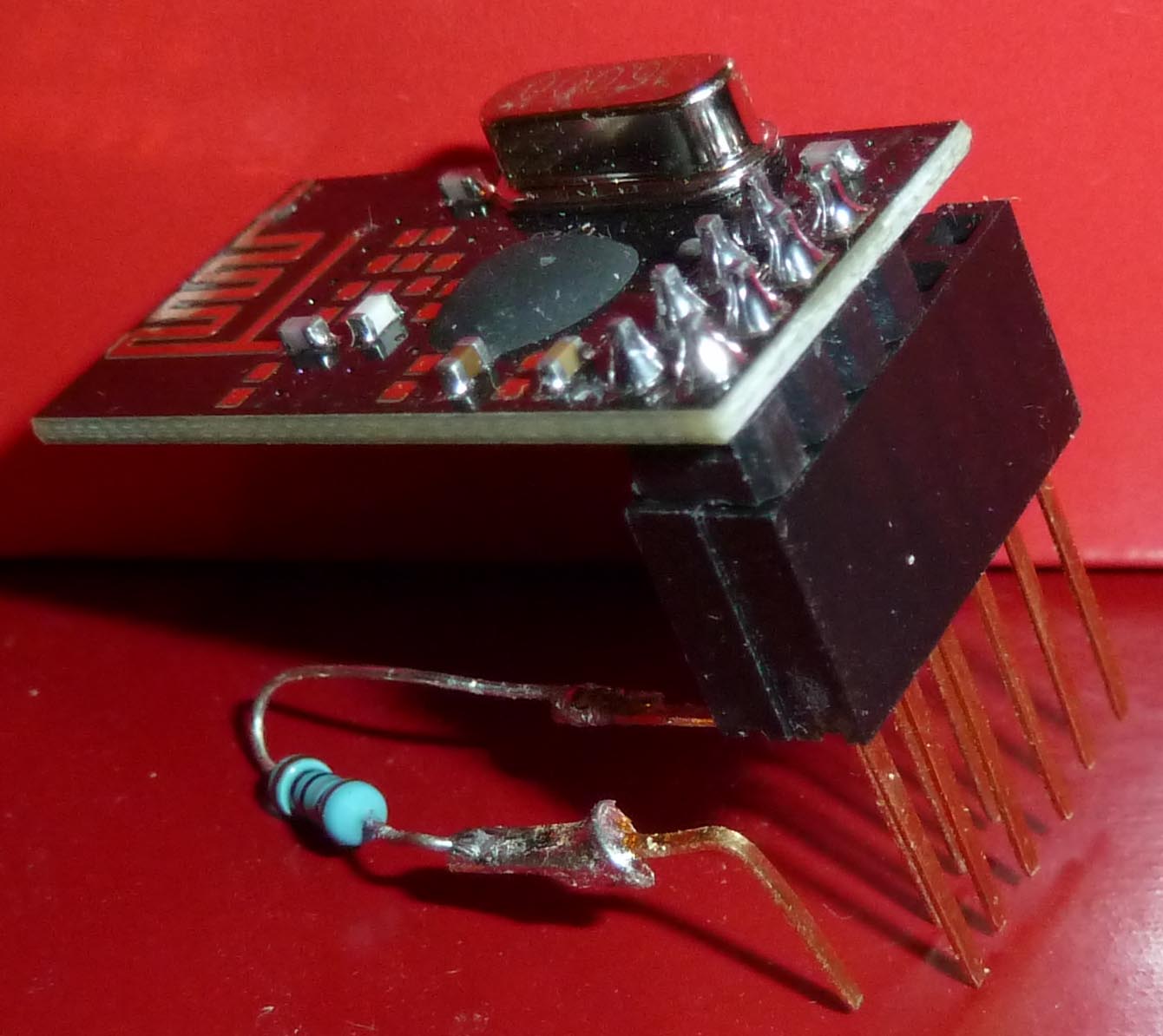
        Here is the simple test jig that I made, using a 1 ohm resistor:
        jig.jpg

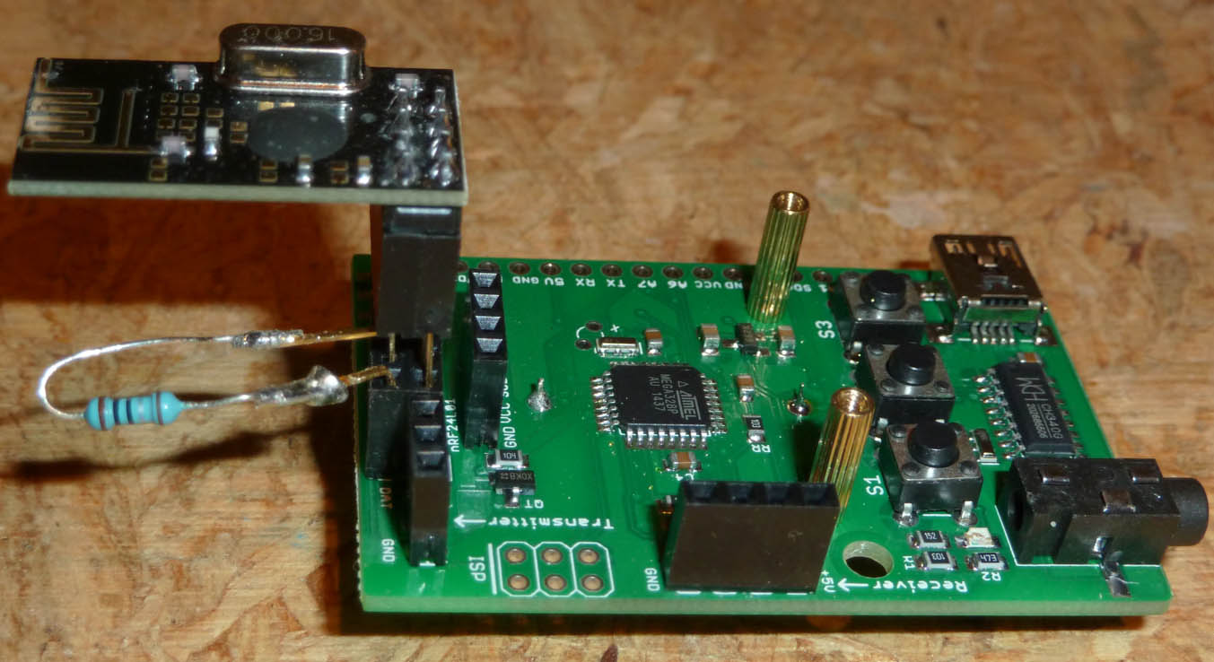
        Here it is mounted on the RFToy:
        mounted.jpg

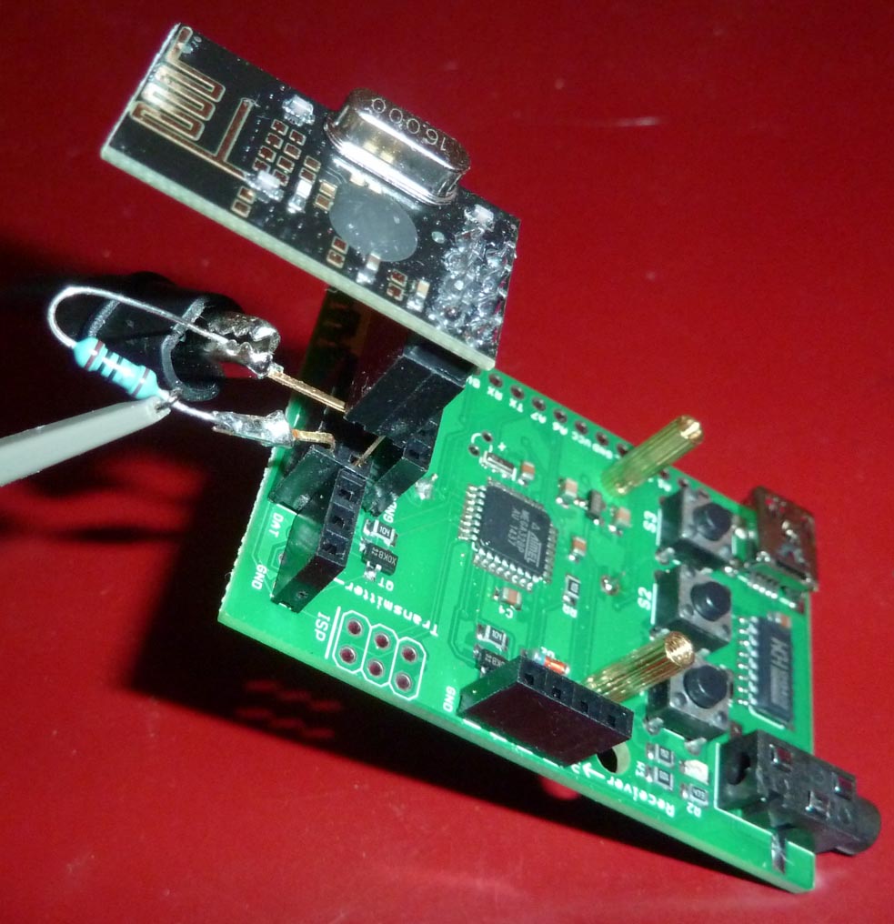
        Here is how I hooked up the oscilloscope probe:
        hookup.jpg

        1 Reply Last reply
        0
        • NeverDieN Offline
          NeverDieN Offline
          NeverDie
          Hero Member
          wrote on last edited by NeverDie
          #110

          For comparison, here are the measurements taken on an ITEAD module:

          itead1.jpg

          itead2.jpg

          itead3.jpg

          itead4.jpg

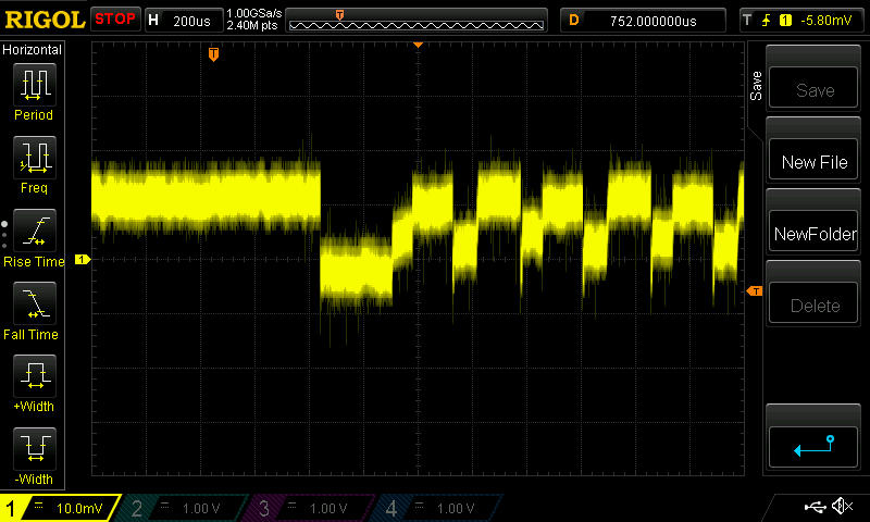
          So, purely eyeballing it, I'd say the Itead uses about, what, 13ma? The blob module is using maybe 20ma. Perhaps that difference in transmitter current, at least in part, explains the range difference that I observed.

          1 Reply Last reply
          0
          • NeverDieN Offline
            NeverDieN Offline
            NeverDie
            Hero Member
            wrote on last edited by NeverDie
            #111

            For further comparison, here are the measurements taken on the red module from earlier in the thread:

            red1.jpg

            red2.jpg

            red3.jpg

            red4.jpg

            Again, just eyeballing it, that looks like, what, maybe 23ma? Acually more than the blob module, it would seem.

            AWIA 1 Reply Last reply
            0
            • YveauxY Offline
              YveauxY Offline
              Yveaux
              Mod
              wrote on last edited by
              #112

              @NeverDIe Very intersting measurements dude!
              I have a gut feeling for some time that accurately measuring the transmission/reception current of a chip could be used to distinguish fake from real (and of course xray/boiling acid, which is impossible to do for the average consumer).
              Both the width and level of the current spikes are different for each module.
              Could you post the sketch used for measurement somewhere, so I can repeat your measurements?
              I have some 100% genuine Nordic modules, which can be used for reference.

              http://yveaux.blogspot.nl

              NeverDieN 1 Reply Last reply
              0
              • YveauxY Yveaux

                @NeverDIe Very intersting measurements dude!
                I have a gut feeling for some time that accurately measuring the transmission/reception current of a chip could be used to distinguish fake from real (and of course xray/boiling acid, which is impossible to do for the average consumer).
                Both the width and level of the current spikes are different for each module.
                Could you post the sketch used for measurement somewhere, so I can repeat your measurements?
                I have some 100% genuine Nordic modules, which can be used for reference.

                NeverDieN Offline
                NeverDieN Offline
                NeverDie
                Hero Member
                wrote on last edited by
                #113

                @Yveaux said:

                @NeverDIe Very intersting measurements dude!
                I have a gut feeling for some time that accurately measuring the transmission/reception current of a chip could be used to distinguish fake from real (and of course xray/boiling acid, which is impossible to do for the average consumer).
                Both the width and level of the current spikes are different for each module.
                Could you post the sketch used for measurement somewhere, so I can repeat your measurements?
                I have some 100% genuine Nordic modules, which can be used for reference.

                Here it is:

                
                /*
                 nRF24Sender Demo for RFToy
                 
                 This demo shows how to use RFToy to make a
                 wireless temperature sensor. This is the
                 sender module which transmits the current
                 temperature value to a receiver module. The
                 demo uses the Mirf library.
                 
                 This demo uses a 100K resistor and 100K
                 thermistor to form a simple temperature 
                 sensor. Pin A1 is used to read the value. 
                 The connection is:
                 VCC->100K->A1->thermistor->GND
                  
                 Written by Jonathan Goldin @ Rayshobby LLC
                 Nov 2014
                 For details, visit http://rayshobby.net/rftoy
                */
                
                #include <SPI.h>
                #include <Mirf.h>
                #include <nRF24L01.h>
                #include <MirfHardwareSpiDriver.h>
                #include <U8glib.h>
                
                U8GLIB_SSD1306_128X64 u8g(U8G_I2C_OPT_NONE);	// I2C / TWI 
                
                void setup(){
                  Serial.begin(115200);
                  Serial.println("Starting...");
                   
                  /*
                   Set ce and csn pins
                   */
                  
                  Mirf.cePin = 17;
                  Mirf.csnPin = 16;
                  
                  Mirf.spi = &MirfHardwareSpi;
                  Mirf.init();
                  
                  /*
                   * Configure reciving address.
                   */
                   
                  Mirf.setRADDR((byte *)"clie1");
                  
                  /*
                   * Set the payload length to sizeof(unsigned long) the
                   * return type of millis().
                   *
                   * NB: payload on client and server must be the same.
                   */
                   
                  //Mirf.payload = sizeof(long);
                  Mirf.payload = sizeof(long);  
                  /*
                   * Write channel and payload config then power up reciver.
                   */
                   
                  /*
                   * To change channel:
                   * 
                   * Mirf.channel = 10;
                   *
                   * NB: Make sure channel is legal in your area.
                   */
                   
                    // we use channel 90 as it is outside of WLAN bands 
                  // or channels used by wireless surveillance cameras 
                  //Mirf.channel = 90;
                  
                  Mirf.config();
                  
                    
                  //This register value is not remembered between power cycles.
                  //It defaults to 0x0F.
                  //It should be initialized each time if different than 0x0F.
                  Mirf.configRegister(RF_SETUP,0x07); //0x0F is 2mbps, max Tx power 
                                                      //0x07 is 1mbps, max Tx power
                                                      //0x2F is 250kbps, max Tx power.
                  Serial.println("OTA datarate set to  1Mbps.  Transmit Power set to Maximum.");
                  
                  // Read and print RF_SETUP
                 byte rf_setup = 0;
                 Mirf.readRegister( RF_SETUP, &rf_setup, sizeof(rf_setup) );
                 Serial.print( "rf_setup = " );
                 Serial.println( rf_setup, BIN );
                  // OLED
                  u8g.firstPage();
                  do{
                    uint8_t h;
                    u8g.setFont(u8g_font_10x20);
                    u8g.setFontRefHeightText();
                    u8g.setFontPosTop();
                    h = u8g.getFontAscent()-u8g.getFontDescent();
                    u8g.drawStr(29,(u8g.getHeight()-h)/2,"Tx Sender");
                  } 
                  while(u8g.nextPage());
                  Mirf.setTADDR((byte *)"serv1");
                  
                  Serial.write("Sending...\r\n"); 
                  delay(200);
                } // End of *Setup*
                
                
                long temp;
                  int temp1;
                  int temp2;
                  long timeTxSent;
                  long timeRxReceived;
                  long roundTrip;
                  byte age1=52;
                  byte age2=11;
                  long txCounter=0;
                  long matchCount=0;
                  long differentCount=0;
                  long lostCount=0;
                  long cumulativeRoundTrip=0;
                  long averageRoundTrip=0;
                  boolean packetLost=false;
                  float packetErrorRate=0;  //no errors yet, and maybe there never will be.
                  float lostPacketRate=0;  //no packets lost yet.
                  const int statusFrequency=500;  //How many iterations of main loop before printing status info.
                  long minRoundTrip=9999; //value will be driven down when program runs
                  long maxRoundTrip=0;  //value will be driven up when program runs
                  
                void loop(){
                   
                  txCounter++;
                  
                  temp = txCounter;  //getTemp(resistance);
                  
                  
                  timeTxSent=micros();
                  Mirf.send((byte *)&temp);  
                
                  while(Mirf.isSending()){
                  }
                
                  while ((micros() - timeTxSent) < 10000) {  //send at intervals of 10 milliseconds = 10,000 microseconds.
                  }
                 
                }  //End of main loop. 


                By the way, an RFToy is, from an IDE perspective, basically an 8Mhz Pro Mini.

                1 Reply Last reply
                0
                • YveauxY Offline
                  YveauxY Offline
                  Yveaux
                  Mod
                  wrote on last edited by Yveaux
                  #114

                  @NeverDie Thanks, but it has quite some dependencies: Mirf, MirfHardwareSpiDriver & u8glib... I guess I have to strip it first.
                  Furthermore, which nrf24 library did you use? The one from tmrh20?

                  http://yveaux.blogspot.nl

                  NeverDieN 1 Reply Last reply
                  0
                  • YveauxY Yveaux

                    @NeverDie Thanks, but it has quite some dependencies: Mirf, MirfHardwareSpiDriver & u8glib... I guess I have to strip it first.
                    Furthermore, which nrf24 library did you use? The one from tmrh20?

                    NeverDieN Offline
                    NeverDieN Offline
                    NeverDie
                    Hero Member
                    wrote on last edited by NeverDie
                    #115

                    @Yveaux said:

                    @NeverDie Thanks, but it has quite some dependencies: Mirf, MirfHardwareSpiDriver & u8glib...
                    Furthermore, which nrf24 library did you use? The one from tmrh20?

                    Mirf is the nrf24 library. It's what the RFToy example used, so I started with it, because it "just worked" out of the box. It just happens to be as far as I've gotten so far. I haven't yet converted to tmrh20, which would look more familiar to you.

                    The start loop is just a left-over from when I was doing echo testing. I removed the OLED for this test because it was a potential source of interference, so any code related to that could be deleted. Obviously, most of the global variables aren't needed either. As far as transmitting once every 10ms, all the action happens in the main loop, which is pretty simple. It's all fairly basic, because up until I actually did it, I wasn't sure I could even get a sufficiently noiseless signal to measure. Luckily, running the RFtoy on a coincell, and because it's compact and without dangling wires, made that possible.

                    So, in terms of which library to install, at the moment the easiest would be to load the RFToy library.

                    Or you can wait until I convert over to tmrh20, and then you can follow along that way. I'll need to do that to do the sleep measurement, and because TMRH20 is currently the leading library to use--at least that's what ManiacBug seems to think.

                    Or, if you already know tmrh20, you could code it yourself. The pseudo-code is quite simple:

                    1. Note the time in microseconds.
                    2. Send a packet with a 4 byte data payload (i.e. a LONG)
                    3. Wait until the current time exceeds the time in step 1 by at least 10,000 microseconds.
                    4. Goto Step 1

                    What I don't know are the defaults for ACK's and # of retries, if any, in Mirf and in TMRH20. Aside from that possible difference, I would imagine the current draws are going to be the same in either library, wouldn't you?

                    Perhaps the cleanest thing would be to skip the libraries entirely and do it all purely by register manipulations. That'd probably be a diversion from where I want to go, but maybe not a huge diversion. After all, how hard could it be? Since the guys doing the mysensors library for the attiny85 appear to be stuck, I may eventually have to do it that way if I want to use an attiny85 (which I do).

                    1 Reply Last reply
                    0
                    • YveauxY Offline
                      YveauxY Offline
                      Yveaux
                      Mod
                      wrote on last edited by
                      #116

                      @NeverDIe I committed a small sketch + NRF24 library which should essentially do the same as your sketch.
                      Please find it at https://github.com/Yveaux/NRF24_CurrentFingerprint.
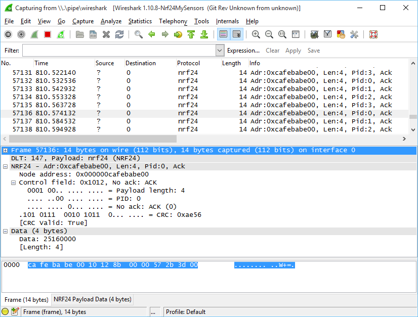
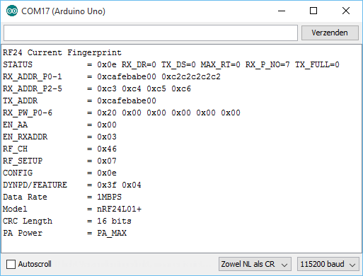
                      I verified its behavior using the NRF24 sniffer:

                      upload-c8184e00-67be-43e9-af4c-43242e39b830

                      Maybe we could compare register settings to be absolutely sure settings are identical:

                      upload-1418cfa7-5a26-40ff-9531-7221378b1875

                      Maybe you can repeat one of your measurements with this sketch, just to make sure we're measuring in the same way?

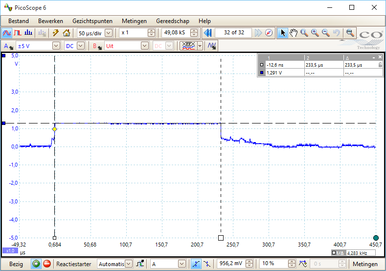
                      Currently I'm having a hard time measuring the actual current during transmit. I've not been able to get the individual spikes on the scope, not by using a uCurrent nor a single 1ohms resistor.

                      This is a uCurrent plot, set at 1mV/uA:

                      upload-2a6efb00-7e6a-462f-b3ce-f3a179b80ae6

                      That boils down to 1.3mA peak during transmission... That can't be right?!

                      http://yveaux.blogspot.nl

                      1 Reply Last reply
                      0
                      • YveauxY Offline
                        YveauxY Offline
                        Yveaux
                        Mod
                        wrote on last edited by Yveaux
                        #117

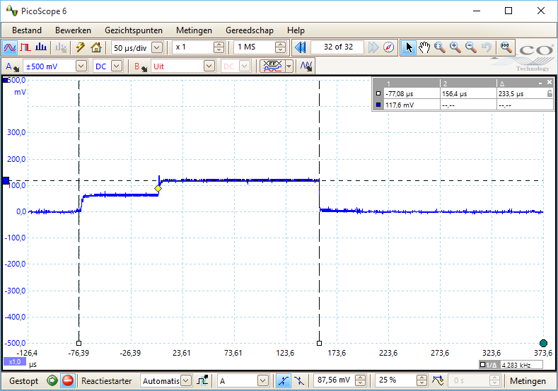
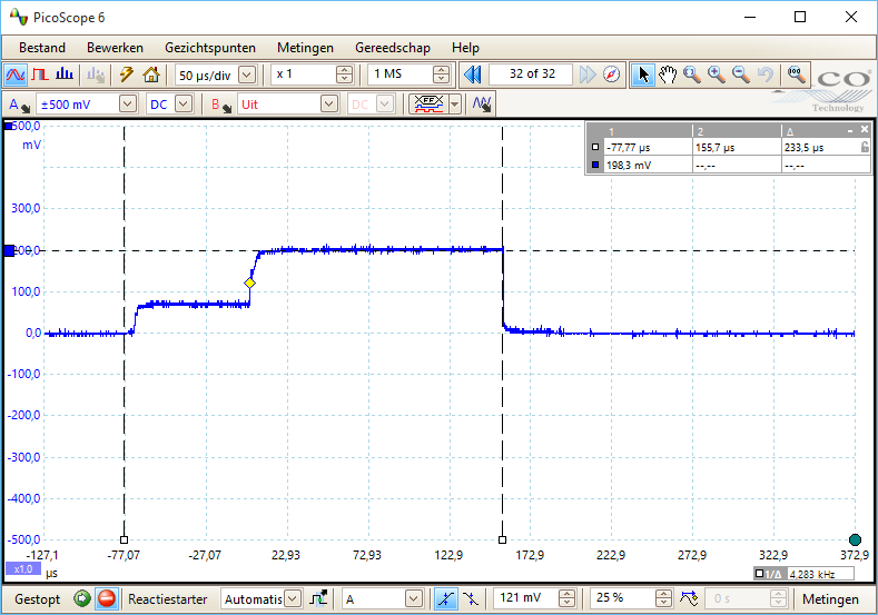
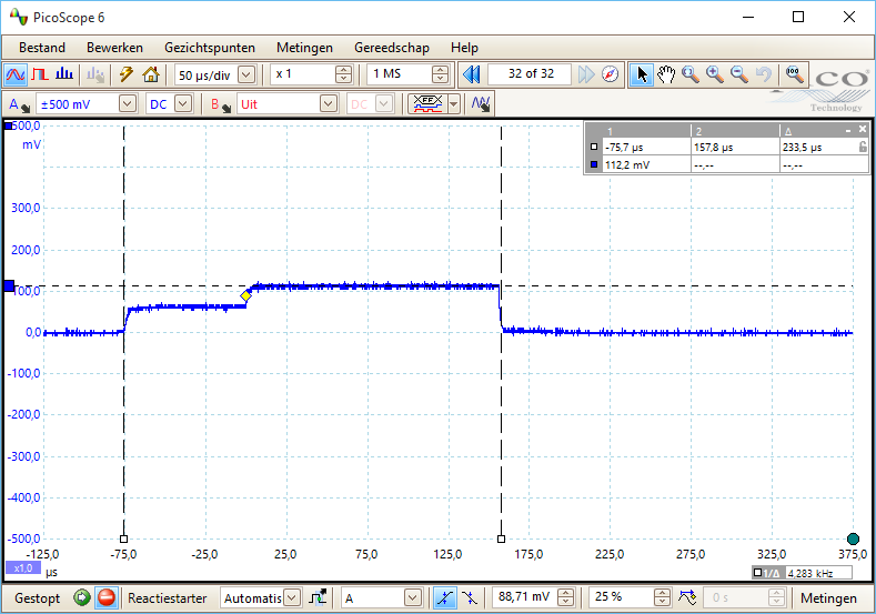
                        Small update: using a 10ohms resitor, the current profile looks like:

                        upload-fe4a379b-9a19-4e5d-ba78-086f1906e86b

                        10mV/mA, so my module peaks at 11.7 mA. This module contains a 100% genuine Nordic nRF24L01+.

                        A module containing a proven fake nRF24L01+ (marked 1242AF), reveals following current profile:

                        upload-916e4d87-e4f8-4262-bef9-fd82dbfbca1d

                        This one peaks at 19.8mA !!

                        Register settings and on-air packets are identical.

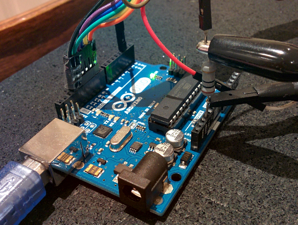
                        For completenes my measurement setup:

                        • Lab supply, which powers USB isolator
                        • USB isolator between PC & Arduino (otherwise ground-loops mess things up when using a USB scope on the same PC)
                        • 10 ohms resistor

                        upload-3ba85b97-4e4a-40af-86f6-00f38b5d545b

                        http://yveaux.blogspot.nl

                        1 Reply Last reply
                        0
                        • NeverDieN Offline
                          NeverDieN Offline
                          NeverDie
                          Hero Member
                          wrote on last edited by NeverDie
                          #118

                          That's great!

                          The red module I tested (above) also used 1242AF. So, asuming the NRF chip in the Itead is genuine (which seems increasingly likely), then proportionately speaking, we're getting similar measurements.

                          Aside from the Picoscope, what is your test setup? You don't seem to be experiencing the fat scope lines that I am. Where is the NRF module in your photo? Is it being levitated by the wires in the photo? I'm surprised the wires don't seem to be picking up noise.

                          YveauxY 1 Reply Last reply
                          0
                          • NeverDieN NeverDie

                            That's great!

                            The red module I tested (above) also used 1242AF. So, asuming the NRF chip in the Itead is genuine (which seems increasingly likely), then proportionately speaking, we're getting similar measurements.

                            Aside from the Picoscope, what is your test setup? You don't seem to be experiencing the fat scope lines that I am. Where is the NRF module in your photo? Is it being levitated by the wires in the photo? I'm surprised the wires don't seem to be picking up noise.

                            YveauxY Offline
                            YveauxY Offline
                            Yveaux
                            Mod
                            wrote on last edited by Yveaux
                            #119

                            @NeverDie I added it to my previous post.

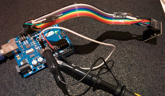
                            Overview of whole setup:

                            upload-f518c490-0a0f-4376-899d-14af8966192a

                            I never had issues with the wires picking up noise; at least not enough to distort communication. They're approx. 20cm long.

                            One more:

                            upload-972e72b1-ed33-4440-8f4f-602ac91263bf

                            Module with nRF marked 1322DQ, supposedly genuine.
                            Also 11.2mA

                            Tried it with another, random 1242AF, which gave 21.4mA

                            http://yveaux.blogspot.nl

                            1 Reply Last reply
                            1
                            • NeverDieN Offline
                              NeverDieN Offline
                              NeverDie
                              Hero Member
                              wrote on last edited by
                              #120

                              Exactly which USB isolator are you using? Sounds like I should get myself a couple in case I ever need to do this again.

                              YveauxY 1 Reply Last reply
                              0
                              • NeverDieN NeverDie

                                Exactly which USB isolator are you using? Sounds like I should get myself a couple in case I ever need to do this again.

                                YveauxY Offline
                                YveauxY Offline
                                Yveaux
                                Mod
                                wrote on last edited by Yveaux
                                #121

                                @NeverDie A Chinese clone of this circuit: https://www.circuitsathome.com/measurements/usb-isolator
                                The power socket is used to power the isolated USB side.
                                Beware this isolator ca only handle FullSpeed (12MBit/s), so not USB 2.0 HighSpeed (480MBit/s).
                                This prevents me from isolating my USB scope with it...

                                http://yveaux.blogspot.nl

                                1 Reply Last reply
                                1
                                • NeverDieN Offline
                                  NeverDieN Offline
                                  NeverDie
                                  Hero Member
                                  wrote on last edited by NeverDie
                                  #122

                                  Your setup roughly resembles my first attempt, where I was also using an Uno. However, I was overwhelmed with noise, which made me try the RFToy. I wasn't using isolators, though. I'm glad you got yours working, because it means that just about anyone with isolators and a scope can maybe do this test for themselves. As illustrated by you, the setup if pretty easy to follow. Good job!

                                  P.S. Does using ribbon cable, as you are doing, rather than individual Dupont wires (as I did when I tried using the Uno) also help with controlling noise?

                                  1 Reply Last reply
                                  0
                                  • NeverDieN Offline
                                    NeverDieN Offline
                                    NeverDie
                                    Hero Member
                                    wrote on last edited by
                                    #123

                                    Interestingly, the USB cable that came with my Rigol has big ferrite cores on both ends of it. So, that probably helps as well.

                                    1 Reply Last reply
                                    0
                                    • NeverDieN Offline
                                      NeverDieN Offline
                                      NeverDie
                                      Hero Member
                                      wrote on last edited by
                                      #124

                                      Actually, you could just power that arduino using a battery. Right? Having the isolator is nice, in that you can monitor what's happening, but not strictly necessary.

                                      So, really, I guess anyone with an o-scope can do this test, which is great!

                                      YveauxY 1 Reply Last reply
                                      0
                                      • NeverDieN NeverDie

                                        Actually, you could just power that arduino using a battery. Right? Having the isolator is nice, in that you can monitor what's happening, but not strictly necessary.

                                        So, really, I guess anyone with an o-scope can do this test, which is great!

                                        YveauxY Offline
                                        YveauxY Offline
                                        Yveaux
                                        Mod
                                        wrote on last edited by
                                        #125

                                        @NeverDie correct!
                                        With some simple hardware the uno could measure the current by itself and determine the maximum current used!
                                        This has potential!

                                        http://yveaux.blogspot.nl

                                        NeverDieN 1 Reply Last reply
                                        0
                                        • YveauxY Yveaux

                                          @NeverDie correct!
                                          With some simple hardware the uno could measure the current by itself and determine the maximum current used!
                                          This has potential!

                                          NeverDieN Offline
                                          NeverDieN Offline
                                          NeverDie
                                          Hero Member
                                          wrote on last edited by NeverDie
                                          #126

                                          @Yveaux said:

                                          @NeverDie correct!
                                          With some simple hardware the uno could measure the current by itself and determine the maximum current used!
                                          This has potential!

                                          Which hardware would that be?

                                          YveauxY 1 Reply Last reply
                                          0
                                          Reply
                                          • Reply as topic
                                          Log in to reply
                                          • Oldest to Newest
                                          • Newest to Oldest
                                          • Most Votes


                                          16

                                          Online

                                          11.7k

                                          Users

                                          11.2k

                                          Topics

                                          113.0k

                                          Posts


                                          Copyright 2019 TBD   |   Forum Guidelines   |   Privacy Policy   |   Terms of Service
                                          • Login

                                          • Don't have an account? Register

                                          • Login or register to search.
                                          • First post
                                            Last post
                                          0
                                          • MySensors
                                          • OpenHardware.io
                                          • Categories
                                          • Recent
                                          • Tags
                                          • Popular