Which are the *best* NRF24L01+ modules?


  • Hero Member

    @Zeph said:

    I'm wondering about the blobs that worked better than genuine/iTead nRF24L01+ (@1Mhz), is that because they are the higher powered clones? What's the power supply drain during transmit, compared to genuine?

    I wonder about that as well. For instance, the Si24R1 supposedly has a max transmit power of 7dB, which is well above the maximum of 0dB for a true NRF24L01+.

    Unfortunately, I'm not presently setup to measure that, so I don't know the answer. However, the range and performance is simply so much better that I'm guessing that might be the reason for it. And if that is the reason, then great: I can dial back the Tx power when it's not needed, but it's there when it is needed.

    However, I doubt it's the whole story. I also tried some high power modules with PA + LNA that I got from IC Station. These are the same modules that got top rank by a guy who reviewed a whole bunch of modules:
    https://www.youtube.com/watch?v=gtM832Z0ujE
    Guess what? They don't perform as well as the blob modules! At least not in my indoor test setup environment. They cost a lot more too than the blob modules. It's difficult to fathom.


  • Hero Member

    The packet loss info could be useful.

    The Round Trip Time (RTT) testing would seem to make sense only if using ESB with ack and auto-retry is enabled, and there are errors which require one or more retries. Without retry, the packet should either be received in a fixed amount of time, or not received; the nRF24L01+ doesn't "think it over" for a while before deciding on weak packets. So it's just a disguised packet loss test, but harder to interpret.

    If we want to test link quality, I think packet loss without retries is a the measurement.

    And there should often be different packet losses with short and long packets. Long packets are more likely to get corrupted and lost (failing the CRC test).


  • Hero Member

    @NeverDie So you've received two orders of blob modules which work well, from different sources?

    Where did you order them from? I'm interested.


  • Hero Member

    @GIEL said:

    @NeverDie

    NORDIC has on their Website the option to raise questions (MyPage) which are handled by their Tech Support Team. Normally they reply fast.

    It worked! I provided them with photos of the chips from the Itead modules. Here is their reply:

    "
    Hi,

    We are not aware of any fake chips with these markings as of today, but if you want us to investigate further we need samples here for x-ray.

    It is also possible that the modules has not been properly tuned (e.g. matching network and antenna) during development of the module. You will need access to a spectrum and network analyzer for proper measurement.

    Best regards,

    Kenneth"

    I need to move on. It is not worth my time to pursue this further.


  • Hero Member

    @NeverDie oh come on! Do it! Do it! 😄


  • Hero Member

    @Zeph said:

    @NeverDie So you've received two orders of blob modules which work well, from different sources?

    Where did you order them from? I'm interested.

    I originally received two modules from: http://rayshobby.net/rftoy/ when I purchased my RFToy.

    I received 10 from http://www.ebay.com/itm/301378218320, of which I've tested two, and they seem the same.

    These I haven't tried: http://www.ebay.com/itm/301402792434 but looking at the photos they look the same to me.

    So, for the NRF24L01+, if you can call it that, this "blob module" is my final choice. In my rough-and-ready testing, it stood out from the rest. If you decide to get it, I'd be curious if you, or anyone, can figure out what it actually is. It can't do 250Kbps. I anticipate I would run it at 1Mbps only.

    If it weren't for the RFM69HW, I would buy more. I'm waiting to see whether I like it more.


  • Hero Member

    Looking at the datasheet for the RFM69, I notice the maximum datarate is 300kbps. So, at least on paper, I get the impression the NRF24L01+ wins on power efficiency, but the RFM69 can offer greater range. Is that right? Is that the main tradeoff between the two?


  • Hero Member

    The RFM69x operates in one of three smaller frequency bands (ie: fewer available frequencies): 433MHz, 868 MHz (Europe), 915 MHz (US).

    While there are supposed to be scores of independent channels for the nRF24 on the wider 2.4GHz band, there isn't as much room on the lower frequency bands. So 300 KBps is more of a theoretical limit; mostly the RFM69 is used for lower bit rates than that, with correspondingly lower bandwidth - and thus higher range! Unlike the nRF, you can trade off bit rate & bandwidth vs range (at any given power).

    For most sensor networks, I think the RFM69 will have plenty of data bandwidth and better range (at say 56Kbps or so). For a good example, see the JeeNodes (which used the RFM12B but are migrating to the RFM69x which fits the same niche but is a better chip). JeeNodes fit a niche very similar to MySensors in that there are distributed sensor nodes communicating with a central hub, with some of the sensor nodes sleeping most of the time to save battery power. (JeeNodes are not as well integrated into common Home Automation systems, but we are now talking more about hardware and protocols).

    I also use the nRF for holiday lighting control, which is more bandwidth hungry. For that the higher speeds are required. In this case a master is blasting data as fast as it can to one or more slaves; the slaves don't need to respond much, and if they do they can be polled with the Master so the master doesn't broadcast at the same time. (If using nRF for MySensors too, obviously they need to be on different channels).

    There is some usefulness to me in using nRF24L01+ for both, so the same node hardware can potentially be re-purposed; it's only a firmware (and channel) change to switch between these networks. But I'm rethinking this and wondering about switching sensors to the RFM68x.

    I'm not sure about power efficiency. An analysis will depend on how often the node needs to be powered up and for how long, as well as the sleep current. JeeNodes are also pretty careful about power.


  • Hero Member

    @NeverDie

    So, for the NRF24L01+, if you can call it that, this "blob module" is my final choice.

    They are sounding potentially attractive. Here is some of what I am wondering.

    1. Do they take more power when transmitting? When receiving? (Should be fairly easy to test) When sleeping? (Harder, needs micropower sensor)

    2. Do they test (via registers) as nRF24L01 or nRF24L01+? And in particular, do they implement all the plus features (like ESB mode) other than the missing 250 Kbps data rate?

    3. Are they compatible over the air with the Nordic chips (at 1Mbps/2Mbps)? In general, and in terms of using ESB mode. At least one clone/derivative chip got the NoAck bit (as sent over the air) reversed from Nordic, due to an error in the Nordic datasheet. (We don't see that in the registers, it only shows up in the OTA packet).

    It would be good to be compatible with Nordic (and good clones), so that (1) we can swap in/out with other nRF chips we already have or purchase in the future and (2) in particular we can use the higher powered LNA+PA+antenna versions for a gateway or hub, which are not available in blob form AFAIK.

    Do you have any answers to any of these yet? Anybody else? If they have ESB and are compatible OTA with Nordic, I think they are very attractive; the power usage is a secondary concern, and only for some nodes.


  • Hero Member

    I don't at present know any of those answers. However, I am interested in power consumed. Also, at present I'm less concerned about interoperability than I am about range and not having to aim the antenna so precisely.


  • Hero Member

    @Zeph said:

    @NeverDie

    So, for the NRF24L01+, if you can call it that, this "blob module" is my final choice.

    They are sounding potentially attractive. Here is some of what I am wondering.

    1. Do they take more power when transmitting? When receiving? (Should be fairly easy to test) When sleeping? (Harder, needs micropower sensor)

    2. Do they test (via registers) as nRF24L01 or nRF24L01+? And in particular, do they implement all the plus features (like ESB mode) other than the missing 250 Kbps data rate?

    3. Are they compatible over the air with the Nordic chips (at 1Mbps/2Mbps)? In general, and in terms of using ESB mode. At least one clone/derivative chip got the NoAck bit (as sent over the air) reversed from Nordic, due to an error in the Nordic datasheet. (We don't see that in the registers, it only shows up in the OTA packet).

    It would be good to be compatible with Nordic (and good clones), so that (1) we can swap in/out with other nRF chips we already have or purchase in the future and (2) in particular we can use the higher powered LNA+PA+antenna versions for a gateway or hub, which are not available in blob form AFAIK.

    Do you have any answers to any of these yet? Anybody else? If they have ESB and are compatible OTA with Nordic, I think they are very attractive; the power usage is a secondary concern, and only for some nodes.

    @Zeph: Regarding #2: What is ESB mode? To what degree does the mysensors code rely on those things being true? i.e. do certain clone/fake chips "break" the mysensors code, or do they just run less efficiently?

    So far I haven't noticed incompatibility between the blob modules and other modules. I haven't extensively tested, though, so it's more of a casual observation. The data seems to get through. That said, I'm going to use only blob modules, so it's a moot issue to me. If it were a concern for you, they're cheap enough you could probably just replace whatever modules you have with blob modules, and then those potential issues disappear. Ironically, the only way to be certain all your modules are of the same type may be to use blob modules! Otherwise, as you outlined earlier, it's really hard to know what chip you actually have on any given module. I have less confidence in how randomly different chips might interoperate than when chps are all of one type, whatever that may be.

    I'm going to switchover from using Mirf (which got me started) to the same library mySensors uses :tmrh20. Then I'll be better able to run more detailed tests that are directly relevant. Either before or after that I'll try to measure power consumption, especially transmit power.


  • Admin

    Got the microscope today. This is a closeup of the genuine NRF-chip.

    PICT0001.JPG

    PICT0003.JPG


  • Hi everyone!

    I bought some NRF24L01+ that have the Range Extension chip RFaxis RFX2401C

    I'm curious to see how they perform 🙂

    And for that I'm thinking in rewriting the RFToy Sender/Receiver examples with the MySensor libraries.
    This will allow me to learn about the MySensor libraries and also to test the "performance" of the RF modules with different configurations.

    What do you think? Let me know if you're interested in such code.

    Regards


  • Hero Member

    @Daniel-Oliveira said:

    Hi everyone!

    I bought some NRF24L01+ that have the Range Extension chip RFaxis RFX2401C

    I'm curious to see how they perform 🙂

    And for that I'm thinking in rewriting the RFToy Sender/Receiver examples with the MySensor libraries.
    This will allow me to learn about the MySensor libraries and also to test the "performance" of the RF modules with different configurations.

    What do you think? Let me know if you're interested in such code.

    Regards

    Yes, definitely! I'll also be very interested to hear about the performance of your range extended modules.


  • Hero Member

    I took a quick stab just now at using a Dave Jones uCurrent and an oscilliscope to measure the current on an NRF24L01+, but there was too much noise. I suspect long wires are contributing to the problem. I'm inclined to think some kind of onboard measurement by the arduino itself is the way to go, as then the wire lengths are short. Not sure how other people are rigging to do it, but so far measuring NRF power consumption seems a lot easier said than done.


  • Mod

    @NeverDie just some tips when measuring small currents:

    • use a stable power supply (e.g lab supply). Don't power from you pc or cheap switching powersupply.
    • twist the leads to the current.
    • use your scope to filter noise or add a lowpass filter using a capicitor+resistor on the signal going from the ucurrent to your scope

  • Hero Member

    @Yveaux said:

    @NeverDie just some tips when measuring small currents:

    • use a stable power supply (e.g lab supply). Don't power from you pc or cheap switching powersupply.
    • twist the leads to the current.
    • use your scope to filter noise or add a lowpass filter using a capicitor+resistor on the signal going from the ucurrent to your scope

    Thanks! Those are useful suggestions on how to proceed.

    On my first attempt last night I used an Arduino Uno to drive the NRF24L01+. I eventually noticed that even without plugging the USB cable into my computer that the USB cable was a big source of noise when plugged into the Uno. When I did plug the USB cable into my computer, the noise got much worse. So, the USB cable has got to go.

    New plan for the second attempt::

    • Use an RFToy, instead of Uno, because it's a more compact way to plug-in the NRF24L01+ without having wires dangling all over, and because it can run off a coin cell battery, again without wires.

    • Plug the NRF24L01+ into "tall" female header pins, and then plug those into the usual 2x4 header on the RFToy. Why? Because the leg of the tall VCC header pin I'm going to snip and (hopefully) replace with a 1 ohm sense resister. With luck there will be enough room on either side of the inline sense resister to connect up the oscilloscope and thereby do measurements without introducing long wires that might pick up noise.


  • Hero Member

    BTW, I notice ManiacBug measures transmitter current with just a $50 multimeter and setting "endless trasmitter" mode. https://maniacbug.wordpress.com/2011/10/19/sensor-node/

    Not sure how accurate that is though.


  • Hero Member

    Lastly, I notice these "Noise Cancelling Techniques" from an Attiny datasheet, regtarding ADC measurements:
    "Digital circuitry inside and outside the device generates EMI which might affect the accuracy of
    analog measurements. When conversion accuracy is critical, the noise level can be reduced by
    applying the following techniques:
    • Keep analog signal paths as short as possible.
    • Make sure analog tracks run over the analog ground plane.
    • Keep analog tracks well away from high-speed switching digital tracks.
    • If any port pin is used as a digital output, it mustn’t switch while a conversion is in progress.
    • Place bypass capacitors as close to VCC and GND pins as possible."


  • Hero Member

    @NeverDie said:

    @Zeph said:

    @NeverDie

    So, for the NRF24L01+, if you can call it that, this "blob module" is my final choice.

    They are sounding potentially attractive. Here is some of what I am wondering.

    1. Do they take more power when transmitting? When receiving? (Should be fairly easy to test) When sleeping? (Harder, needs micropower sensor)

    2. Do they test (via registers) as nRF24L01 or nRF24L01+? And in particular, do they implement all the plus features (like ESB mode) other than the missing 250 Kbps data rate?

    3. Are they compatible over the air with the Nordic chips (at 1Mbps/2Mbps)? In general, and in terms of using ESB mode. At least one clone/derivative chip got the NoAck bit (as sent over the air) reversed from Nordic, due to an error in the Nordic datasheet. (We don't see that in the registers, it only shows up in the OTA packet).

    It would be good to be compatible with Nordic (and good clones), so that (1) we can swap in/out with other nRF chips we already have or purchase in the future and (2) in particular we can use the higher powered LNA+PA+antenna versions for a gateway or hub, which are not available in blob form AFAIK.

    Do you have any answers to any of these yet? Anybody else? If they have ESB and are compatible OTA with Nordic, I think they are very attractive; the power usage is a secondary concern, and only for some nodes.

    @Zeph: Regarding #2: What is ESB mode?

    Enhanced ShockBurst, which is a mode added to the plus version by Nordic (nRF24L01+). Many of the clones and derivatives have it, some may not. It adds automatic ack and retry, and perhaps other features.

    @hek is ESB mode still used in MySensors?

    So far I haven't noticed incompatibility between the blob modules and other modules. I haven't extensively tested, though, so it's more of a casual observation. The data seems to get through. That said, I'm going to use only blob modules, so it's a moot issue to me. If it were a concern for you, they're cheap enough you could probably just replace whatever modules you have with blob modules, and then those potential issues disappear.

    Have you found compatible blob modules with external antennas and/or LNA+PA (Low Noise Amplifier + Power Amplifier)?

    Ironically, the only way to be certain all your modules are of the same type may be to use blob modules!

    Until a new blob module type shows up.

    Otherwise, as you outlined earlier, it's really hard to know what chip you actually have on any given module. I have less confidence in how randomly different chips might interoperate than when chps are all of one type, whatever that may be.

    People here and elsewhere have had a lot of success in interoperation. However, that could be becoming more difficult, if too many fake chips get on the market.

    BTW - I consider an openly described "nRF24L01+ compatible" chip to be a "derivative" if it openly modifies or extends the Nordic functions, a "clone" if it attempts to exactly mimic the Nordic chips. A "fake" is mislabeled and deceptive rather than being openly described as not Nordic.

    I'm going to switchover from using Mirf (which got me started) to the same library mySensors uses :tmrh20. Then I'll be better able to run more detailed tests that are directly relevant. Either before or after that I'll try to measure power consumption, especially transmit power.

    Good idea. I think TMRH20 has the best RF24 fork, and I've contributed slightly to it in its early days.

    I look forward to your measurements. For battery operation with long sleep periods, the sleep current is also important.

    If your module has higher RF transmit power (as I suspect), it might also be interesting to see what the current drain is when you drop the power a notch (ie: bring it closer to the Nordic part's RF output). The ideal might be if it can be run at about the same RF power as Nordic with similar PS current, OR could be boosted for more RF power at the cost of more PS current.

    Bu the way, you might have a version which can boost its power still further. For example, the Si24R01 has a default boost of about 2-3 dBm over the Nordic, but can be set for 7 dBm! See https://github.com/solarkennedy/equail/tree/master/Libraries/RF24

    Since transmit power is likely over 10mA you may be able to measure that without a MicroPower device. But you'll need such a device to measure sleep currents.


  • Hero Member

    @Zeph said:

    Have you found compatible blob modules with external antennas and/or LNA+PA (Low Noise Amplifier + Power Amplifier)?

    Interesting idea. I don't recollect seeing any LNA+PA modules with blobs on them, but then again I haven't tried looking for such a thing. At least so far the simple blob module appears to have all the range I need.


  • Hero Member

    @Zeph said:

    For battery operation with long sleep periods, the sleep current is also important.

    Good point. Noise might present a problem with measuring it, but I'll make an attempt. Perhaps a regular multimeter would be good enough for that, since (presumably) it would average any spikes? The result might be higher than the true number, and so be a worst case number. That's possibly OK though: if it turns out the worst case number is acceptable, then all is good.


  • Hero Member

    @Zeph said:

    I think TMRH20 has the best RF24 fork, and I've contributed slightly to it in its early days.

    Excellent! In that case, do you happen to know off the top of your head: what's the simplest method or function call in TMRH20 for putting the NRF24L01+ to sleep? If I don't have to research that, I can jump ahead to taking a measurement of it sleeping, as per the above.


  • Hero Member

    @NeverDie
    http://tmrh20.github.io/RF24/classRF24.html#aa0a51923a09ba4f3478aba9be0f8a6a1

    You are going to need your Davy Jones uCurrent to measure sleeping current!


  • Hero Member

    So, here are the current measurements on the blob module. I used a 1 ohm sense resister, so 1mv=1ma.

    I wrote a short script to transmit a packet once every 10 milliseconds:
    oscope1.jpg

    Now I'll zoom in progressively so you can see for yourself what the current is:
    oscope2.jpg

    oscope3.jpg

    oscope4.jpg

    Doing this measurement is the first time I've ever used an oscilliscope (a Rigole 1054Z). Because the lines are kinda thick (noise, I guess), what would you say the current draw is during a transmission?

    In this case, there is no echo receiver, and so whatever gets sent isn't received by anything.


  • Hero Member

    Here is the simple test jig that I made, using a 1 ohm resistor:
    jig.jpg

    Here it is mounted on the RFToy:
    mounted.jpg

    Here is how I hooked up the oscilloscope probe:
    hookup.jpg


  • Hero Member

    For comparison, here are the measurements taken on an ITEAD module:

    itead1.jpg

    itead2.jpg

    itead3.jpg

    itead4.jpg

    So, purely eyeballing it, I'd say the Itead uses about, what, 13ma? The blob module is using maybe 20ma. Perhaps that difference in transmitter current, at least in part, explains the range difference that I observed.


  • Hero Member

    For further comparison, here are the measurements taken on the red module from earlier in the thread:

    red1.jpg

    red2.jpg

    red3.jpg

    red4.jpg

    Again, just eyeballing it, that looks like, what, maybe 23ma? Acually more than the blob module, it would seem.


  • Mod

    @NeverDIe Very intersting measurements dude!
    I have a gut feeling for some time that accurately measuring the transmission/reception current of a chip could be used to distinguish fake from real (and of course xray/boiling acid, which is impossible to do for the average consumer).
    Both the width and level of the current spikes are different for each module.
    Could you post the sketch used for measurement somewhere, so I can repeat your measurements?
    I have some 100% genuine Nordic modules, which can be used for reference.


  • Hero Member

    @Yveaux said:

    @NeverDIe Very intersting measurements dude!
    I have a gut feeling for some time that accurately measuring the transmission/reception current of a chip could be used to distinguish fake from real (and of course xray/boiling acid, which is impossible to do for the average consumer).
    Both the width and level of the current spikes are different for each module.
    Could you post the sketch used for measurement somewhere, so I can repeat your measurements?
    I have some 100% genuine Nordic modules, which can be used for reference.

    Here it is:

    
    /*
     nRF24Sender Demo for RFToy
     
     This demo shows how to use RFToy to make a
     wireless temperature sensor. This is the
     sender module which transmits the current
     temperature value to a receiver module. The
     demo uses the Mirf library.
     
     This demo uses a 100K resistor and 100K
     thermistor to form a simple temperature 
     sensor. Pin A1 is used to read the value. 
     The connection is:
     VCC->100K->A1->thermistor->GND
      
     Written by Jonathan Goldin @ Rayshobby LLC
     Nov 2014
     For details, visit http://rayshobby.net/rftoy
    */
    
    #include <SPI.h>
    #include <Mirf.h>
    #include <nRF24L01.h>
    #include <MirfHardwareSpiDriver.h>
    #include <U8glib.h>
    
    U8GLIB_SSD1306_128X64 u8g(U8G_I2C_OPT_NONE);	// I2C / TWI 
    
    void setup(){
      Serial.begin(115200);
      Serial.println("Starting...");
       
      /*
       Set ce and csn pins
       */
      
      Mirf.cePin = 17;
      Mirf.csnPin = 16;
      
      Mirf.spi = &MirfHardwareSpi;
      Mirf.init();
      
      /*
       * Configure reciving address.
       */
       
      Mirf.setRADDR((byte *)"clie1");
      
      /*
       * Set the payload length to sizeof(unsigned long) the
       * return type of millis().
       *
       * NB: payload on client and server must be the same.
       */
       
      //Mirf.payload = sizeof(long);
      Mirf.payload = sizeof(long);  
      /*
       * Write channel and payload config then power up reciver.
       */
       
      /*
       * To change channel:
       * 
       * Mirf.channel = 10;
       *
       * NB: Make sure channel is legal in your area.
       */
       
        // we use channel 90 as it is outside of WLAN bands 
      // or channels used by wireless surveillance cameras 
      //Mirf.channel = 90;
      
      Mirf.config();
      
        
      //This register value is not remembered between power cycles.
      //It defaults to 0x0F.
      //It should be initialized each time if different than 0x0F.
      Mirf.configRegister(RF_SETUP,0x07); //0x0F is 2mbps, max Tx power 
                                          //0x07 is 1mbps, max Tx power
                                          //0x2F is 250kbps, max Tx power.
      Serial.println("OTA datarate set to  1Mbps.  Transmit Power set to Maximum.");
      
      // Read and print RF_SETUP
     byte rf_setup = 0;
     Mirf.readRegister( RF_SETUP, &rf_setup, sizeof(rf_setup) );
     Serial.print( "rf_setup = " );
     Serial.println( rf_setup, BIN );
      // OLED
      u8g.firstPage();
      do{
        uint8_t h;
        u8g.setFont(u8g_font_10x20);
        u8g.setFontRefHeightText();
        u8g.setFontPosTop();
        h = u8g.getFontAscent()-u8g.getFontDescent();
        u8g.drawStr(29,(u8g.getHeight()-h)/2,"Tx Sender");
      } 
      while(u8g.nextPage());
      Mirf.setTADDR((byte *)"serv1");
      
      Serial.write("Sending...\r\n"); 
      delay(200);
    } // End of *Setup*
    
    
    long temp;
      int temp1;
      int temp2;
      long timeTxSent;
      long timeRxReceived;
      long roundTrip;
      byte age1=52;
      byte age2=11;
      long txCounter=0;
      long matchCount=0;
      long differentCount=0;
      long lostCount=0;
      long cumulativeRoundTrip=0;
      long averageRoundTrip=0;
      boolean packetLost=false;
      float packetErrorRate=0;  //no errors yet, and maybe there never will be.
      float lostPacketRate=0;  //no packets lost yet.
      const int statusFrequency=500;  //How many iterations of main loop before printing status info.
      long minRoundTrip=9999; //value will be driven down when program runs
      long maxRoundTrip=0;  //value will be driven up when program runs
      
    void loop(){
       
      txCounter++;
      
      temp = txCounter;  //getTemp(resistance);
      
      
      timeTxSent=micros();
      Mirf.send((byte *)&temp);  
    
      while(Mirf.isSending()){
      }
    
      while ((micros() - timeTxSent) < 10000) {  //send at intervals of 10 milliseconds = 10,000 microseconds.
      }
     
    }  //End of main loop. 


    By the way, an RFToy is, from an IDE perspective, basically an 8Mhz Pro Mini.


  • Mod

    @NeverDie Thanks, but it has quite some dependencies: Mirf, MirfHardwareSpiDriver & u8glib... I guess I have to strip it first.
    Furthermore, which nrf24 library did you use? The one from tmrh20?


  • Hero Member

    @Yveaux said:

    @NeverDie Thanks, but it has quite some dependencies: Mirf, MirfHardwareSpiDriver & u8glib...
    Furthermore, which nrf24 library did you use? The one from tmrh20?

    Mirf is the nrf24 library. It's what the RFToy example used, so I started with it, because it "just worked" out of the box. It just happens to be as far as I've gotten so far. I haven't yet converted to tmrh20, which would look more familiar to you.

    The start loop is just a left-over from when I was doing echo testing. I removed the OLED for this test because it was a potential source of interference, so any code related to that could be deleted. Obviously, most of the global variables aren't needed either. As far as transmitting once every 10ms, all the action happens in the main loop, which is pretty simple. It's all fairly basic, because up until I actually did it, I wasn't sure I could even get a sufficiently noiseless signal to measure. Luckily, running the RFtoy on a coincell, and because it's compact and without dangling wires, made that possible.

    So, in terms of which library to install, at the moment the easiest would be to load the RFToy library.

    Or you can wait until I convert over to tmrh20, and then you can follow along that way. I'll need to do that to do the sleep measurement, and because TMRH20 is currently the leading library to use--at least that's what ManiacBug seems to think.

    Or, if you already know tmrh20, you could code it yourself. The pseudo-code is quite simple:

    1. Note the time in microseconds.
    2. Send a packet with a 4 byte data payload (i.e. a LONG)
    3. Wait until the current time exceeds the time in step 1 by at least 10,000 microseconds.
    4. Goto Step 1

    What I don't know are the defaults for ACK's and # of retries, if any, in Mirf and in TMRH20. Aside from that possible difference, I would imagine the current draws are going to be the same in either library, wouldn't you?

    Perhaps the cleanest thing would be to skip the libraries entirely and do it all purely by register manipulations. That'd probably be a diversion from where I want to go, but maybe not a huge diversion. After all, how hard could it be? Since the guys doing the mysensors library for the attiny85 appear to be stuck, I may eventually have to do it that way if I want to use an attiny85 (which I do).


  • Mod

    @NeverDIe I committed a small sketch + NRF24 library which should essentially do the same as your sketch.
    Please find it at https://github.com/Yveaux/NRF24_CurrentFingerprint.
    I verified its behavior using the NRF24 sniffer:

    upload-c8184e00-67be-43e9-af4c-43242e39b830

    Maybe we could compare register settings to be absolutely sure settings are identical:

    upload-1418cfa7-5a26-40ff-9531-7221378b1875

    Maybe you can repeat one of your measurements with this sketch, just to make sure we're measuring in the same way?

    Currently I'm having a hard time measuring the actual current during transmit. I've not been able to get the individual spikes on the scope, not by using a uCurrent nor a single 1ohms resistor.

    This is a uCurrent plot, set at 1mV/uA:

    upload-2a6efb00-7e6a-462f-b3ce-f3a179b80ae6

    That boils down to 1.3mA peak during transmission... That can't be right?!


  • Mod

    Small update: using a 10ohms resitor, the current profile looks like:

    upload-fe4a379b-9a19-4e5d-ba78-086f1906e86b

    10mV/mA, so my module peaks at 11.7 mA. This module contains a 100% genuine Nordic nRF24L01+.

    A module containing a proven fake nRF24L01+ (marked 1242AF), reveals following current profile:

    upload-916e4d87-e4f8-4262-bef9-fd82dbfbca1d

    This one peaks at 19.8mA !!

    Register settings and on-air packets are identical.

    For completenes my measurement setup:

    • Lab supply, which powers USB isolator
    • USB isolator between PC & Arduino (otherwise ground-loops mess things up when using a USB scope on the same PC)
    • 10 ohms resistor

    upload-3ba85b97-4e4a-40af-86f6-00f38b5d545b


  • Hero Member

    That's great!

    The red module I tested (above) also used 1242AF. So, asuming the NRF chip in the Itead is genuine (which seems increasingly likely), then proportionately speaking, we're getting similar measurements.

    Aside from the Picoscope, what is your test setup? You don't seem to be experiencing the fat scope lines that I am. Where is the NRF module in your photo? Is it being levitated by the wires in the photo? I'm surprised the wires don't seem to be picking up noise.


  • Mod

    @NeverDie I added it to my previous post.

    Overview of whole setup:

    upload-f518c490-0a0f-4376-899d-14af8966192a

    I never had issues with the wires picking up noise; at least not enough to distort communication. They're approx. 20cm long.

    One more:

    upload-972e72b1-ed33-4440-8f4f-602ac91263bf

    Module with nRF marked 1322DQ, supposedly genuine.
    Also 11.2mA

    Tried it with another, random 1242AF, which gave 21.4mA


  • Hero Member

    Exactly which USB isolator are you using? Sounds like I should get myself a couple in case I ever need to do this again.


  • Mod

    @NeverDie A Chinese clone of this circuit: https://www.circuitsathome.com/measurements/usb-isolator
    The power socket is used to power the isolated USB side.
    Beware this isolator ca only handle FullSpeed (12MBit/s), so not USB 2.0 HighSpeed (480MBit/s).
    This prevents me from isolating my USB scope with it...


  • Hero Member

    Your setup roughly resembles my first attempt, where I was also using an Uno. However, I was overwhelmed with noise, which made me try the RFToy. I wasn't using isolators, though. I'm glad you got yours working, because it means that just about anyone with isolators and a scope can maybe do this test for themselves. As illustrated by you, the setup if pretty easy to follow. Good job!

    P.S. Does using ribbon cable, as you are doing, rather than individual Dupont wires (as I did when I tried using the Uno) also help with controlling noise?


  • Hero Member

    Interestingly, the USB cable that came with my Rigol has big ferrite cores on both ends of it. So, that probably helps as well.


  • Hero Member

    Actually, you could just power that arduino using a battery. Right? Having the isolator is nice, in that you can monitor what's happening, but not strictly necessary.

    So, really, I guess anyone with an o-scope can do this test, which is great!


  • Mod

    @NeverDie correct!
    With some simple hardware the uno could measure the current by itself and determine the maximum current used!
    This has potential!


  • Hero Member

    @Yveaux said:

    @NeverDie correct!
    With some simple hardware the uno could measure the current by itself and determine the maximum current used!
    This has potential!

    Which hardware would that be?


  • Hero Member

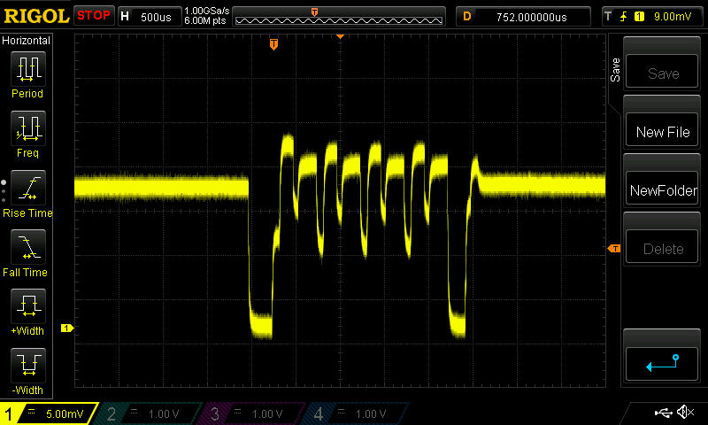
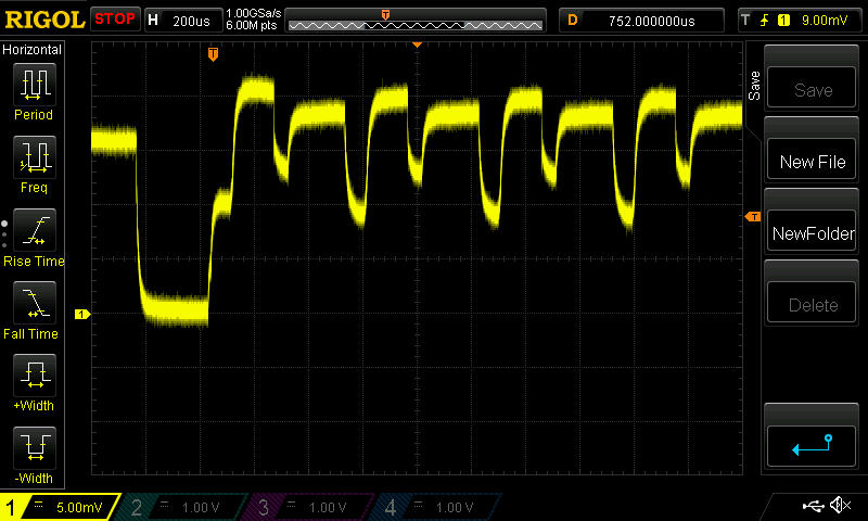
    It turns out my scope can do better than I thought. Here's the blob module again, but this time at 5mv/div.
    blob1x_1.jpg

    blob1x_2.jpg

    So, I may be able to use an even smaller resistor, because now I can go down to 1mv/div, whereas before it seemed it wouldn't let me go lower than 10mv/div. Hopefully that will help improve my measurement accuracy.


  • Mod

    @NeverDie shunt resistor & opamp. Not sure about the sampling speed of the AtMega yet. Have to dive into its data sheet first....


  • Mod

    @NeverDie transmission takes 233us in my measurements. What's the hdiv on your scope? 500/200us?


  • Hero Member

    @Yveaux said:

    @NeverDie transmission takes 233us in my measurements. What's the hdiv on your scope? 500/200us?

    Which chip? The 1242AF (presumed fake), or the one that might be genuine (the one on the Itead module)?


  • Mod

    @NeverDie any chip. Transmission time is identical every time.


  • Hero Member

    @Yveaux said:

    @NeverDie any chip. Transmission time if identical every time.

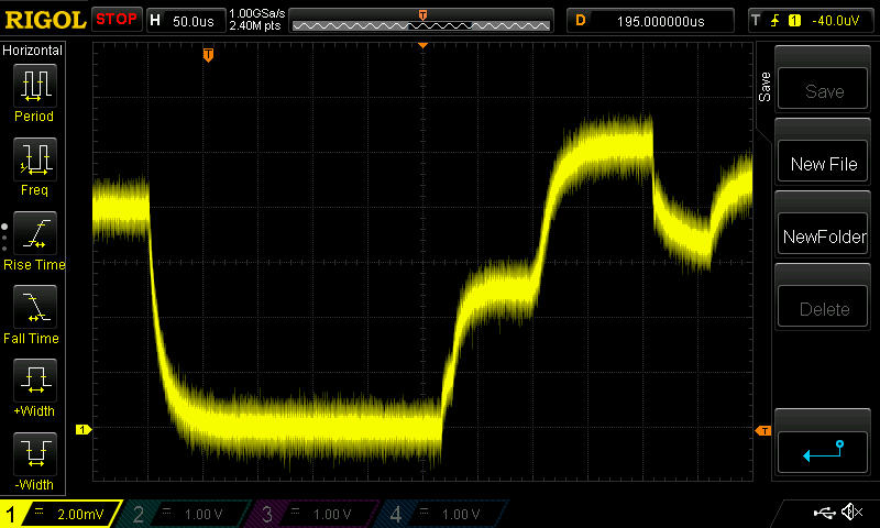
    Here's my best picture of the start of the transmission cycle for the blob module. I'm not sure where to call the actual start of it though, but we need to agree on that if we're going to compare numbers without pictures.

    blob_halfOhm.jpg
    It's labeled on the upper bar (just to the right of the red "STOP") 50us/div
    I modified the resister to be 1/2ohm, so now the vertical is 4ma/div, because it's 2mv/div vertical. Make sense?


  • Mod

    @NeverDie your horizontal scale is very different from what I measure.
    The initial low-level part in the last scope picture shows only part of what you identify as transmission time, while it already lasts roughy 250us. That's more than the whole transmission time I measure!
    We're definitely measuring differently.
    Quickly off my head: a single message is 14 bytes long (see the sniffer capture above). At 1mbit this will take 14*8/1mbit=112 us. Add some time for startup, preamble, shutdown etc. and I think total time will be in the order of 233us, as I measured.

    Could you try running the sketch I put on github to compare things? Probably you will only have to change cs/ss pins to run it (I stick to the default mysensors connections)
    It will also toggle a digital output on pin 3 before/after transmission which you can put on the scope together with the current measured, to have a reference when actual transmission takes place.

    Tonight (in 12 hours or so) I can do some more measurements if necessary.


  • Hero Member

    I just now noticed where you put your markers on your o-scope plot. There are two voltage increases, the second settles out higher than the first, and it looks like you're counting both. I would guess transmission doesn't really start until the higher voltage is reached, though, wouldn't you? That also is a better match to your 112us number. Perhaps the lower voltage corresponds to loading the buffer or something like that that doesn't need the higher transmit power.

    If you don't mind my asking, why the interest in the transmission length? Doesn't it have to be pretty similar from one type of chip to another, or else they won't interoperate?


  • Hero Member

    I think that's probably what's happening. I'm running on an 8Mhz Pro Mini (effectively), and you're running on a 16Mhz Uno. So, your first hump takes about half the time mine does ( is that right?), whereas both our second humps should take about the same amount of time. Ahhhhh..., except they don't. Your second hump appears to take longer than my blob module's second hump does. Mine is about 100us, and yours is about 150us? Is that what interests you?


  • Hero Member

    We would expect the data transmission per se to include a fixed prefix byte, 5 bytes of address, 9 bits of control, 4 bytes of payload, and 2 bytes of CRC (I think). 105 bits = 105uS. (I'm not sure where the 14 bytes in the calculation @Yveaux presented comes from. Either the nRF sends a 16 bit control but only documents 9 bits of it, or the nRF actually sends 9 bits but some software translates the 9th bit into a second byte for analysis purposes)

    Before that there's something like 130 uS to power up and stabilize. And there could be additional time gaps before or after the data per se.

    And of course before all that, there is the time to load the data and commands via SPI; power might potentially rise during that, I suppose.

    Only the time to load commands and data would seem to care whether the uC is running at 8 or 16 MHz. The 105 uS data time should be the same, if they are OTA compatible. The 130 uS power up and stabilizing time could vary between chip designs.

    Any way to see if the fake chip is one of those transmitting with more RF power output? (If it wastes more power doing the same job, not good. If it has the ability to run at higher power but can also be reduced to sip more carefully, that could be a win).

    I look forward to your further testing. Maybe worth checking how much supply current is saved in the other transmit power settings.


  • Hero Member

    @NeverDie said:

    It turns out my scope can do better than I thought. Here's the blob module again, but this time at 5mv/div.

    How did you reduce the noise so much in your later scope captures?


  • Hero Member

    @Zeph said:

    @NeverDie said:

    It turns out my scope can do better than I thought. Here's the blob module again, but this time at 5mv/div.

    How did you reduce the noise so much in your later scope captures?

    http://www.eevblog.com/forum/testgear/how-do-i-get-1mvdiv-on-the-1054z-i'm-only-getting-10mvdiv/
    Also,
    https://www.youtube.com/watch?v=DMXiD3dKYJc
    How's that for timely?


  • Hero Member

    Suggestion: for the clone/fake chips, could you test whether they have the SI24R01 power control?

    That is, set bit 1 of register 6 and see if they draw even more current. That should set the SI24R01 - or perhaps a derivative or clone of it - from 2-3 dBm to 7 dBm, which will probably mean using more supply current when the bit is 1 than when it's 0.

    See the (currently) last couple of links in the OP of the fakes thread.


  • Hero Member

    You might also see if the second register bank can be selected (ACTIVATE+0x53) and read. See http://sigrok.org/wiki/Protocol_decoder:Nrf24l01#Variants_and_clones_of_the_chip from the penultimate link on the fakes thread.

    If it has a second register bank then it's probably a BK24* series or a clone/derivative thereof. (Note that the contents of that second bank seem to be undocumented, at least in English). This niche is apparently popular enough that there are second level derivatives - for example advertised as being BK24* compatible which is in turn nRF24 compatible with extensions!

    I did catch a reference somewhere that implied there was a real RSSI in the second register bank in some derivative; that could be handy if true.


    There's a reference at that same link to the Nordic nRF24L01 (no plus) needing an ACTIVATE+0x73 command to enable certain features that are automatically available in the nRF24l01+.

    This is not something I am aware of. I wonder if some features like ESB can be enabled on the non-plus version? Anyway, if so, this might also be a test which helps sort out clones - if they look like a non-plus derivative, do they respond to ACTIVATE+0x73? (the linked source does not suggest that 250 Kbps mode is one of the features which could be activated)


  • Hero Member

    @Zeph: I'll may attempt those things tonight, though I'll be giving priority to moving over to TBRH20 first, as it will be better for comparisons if we minimize platform differences, as well as run the same library.


  • Hero Member

    @NeverDie said:

    @Zeph: I'll may attempt those things tonight, though I'll be giving priority to moving over to TBRH20 first, as it will be better for comparisons if we minimize platform differences, as well as run the same library.

    I agree that using the same library is good for cross comparison among multiple experimenters.

    However, if it turns out that the power profile differs between libraries, on the same hardware sending the same packet, that would be worth some investigation as well to understand why (and perhaps learn how to optimize power). Yeah, that's a different question than detecting variants and understanding their advantages/disadvantages, but the same measurement hardware can be used.


    I was wondering if a small cap across your sense resistor might smooth the traces a bit, and still tell us what we want to know - which is about average power, on a multi-microsecond timescale.


  • Using a non-scientific method; looking at the angle of battery discharge graphs over a week, I've noticed that the modules I got from ITEAD are draining batteries at about half the rate compared to an unknown (but probably fake) pretty good module.
    ITEAD module; slightly under 1% per day
    "other modules"; about 2% per day
    This is when measuring and transmitting DHT21 data every minute.


  • Hero Member

    @Zeph said:

    @NeverDie said:

    @Zeph: I'll may attempt those things tonight, though I'll be giving priority to moving over to TBRH20 first, as it will be better for comparisons if we minimize platform differences, as well as run the same library.

    I agree that using the same library is good for cross comparison among multiple experimenters.

    However, if it turns out that the power profile differs between libraries, on the same hardware sending the same packet, that would be worth some investigation as well to understand why (and perhaps learn how to optimize power). Yeah, that's a different question than detecting variants and understanding their advantages/disadvantages, but the same measurement hardware can be used.


    I was wondering if a small cap across your sense resistor might smooth the traces a bit, and still tell us what we want to know - which is about average power, on a multi-microsecond timescale.

    Sounds plausible. What cap value would you suggest? I pretty much skipped over learning analog electronics and haven't yet found the time to backfill that gap in my knowledge.

    I've been collecting on eevblog and elsewhere some seemingly good on-point advice about how to improve my scope captures in this situation. I'll probably learn one technique at a time, as time permits, and phase it in gradually.


  • Hero Member

    I don't really know what a good value would be. Since it's across a 1 ohm resistor (in one case), and you probably want an RC time in the vicinity of microseconds, I'd start with around 1 uF and move up or down from there based on the scope trace. You may be able to just clamp the (short) leads of a cap to your probes to get a look, before soldering.

    And I'll be interested in what other tips you collect that are useful.


  • Hero Member

    @Stric said:

    Using a non-scientific method; looking at the angle of battery discharge graphs over a week, I've noticed that the modules I got from ITEAD are draining batteries at about half the rate compared to an unknown (but probably fake) pretty good module.
    ITEAD module; slightly under 1% per day
    "other modules"; about 2% per day
    This is when measuring and transmitting DHT21 data every minute.

    Good information. Hopefully, the scope will help sort out whether that faster drain is mostly during transmit/receive activity, or mostly during the idle time, or both.


  • Hero Member

    @Zeph said:

    I don't really know what a good value would be. Since it's across a 1 ohm resistor (in one case), and you probably want an RC time in the vicinity of microseconds, I'd start with around 1 uF and move up or down from there based on the scope trace. You may be able to just clamp the (short) leads of a cap to your probes to get a look, before soldering.

    And I'll be interested in what other tips you collect that are useful.

    Sounds good. We'll solve for the cap value using empiricism. 😄

    Also, I want to start measuring sleep current soon, because it may prove decisive as to whether a module must be rejected from further consideration because of its potential impact on battery life. Stric's data suggests there are significant differences to be found there. I suspect saving power is one of the harder engineering challenges--or, if not, at least an area where clones may get sloppy--and it might serve as a good separator.


  • Hero Member

    Agreed. If the module takes more power during transmit because it's putting out more RF, we might be able to back it off by using less than the maximum power settings, or use it in applications where it more rarely transmits.

    But if it uses too much sleep current, it's a bad option for battery power.


  • Hero Member

    @Zeph said:

    Agreed. If the module takes more power during transmit because it's putting out more RF, we might be able to back it off by using less than the maximum power settings, or use it in applications where it more rarely transmits.

    But if it uses too much sleep current, it's a bad option for battery power.

    Exactly! You said it better than I did.


  • Hero Member

    @NeverDie It should be possible to get some better (noiseless) measurements on the rigol scope.... at least if I look at what HARI is measuring on the ESP8266 current...


  • Hero Member

    I hooked up the uCurrent inline with the Itead NRF24L01+ module, measured using a Fluke 87V multimeter, and I got these measurements:

    Powered Down (Sleep): 0.6uA
    Standby: 22.6uA

    I'm satisfied that these are within error tolerances for the expected results.

    Prior to that, I tested the blob module and seemed to get bizarre results. I'm going to go back and re-test now that I'm reasonably confident the test setup and measurements are working right.

    I'm using an Arduino Uno. This was the test code I used:

    /* Adapted by NeverDie on 8/11/2015 to facilitate uCurrent measurements.
    
    /*
     Copyright (C) 2011 J. Coliz <maniacbug@ymail.com>
    
     This program is free software; you can redistribute it and/or
     modify it under the terms of the GNU General Public License
     version 2 as published by the Free Software Foundation.
     
     TMRh20 2014 - Updates to the library allow sleeping both in TX and RX modes:
          TX Mode: The radio can be powered down (.9uA current) and the Arduino slept using the watchdog timer
          RX Mode: The radio can be left in standby mode (22uA current) and the Arduino slept using an interrupt pin
     */
    
    /**
     * Example RF Radio Ping Pair which Sleeps between Sends
     *
     * This is an example of how to use the RF24 class to create a battery-
     * efficient system.  It is just like the GettingStarted_CallResponse example, but the
     * ping node powers down the radio and sleeps the MCU after every
     * ping/pong cycle, and the receiver sleeps between payloads.
     *
     * Write this sketch to two different nodes,
     * connect the role_pin to ground on one.  The ping node sends the current
     * time to the pong node, which responds by sending the value back.  The ping
     * node can then see how long the whole cycle took.
     */
    
    #include <SPI.h>
    #include <avr/sleep.h>
    #include <avr/power.h>
    #include "nRF24L01.h"
    #include "RF24.h"
    #include "printf.h"
    
    
    // Set up nRF24L01 radio on SPI bus plus pins 7 & 8
    RF24 radio(7,8);
    
    // sets the role of this unit in hardware.  Connect to GND to be the 'pong' receiver
    // Leave open to be the 'ping' transmitter
    const int role_pin = 5;
    
    const uint64_t pipes[2] = { 0xF0F0F0F0E1LL, 0xF0F0F0F0D2LL };   // Radio pipe addresses for the 2 nodes to communicate.
    
    // Role management
    // Set up role.  This sketch uses the same software for all the nodes
    // in this system.  Doing so greatly simplifies testing.  The hardware itself specifies
    // which node it is.
    
    // The various roles supported by this sketch
    typedef enum { role_ping_out = 1, role_pong_back } role_e;
    
    // The debug-friendly names of those roles
    const char* role_friendly_name[] = { "invalid", "Ping out", "Pong back"};
    
    // The role of the current running sketch
    role_e role;
    
    void setup(){
    
      // set up the role pin
      pinMode(role_pin, INPUT);
      digitalWrite(role_pin,HIGH);
      delay(20); // Just to get a solid reading on the role pin
    
      // read the address pin, establish our role
      if ( digitalRead(role_pin) )
        role = role_ping_out;
      else
        role = role_pong_back;
    
      Serial.begin(57600);
      printf_begin();
      printf("\n\rRF24/examples/pingpair_sleepy/\n\r");
      printf("ROLE: %s\n\r",role_friendly_name[role]);
    
      radio.begin();
    
      // Open pipes to other nodes for communication
    
      // This simple sketch opens two pipes for these two nodes to communicate
      // back and forth.
      // Open 'our' pipe for writing
      // Open the 'other' pipe for reading, in position #1 (we can have up to 5 pipes open for reading)
    
      if ( role == role_ping_out ) {
        radio.openWritingPipe(pipes[0]);
        radio.openReadingPipe(1,pipes[1]);
      } else {
        radio.openWritingPipe(pipes[1]);
        radio.openReadingPipe(1,pipes[0]);
      }
    
      
      // Dump the configuration of the rf unit for debugging
      radio.printDetails();
    }
    
    void loop(){
    
      radio.powerDown();              // NOTE: The radio MUST be powered back up again manually
      delay(5000);
      radio.powerUp();                // Power up the radio after sleeping
      delay(5000);
     
    }


  • Hero Member

    Yup, same as before. The measurements on the blob module are:
    -43.3ua and -42.8ua.

    I'm not sure which is standby current and which is sleep current. I definitely was not expecting a negative current. There's not much difference in magnitude between the two currents.

    So, I tried it on a different blob module:
    -43.5ua and -42.9ua.
    Essentially the same results.

    Truly bizarre. What's going on? I'm powering the Uno through a roughly 9V battery pack of Eneloop batteries via its barrel jack, as with the earlier measurement of the Itead module, whose measurements not only met expected value, but they were positive currents, not negative ones.

    Here's the red module:
    Powered Down (Sleep): 1.6uA
    Standby: 13.9uA

    Here's an Addicore module from Amazon:
    Powered Down (Sleep): 1.8uA
    Standyby: 16.3uA

    It's a very simple test. I'd say anyone can do these measurements, provided they have a good way to measure microamps.


  • Hero Member

    @NeverDie said:

    -43.3ua and -42.8ua.

    So the blob module is so good that it is charging your batteries 😉


  • Hero Member

    @rvendrame said:

    @NeverDie said:

    -43.3ua and -42.8ua.

    So the blob module is so good that it is charging your batteries 😉

    I'm measuring the current between the Uno 3.3 Female header pin and the Vcc pin on the RF module.


  • Hero Member

    Now talking seriously, maybe the some current is leaking through the other pins (MISO, CE, CS, etc), from arduino to radio? That would could an negative VCC flow I think...


  • Hero Member

    It must be that. I wonder how it would measure if I were to use 3.3v on the datapins rather than the 5v the Uno uses.


  • Hero Member

    In theory it would require a logic level converter

    But for sure the atmega is tolerant between 3.3V and 5V. And probably the converter would introduce an error in the u-measurement, I guess.


  • Hero Member

    I plugged a blob module into the RFToy, which is effectively an 8Mhz Mini Pro running at 3.3v, and used a jig similar to the one before (just no resistor) to route the module Vcc current into the uCurrent.

    This time it is powered through the USB port, and the voltage is downshifted from there.

    New measurements for the blob module:
    Powered Down (Sleep): 3.3uA
    Standby: 67.2uA

    For comparison, I plugged the Itead module (Nordic tracecode 1301CL) into the same apparatus, and this time I got
    Powered Down (Sleep): 0.6uA
    Standby: 22.8uA
    which, within measurement error, I would call the same as when it was hooked up to the Uno.


  • Hero Member

    @Zeph: For the NRF24L01+ modules, I now have good enough current measurements that I wanted to get, so I'll be holding off on doing further measurements, at least for now. I want to try the RFM69HW for comparison, but that is outside the scope of this thread.


  • Hero Member

    BTW, using just my Fluke 87V multimeter set on the uA setting, the measurements I get are:

    Fluke 87V Itead Module Measurements:
    Powered Down(Sleep): 0.5uA
    Standby: 22.5uA

    and
    Fluke 87V Blob Module Meaasurements:
    Powwred Down(Sleep): 3.0uA
    Standby: 56uA

    and

    Fluke 87V Addicore module from Amazon Measurements:
    Powered Down: 1.2uA
    Standby: 18.2uA

    So, although a bit different than the uCurrent measurements, they seem good enough for separating out the fakes that I have from the genuine article (which at this point the evidence suggests is what the chip in the Itead module is).

    So, good news! Maybe all you need is a DMM with decent uA measurements. If I'd had this information at the very beginning of this thread, it would have saved me a lot of frustration and doubt. Now everyone can be empowered. 😄 The next time you buy modules, you can now easily test them right away and send them back if they're fake! 😄 😄 😄


  • Admin

    @NeverDie

    I told you in the fifth post 👊 😉


  • Hero Member

    @hek said:

    @NeverDie

    I told you in the fifth post 👊 😉

    Where exactly did you read it anyway?


  • Admin

    Just a lucky guess.


  • Hero Member

    @hek said:

    Just a lucky guess.

    What??? You were BS'ing me about reading it? 👊 😲

    @hek said:

    You should also compare the power consumption. From what I have read the genuine Nordic module has much better characteristics.


  • Admin

    @NeverDie said:

    You were BS'ing me then?

    Hmm.. no.. but I cannot for my mind recollect where I could have read it. So it might just have been a creation of my (weird) mind. 🙂


  • Hero Member

    All's well that ends well. 😄


  • Hero Member

    BTW, I just now measured this surface mount module using the uCurrent, and it measures out at

    Powered Down (Sleep): 0.7uA
    Standyby: 22.7uA

    smt.jpg

    Therefore, I deem it genuine. I got it at ICStation two or three months ago:
    http://www.icstation.com/nrf24l01-rfid-wireless-transmission-module-2dbm-p-4620.html

    It would help a lot if others here, when you measure your module, would post your measurements and where you got it from, and when. That way we can all benefit from the network effect and make better purchases and possibly avoid bad purchases also.


  • Hero Member

    Hmm.. no.. but I cannot for my mind recollect where I could have read it. So it might just have been a creation of my (weird) mind. 🙂

    Er, check the second sentence of the first (real) paragraph of the OP of the earlier fake nRF24L01+ thread.. Maybe that's where @hek got that impression.

    And now I am the one who doesn't recall exactly where I read that - but it's undoubtedly from one of the sources I linked to in that post, raised as one of the reasons to be concerned about fakes.


  • Hero Member

    Those with a low idle/sleep power usage are either Nordic or a quality clone.

    Even the blob modules would be workable in non-battery nodes, if they indeed have excellent range and low packet loss.

    So I just looked up the Fluke 87V, and the price is a bit high for my budget. So alas, the current state of our fake detection (pun acknowledged) is not a universal solution.

    Perhaps a variant with a coulomb counter will arise. Or perhaps using the 200x amplified differential ADC input of the Leonardo or Mega2560 with averaging.

    And I think it would be very apropos to distill the knowledge from these many posts into a wiki page. As with many threads here, there's some great info but sometimes it's embedded in hours of reading to find it again.


  • Hero Member

    @NeverDie - now that you have the measurement down, how about measuring receive current, and perhaps carrier-only transmit current? Both of those can be steady state.

    I'd still like to know how the various models rate in those areas too, while you have the setup handy.


  • Hero Member

    @Zeph said:

    ...carrier-only transmit current?

    What is "carrier only transmit current", and how would I measure that?


  • Hero Member

    Register 6 (RF_SETUP) bit 7 (CONT_WAVE) on p 55 of the rev 1 datasheet.

    Set it up to transmit constantly (carrier only, no data) and measure the Vcc current usage. (For a short time obviously!) Probably close to the current it would take while sending data.

    Likewise, measure current while waiting to receive with no actual data coming in (unless that's what your standby is).

    I haven't tried the constant-wave transmit mode, I just remembered that it was mentioned in the datasheet.


  • Hero Member

    For the IcStation module I profiled directly above, the receive current (using the microcurrent) measures out at 8.4mA using this sketch to put the module into receive mode:

    /* Adapted by NeverDie on 8/11/2015 for uCurrent measurements.
     *  Sketch for measuring receive current.
     */
    
    /*
     Copyright (C) 2011 J. Coliz <maniacbug@ymail.com>
    
     This program is free software; you can redistribute it and/or
     modify it under the terms of the GNU General Public License
     version 2 as published by the Free Software Foundation.
     
     TMRh20 2014 - Updates to the library allow sleeping both in TX and RX modes:
          TX Mode: The radio can be powered down (.9uA current) and the Arduino slept using the watchdog timer
          RX Mode: The radio can be left in standby mode (22uA current) and the Arduino slept using an interrupt pin
     */
    
    /**
     * Example RF Radio Ping Pair which Sleeps between Sends
     *
     * This is an example of how to use the RF24 class to create a battery-
     * efficient system.  It is just like the GettingStarted_CallResponse example, but the
     * ping node powers down the radio and sleeps the MCU after every
     * ping/pong cycle, and the receiver sleeps between payloads.
     *
     * Write this sketch to two different nodes,
     * connect the role_pin to ground on one.  The ping node sends the current
     * time to the pong node, which responds by sending the value back.  The ping
     * node can then see how long the whole cycle took.
     */
    
    #include <SPI.h>
    #include <avr/sleep.h>
    #include <avr/power.h>
    #include "nRF24L01.h"
    #include "RF24.h"
    #include "printf.h"
    
    
    // Set up nRF24L01 radio on SPI bus plus pins 7 & 8
    RF24 radio(7,8);
    
    // sets the role of this unit in hardware.  Connect to GND to be the 'pong' receiver
    // Leave open to be the 'ping' transmitter
    const int role_pin = 5;
    
    const uint64_t pipes[2] = { 0xF0F0F0F0E1LL, 0xF0F0F0F0D2LL };   // Radio pipe addresses for the 2 nodes to communicate.
    
    // Role management
    // Set up role.  This sketch uses the same software for all the nodes
    // in this system.  Doing so greatly simplifies testing.  The hardware itself specifies
    // which node it is.
    
    // The various roles supported by this sketch
    typedef enum { role_ping_out = 1, role_pong_back } role_e;
    
    // The debug-friendly names of those roles
    const char* role_friendly_name[] = { "invalid", "Ping out", "Pong back"};
    
    // The role of the current running sketch
    role_e role;
    
    void setup(){
    
      // set up the role pin
      pinMode(role_pin, INPUT);
      digitalWrite(role_pin,HIGH);
      delay(20); // Just to get a solid reading on the role pin
    
      // read the address pin, establish our role
      if ( digitalRead(role_pin) )
        role = role_ping_out;
      else
        role = role_pong_back;
    
      Serial.begin(57600);
      while (!Serial) {
        ; // wait for serial port to connect. Needed for Leonardo only
      }
      printf_begin();
      printf("\n\rRF24/examples/pingpair_sleepy/\n\r");
      printf("ROLE: %s\n\r",role_friendly_name[role]);
    
      radio.begin();
    
      // Open pipes to other nodes for communication
    
      // This simple sketch opens two pipes for these two nodes to communicate
      // back and forth.
      // Open 'our' pipe for writing
      // Open the 'other' pipe for reading, in position #1 (we can have up to 5 pipes open for reading)
    
      if ( role == role_ping_out ) {
        radio.openWritingPipe(pipes[0]);
        radio.openReadingPipe(1,pipes[1]);
      } else {
        radio.openWritingPipe(pipes[1]);
        radio.openReadingPipe(1,pipes[0]);
      }
    
      
      // Dump the configuration of the rf unit for debugging
      radio.printDetails();
    }
    
    void loop(){
    
      radio.startListening();
     
    }


    I can't promise to do the other measurements, as I'm facing some deadlines I need to attend to. If anyone else would like to pick up the baton and carry it forward, please feel free.


  • Hero Member

    I understand about other deadlines - I appreciate the efforts you have made so far.

    Sounds like all that's needed in the final version of your testing is a bent-pin 2x8 connector test shim such as you have described and photographed, and a $400 DVM 🙂


  • Hero Member

    @Zeph said:

    Sounds like all that's needed in the final version of your testing is a bent-pin 2x8 connector test shim such as you have described and photographed,

    Yes, a 2x4 connector, or I actually used (2) 1x6 female headers (I didn't have 1x4 female headers readily at hand)

    and a $400 DVM 🙂

    I imagine some of the cheaper DVM's would get the job done too. That's another topic entirely though.

    I'm not sure where you draw the line on how much testing is enough. I think it probably already is enough. 80/20 rule. ☺


  • Hero Member

    Have you decided to toss the blob modules (or put them in the back of the drawers), in favor of genuine Nordic only?


  • Hero Member

    @Zeph said:

    Have you decided to toss the blob modules (or put them in the back of the drawers), in favor of genuine Nordic only?

    No, at present I still prefer the blob modules. It may yet turn out that there's a better PCB or antenna or something for the genuine chips that will make a huge difference in their effective performance, but so far I'm underwhelmed by the modules with genuine chips. Also, modules with the genuine chips seem to cost around ~$3/each, and so for about only an extra dollar I could have an RFM69HW. Yesterday I ordered a couple Moteino's with the RFM69HW, and so after they arrive I'll see how that goes rather than re-invent the wheel. They were kinda pricey, which is my main reservation about them.

    If others are happy with their genuine chip NRF24L01+ modules, then good for them. Unfortunately I can't count myself among them, and so I'm restless to find something and settle on it. My guess is it may be the blob module, or it may be the RFM69.


  • Hero Member

    Ah, OK.

    I saw the testing as serving two purposes:

    • Learning a "power signature" to distinguish variations on the chips
    • Finding out how bad (or good) the variants are in regard to power usage

    Seems like the first is nailed. The latter has begun to be characterized (thanks to you). The idle and sleep power is substantially greater on the blobs (for example). If the 8.4 ma for Receive is for the blobs, that doesn't sound bad, don't know about transmit.

    And if powered by the mains, it doesn't much matter.


  • Hero Member

    @Zeph said:

    ....don't know about transmit.

    Blob module transmit current was about 20ma, (my interpretation of the oscilliscope pictures I posted). I was surprised that the "listening" current was just 8.4ma, because that's lower than the spec sheet for "receiving" current. I don't know, but perhaps "receiving" consumes more current than just "listening."

    On a relative scale compared to the other modules, the blob modules obviously consume more current. However, on an absolute scale, they seem like they may be good enough..

    And if powered by the mains, it doesn't much matter.


  • Hero Member

    @Zeph Looks as though you could use the LTC2440 to measure the sleep and standby currents and read the results with your arduino: http://dangerousprototypes.com/forum/viewtopic.php?f=2&t=4247#p45583

    or maybe use one of these breakout boards to similar effect:
    http://www.ebay.com/itm/LTC2400-24bit-analog-to-digital-converter-ADC-module-temp-sensor-SPI-AVR-arduino-/111005456125?pt=LH_DefaultDomain_0&hash=item19d870d6fd


  • Hardware Contributor

    I'm seeing similar results with my radios. I bought these from aliexpress and then after reading the various threads about fakes and the problems people were having, I bought a bunch of authentic modules from ITEAD just to avoid those headaches. The real modules have much cleaner PCB's and better looking solder joints. The two types seem to be able to talk to each other OK but if set two modules at opposite ends of the house (with 2 exterior walls in between as well), the cheap modules still connect and the genuine ones don't. I'm assuming this is similar to what you're seeing with the real modules having a lower transmit power. I'm now regretting spending the extra money on the genuine modules (if anyone in the CONUS wants some genuine modules, PM me and I'll sell you some at my cost).


  • Hero Member

    Thank you! Finally some confirmation of what I've been saying.

    I received some "genuine" modules from AliExpress today: http://www.aliexpress.com/item/Free-shipping-Original-Genuine-NRF24L01-Wireless-Module-2-4G-wireless-communication-module-2-54mm-Interface-2/1781618813.html

    Power Down (Sleep): 0.5uA
    Standby: 23.5uA
    Listening: 8.6ma
    The transmit waveform looks exactly the same as the the module from Itead.

    Therefore, I deem them genuine.


  • Hero Member

    I was able to sharpen my o-scope pictures by turning on Hi-Res mode. With this better detail, a lot more is apparently different between the genuine modules and the blob modules.

    Here are some transmit shots of the new genuine modules:

    genuin1.jpg

    genuine2.jpg

    and here are some shots of the blob module, also now taken at Hi-Res on the o-scope:

    blob1.jpg
    blob2.jpg
    blob3.jpg

    As you can see now that I'm using Hi-Res mode, even the shapes of the waveforms are completely different looking.

    Reminder: because I'm now using a 1/2 ohm sense resister, each verticle devision now represents 4ma.
    So, eyeballing it, the genuine chips are using about 12ma for their transmit current, whereas the blob module chips are closer to about 18ma.

    Also, the second peak after the first peak is higher on the genuine chips, whereas it is lower on the blob chips. I don't know what those peaks represent.


Log in to reply
 

Suggested Topics

  • 87
  • 7
  • 7
  • 2
  • 6
  • 5

14
Online

11.4k
Users

11.1k
Topics

112.7k
Posts