Which are the *best* NRF24L01+ modules?
-
-
It turns out my scope can do better than I thought. Here's the blob module again, but this time at 5mv/div.
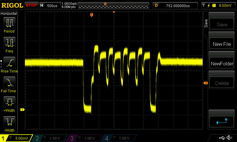
So, I may be able to use an even smaller resistor, because now I can go down to 1mv/div, whereas before it seemed it wouldn't let me go lower than 10mv/div. Hopefully that will help improve my measurement accuracy.
-
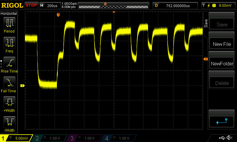
@NeverDie transmission takes 233us in my measurements. What's the hdiv on your scope? 500/200us?
-
-
@Yveaux said:
@NeverDie any chip. Transmission time if identical every time.
Here's my best picture of the start of the transmission cycle for the blob module. I'm not sure where to call the actual start of it though, but we need to agree on that if we're going to compare numbers without pictures.
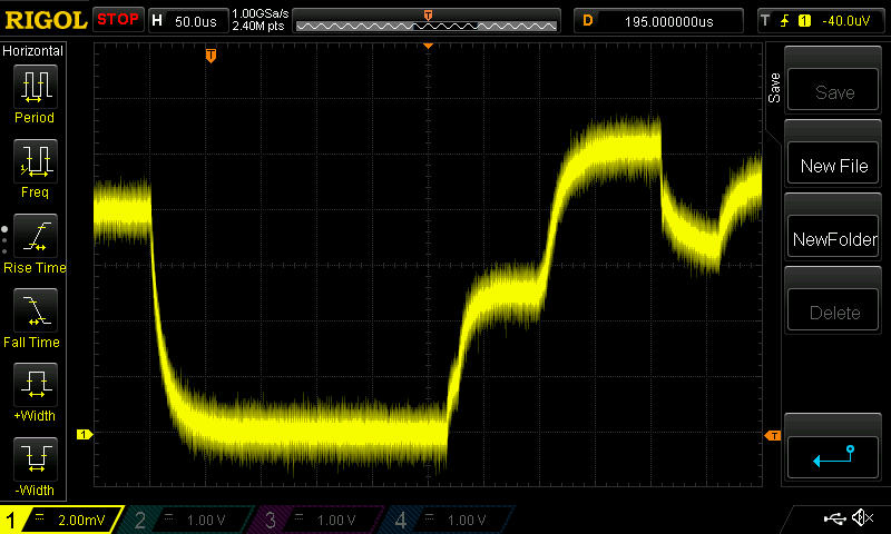
It's labeled on the upper bar (just to the right of the red "STOP") 50us/div
I modified the resister to be 1/2ohm, so now the vertical is 4ma/div, because it's 2mv/div vertical. Make sense? -
@Yveaux said:
@NeverDie any chip. Transmission time if identical every time.
Here's my best picture of the start of the transmission cycle for the blob module. I'm not sure where to call the actual start of it though, but we need to agree on that if we're going to compare numbers without pictures.
It's labeled on the upper bar (just to the right of the red "STOP") 50us/div
I modified the resister to be 1/2ohm, so now the vertical is 4ma/div, because it's 2mv/div vertical. Make sense?@NeverDie your horizontal scale is very different from what I measure.
The initial low-level part in the last scope picture shows only part of what you identify as transmission time, while it already lasts roughy 250us. That's more than the whole transmission time I measure!
We're definitely measuring differently.
Quickly off my head: a single message is 14 bytes long (see the sniffer capture above). At 1mbit this will take 14*8/1mbit=112 us. Add some time for startup, preamble, shutdown etc. and I think total time will be in the order of 233us, as I measured.Could you try running the sketch I put on github to compare things? Probably you will only have to change cs/ss pins to run it (I stick to the default mysensors connections)
It will also toggle a digital output on pin 3 before/after transmission which you can put on the scope together with the current measured, to have a reference when actual transmission takes place.Tonight (in 12 hours or so) I can do some more measurements if necessary.
-
I just now noticed where you put your markers on your o-scope plot. There are two voltage increases, the second settles out higher than the first, and it looks like you're counting both. I would guess transmission doesn't really start until the higher voltage is reached, though, wouldn't you? That also is a better match to your 112us number. Perhaps the lower voltage corresponds to loading the buffer or something like that that doesn't need the higher transmit power.
If you don't mind my asking, why the interest in the transmission length? Doesn't it have to be pretty similar from one type of chip to another, or else they won't interoperate?
-
I think that's probably what's happening. I'm running on an 8Mhz Pro Mini (effectively), and you're running on a 16Mhz Uno. So, your first hump takes about half the time mine does ( is that right?), whereas both our second humps should take about the same amount of time. Ahhhhh..., except they don't. Your second hump appears to take longer than my blob module's second hump does. Mine is about 100us, and yours is about 150us? Is that what interests you?
-
We would expect the data transmission per se to include a fixed prefix byte, 5 bytes of address, 9 bits of control, 4 bytes of payload, and 2 bytes of CRC (I think). 105 bits = 105uS. (I'm not sure where the 14 bytes in the calculation @Yveaux presented comes from. Either the nRF sends a 16 bit control but only documents 9 bits of it, or the nRF actually sends 9 bits but some software translates the 9th bit into a second byte for analysis purposes)
Before that there's something like 130 uS to power up and stabilize. And there could be additional time gaps before or after the data per se.
And of course before all that, there is the time to load the data and commands via SPI; power might potentially rise during that, I suppose.
Only the time to load commands and data would seem to care whether the uC is running at 8 or 16 MHz. The 105 uS data time should be the same, if they are OTA compatible. The 130 uS power up and stabilizing time could vary between chip designs.
Any way to see if the fake chip is one of those transmitting with more RF power output? (If it wastes more power doing the same job, not good. If it has the ability to run at higher power but can also be reduced to sip more carefully, that could be a win).
I look forward to your further testing. Maybe worth checking how much supply current is saved in the other transmit power settings.
-
It turns out my scope can do better than I thought. Here's the blob module again, but this time at 5mv/div.
So, I may be able to use an even smaller resistor, because now I can go down to 1mv/div, whereas before it seemed it wouldn't let me go lower than 10mv/div. Hopefully that will help improve my measurement accuracy.
-
@NeverDie said:
It turns out my scope can do better than I thought. Here's the blob module again, but this time at 5mv/div.
How did you reduce the noise so much in your later scope captures?
@Zeph said:
@NeverDie said:
It turns out my scope can do better than I thought. Here's the blob module again, but this time at 5mv/div.
How did you reduce the noise so much in your later scope captures?
http://www.eevblog.com/forum/testgear/how-do-i-get-1mvdiv-on-the-1054z-i'm-only-getting-10mvdiv/
Also,
https://www.youtube.com/watch?v=DMXiD3dKYJc
How's that for timely? -
Suggestion: for the clone/fake chips, could you test whether they have the SI24R01 power control?
That is, set bit 1 of register 6 and see if they draw even more current. That should set the SI24R01 - or perhaps a derivative or clone of it - from 2-3 dBm to 7 dBm, which will probably mean using more supply current when the bit is 1 than when it's 0.
See the (currently) last couple of links in the OP of the fakes thread.
-
You might also see if the second register bank can be selected (ACTIVATE+0x53) and read. See http://sigrok.org/wiki/Protocol_decoder:Nrf24l01#Variants_and_clones_of_the_chip from the penultimate link on the fakes thread.
If it has a second register bank then it's probably a BK24* series or a clone/derivative thereof. (Note that the contents of that second bank seem to be undocumented, at least in English). This niche is apparently popular enough that there are second level derivatives - for example advertised as being BK24* compatible which is in turn nRF24 compatible with extensions!
I did catch a reference somewhere that implied there was a real RSSI in the second register bank in some derivative; that could be handy if true.
There's a reference at that same link to the Nordic nRF24L01 (no plus) needing an ACTIVATE+0x73 command to enable certain features that are automatically available in the nRF24l01+.
This is not something I am aware of. I wonder if some features like ESB can be enabled on the non-plus version? Anyway, if so, this might also be a test which helps sort out clones - if they look like a non-plus derivative, do they respond to ACTIVATE+0x73? (the linked source does not suggest that 250 Kbps mode is one of the features which could be activated)
-
@Zeph: I'll may attempt those things tonight, though I'll be giving priority to moving over to TBRH20 first, as it will be better for comparisons if we minimize platform differences, as well as run the same library.
@NeverDie said:
@Zeph: I'll may attempt those things tonight, though I'll be giving priority to moving over to TBRH20 first, as it will be better for comparisons if we minimize platform differences, as well as run the same library.
I agree that using the same library is good for cross comparison among multiple experimenters.
However, if it turns out that the power profile differs between libraries, on the same hardware sending the same packet, that would be worth some investigation as well to understand why (and perhaps learn how to optimize power). Yeah, that's a different question than detecting variants and understanding their advantages/disadvantages, but the same measurement hardware can be used.
I was wondering if a small cap across your sense resistor might smooth the traces a bit, and still tell us what we want to know - which is about average power, on a multi-microsecond timescale.
-
Using a non-scientific method; looking at the angle of battery discharge graphs over a week, I've noticed that the modules I got from ITEAD are draining batteries at about half the rate compared to an unknown (but probably fake) pretty good module.
ITEAD module; slightly under 1% per day
"other modules"; about 2% per day
This is when measuring and transmitting DHT21 data every minute. -
@NeverDie said:
@Zeph: I'll may attempt those things tonight, though I'll be giving priority to moving over to TBRH20 first, as it will be better for comparisons if we minimize platform differences, as well as run the same library.
I agree that using the same library is good for cross comparison among multiple experimenters.
However, if it turns out that the power profile differs between libraries, on the same hardware sending the same packet, that would be worth some investigation as well to understand why (and perhaps learn how to optimize power). Yeah, that's a different question than detecting variants and understanding their advantages/disadvantages, but the same measurement hardware can be used.
I was wondering if a small cap across your sense resistor might smooth the traces a bit, and still tell us what we want to know - which is about average power, on a multi-microsecond timescale.
@Zeph said:
@NeverDie said:
@Zeph: I'll may attempt those things tonight, though I'll be giving priority to moving over to TBRH20 first, as it will be better for comparisons if we minimize platform differences, as well as run the same library.
I agree that using the same library is good for cross comparison among multiple experimenters.
However, if it turns out that the power profile differs between libraries, on the same hardware sending the same packet, that would be worth some investigation as well to understand why (and perhaps learn how to optimize power). Yeah, that's a different question than detecting variants and understanding their advantages/disadvantages, but the same measurement hardware can be used.
I was wondering if a small cap across your sense resistor might smooth the traces a bit, and still tell us what we want to know - which is about average power, on a multi-microsecond timescale.
Sounds plausible. What cap value would you suggest? I pretty much skipped over learning analog electronics and haven't yet found the time to backfill that gap in my knowledge.
I've been collecting on eevblog and elsewhere some seemingly good on-point advice about how to improve my scope captures in this situation. I'll probably learn one technique at a time, as time permits, and phase it in gradually.
-
I don't really know what a good value would be. Since it's across a 1 ohm resistor (in one case), and you probably want an RC time in the vicinity of microseconds, I'd start with around 1 uF and move up or down from there based on the scope trace. You may be able to just clamp the (short) leads of a cap to your probes to get a look, before soldering.
And I'll be interested in what other tips you collect that are useful.
-
Using a non-scientific method; looking at the angle of battery discharge graphs over a week, I've noticed that the modules I got from ITEAD are draining batteries at about half the rate compared to an unknown (but probably fake) pretty good module.
ITEAD module; slightly under 1% per day
"other modules"; about 2% per day
This is when measuring and transmitting DHT21 data every minute.@Stric said:
Using a non-scientific method; looking at the angle of battery discharge graphs over a week, I've noticed that the modules I got from ITEAD are draining batteries at about half the rate compared to an unknown (but probably fake) pretty good module.
ITEAD module; slightly under 1% per day
"other modules"; about 2% per day
This is when measuring and transmitting DHT21 data every minute.Good information. Hopefully, the scope will help sort out whether that faster drain is mostly during transmit/receive activity, or mostly during the idle time, or both.
-
I don't really know what a good value would be. Since it's across a 1 ohm resistor (in one case), and you probably want an RC time in the vicinity of microseconds, I'd start with around 1 uF and move up or down from there based on the scope trace. You may be able to just clamp the (short) leads of a cap to your probes to get a look, before soldering.
And I'll be interested in what other tips you collect that are useful.
@Zeph said:
I don't really know what a good value would be. Since it's across a 1 ohm resistor (in one case), and you probably want an RC time in the vicinity of microseconds, I'd start with around 1 uF and move up or down from there based on the scope trace. You may be able to just clamp the (short) leads of a cap to your probes to get a look, before soldering.
And I'll be interested in what other tips you collect that are useful.
Sounds good. We'll solve for the cap value using empiricism. :smile:
Also, I want to start measuring sleep current soon, because it may prove decisive as to whether a module must be rejected from further consideration because of its potential impact on battery life. Stric's data suggests there are significant differences to be found there. I suspect saving power is one of the harder engineering challenges--or, if not, at least an area where clones may get sloppy--and it might serve as a good separator.