Skip to content
  • OpenHardware.io
  • Categories
  • Recent
  • Tags
  • Popular
Skins
  • Light
  • Brite
  • Cerulean
  • Cosmo
  • Flatly
  • Journal
  • Litera
  • Lumen
  • Lux
  • Materia
  • Minty
  • Morph
  • Pulse
  • Sandstone
  • Simplex
  • Sketchy
  • Spacelab
  • United
  • Yeti
  • Zephyr
  • Dark
  • Cyborg
  • Darkly
  • Quartz
  • Slate
  • Solar
  • Superhero
  • Vapor

  • Default (No Skin)
  • No Skin
Collapse
Brand Logo
  1. Home
  2. Hardware
  3. MySensors shield and RGBW Controller
  • Getting Started
  • Controller
  • Build
  • Hardware
  • Download/API
  • Forum
  • Store

MySensors shield and RGBW Controller

Scheduled Pinned Locked Moved Hardware
66 Posts 16 Posters 32.1k Views 21 Watching
  • Oldest to Newest
  • Newest to Oldest
  • Most Votes
Reply
  • Reply as topic
Log in to reply
This topic has been deleted. Only users with topic management privileges can see it.
  • L Offline
    L Offline
    LastSamurai
    Hardware Contributor
    wrote on last edited by
    #5

    I thought thats what I did, but perhaps I misclicked ;) I thought the hardware part would be right.

    1 Reply Last reply
    0
    • K Offline
      K Offline
      kalle
      wrote on last edited by kalle
      #6

      How many LEDs do you want drive with this controller, because the MOSFET has a limit of 4.6A.
      A full bright white LED (like a SMD5050) can have ~60mA current - so you can drive save 70 LEDs on a strip with this controller.

      But anyway, nice design :-)

      P 1 Reply Last reply
      0
      • L Offline
        L Offline
        LastSamurai
        Hardware Contributor
        wrote on last edited by
        #7

        @hek Have you already moved it? I still see it in the homeseer section.

        @kalle Thanks for the hint. It should be enough in most cases for me, but better safe than sorry. Can you recommend a mosfet in SOT-23 package with a higher limit?

        1 Reply Last reply
        0
        • K Offline
          K Offline
          kalle
          wrote on last edited by
          #8

          Sorry, I didn't find a sot-23 Mosfet with a higher limit, but maybe you have enough space to use TO-220. There are a lot of Mosefet's with a higher limit available - like this one.

          http://www.conrad.de/ce/de/product/162869/MOSFET-International-Rectifier-IRLZ24NPBF-HEXFET-Gehaeuseart-TO-220-ID-18-A-UDS-55-V?ref=searchDetail

          1 Reply Last reply
          0
          • L Offline
            L Offline
            LastSamurai
            Hardware Contributor
            wrote on last edited by
            #9

            Thanks for the feedback! I will try to add some bigger MOSFETs. Perhaps I can add both and make it optional. For now I finalised my shield. I moved the headers for the sensor, so that they are spaced like the arduino pro pins (distance). Also redid the routing and some other small parts. I just ordered them from dirtypcbs. Once I get them and they work I will add a link here if anybody else wants some.
            I guess next I will work on the rgbw shield again.

            1 Reply Last reply
            0
            • L Offline
              L Offline
              LastSamurai
              Hardware Contributor
              wrote on last edited by
              #10

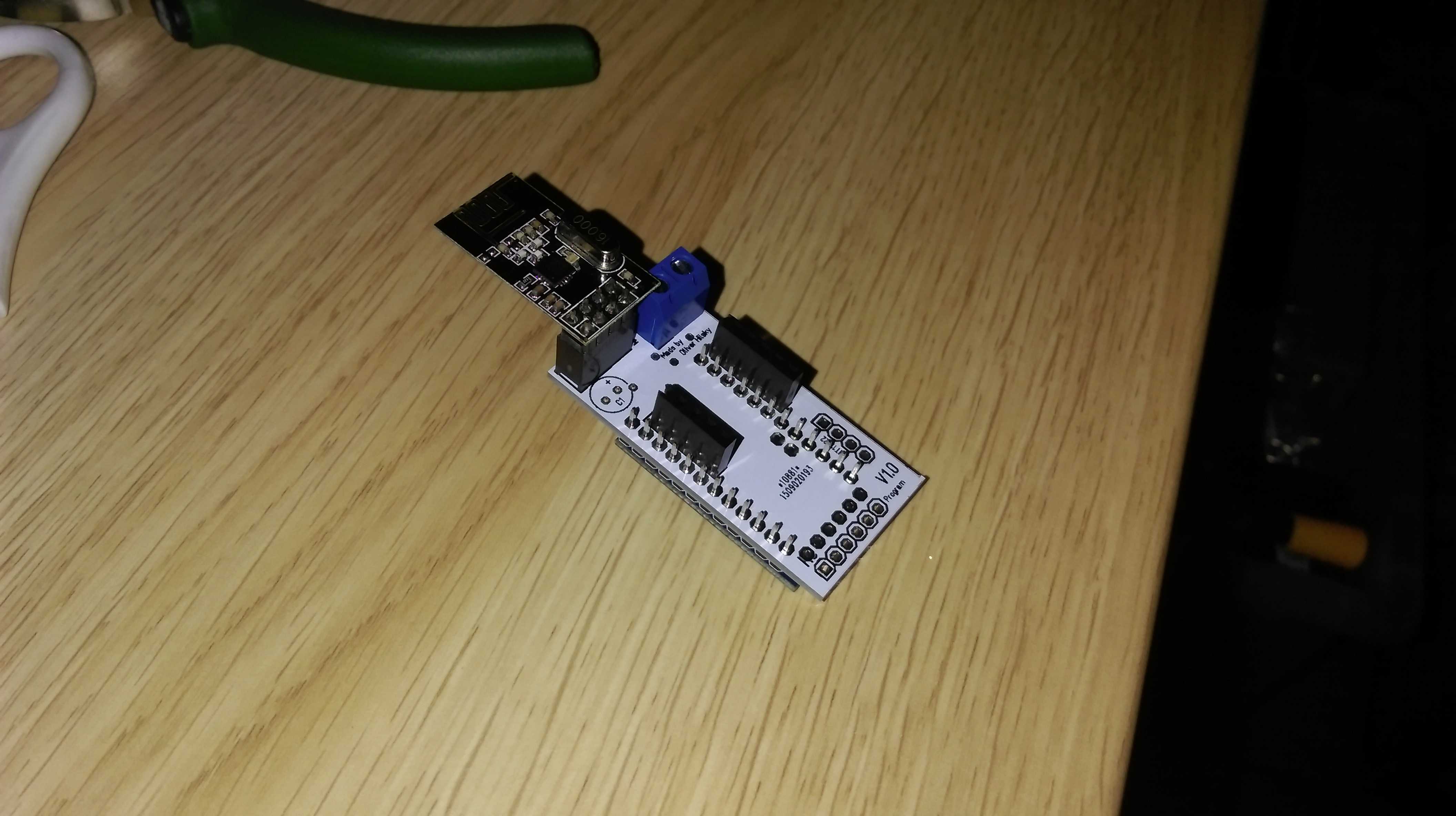
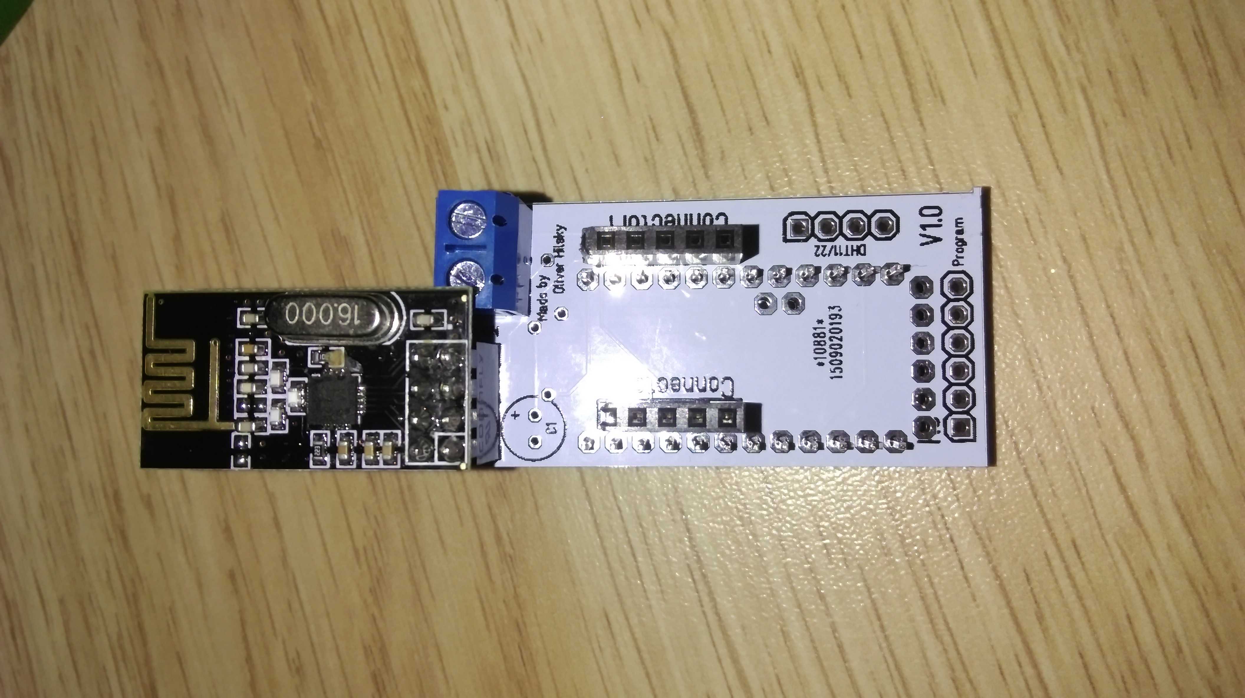
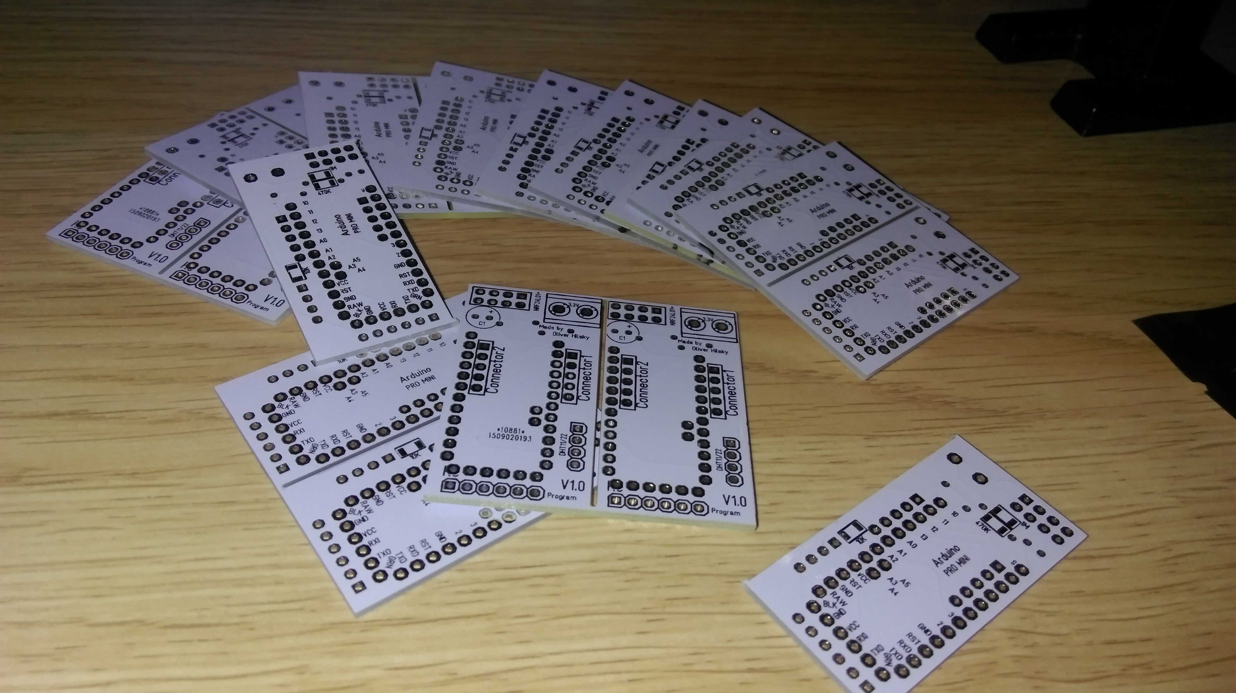
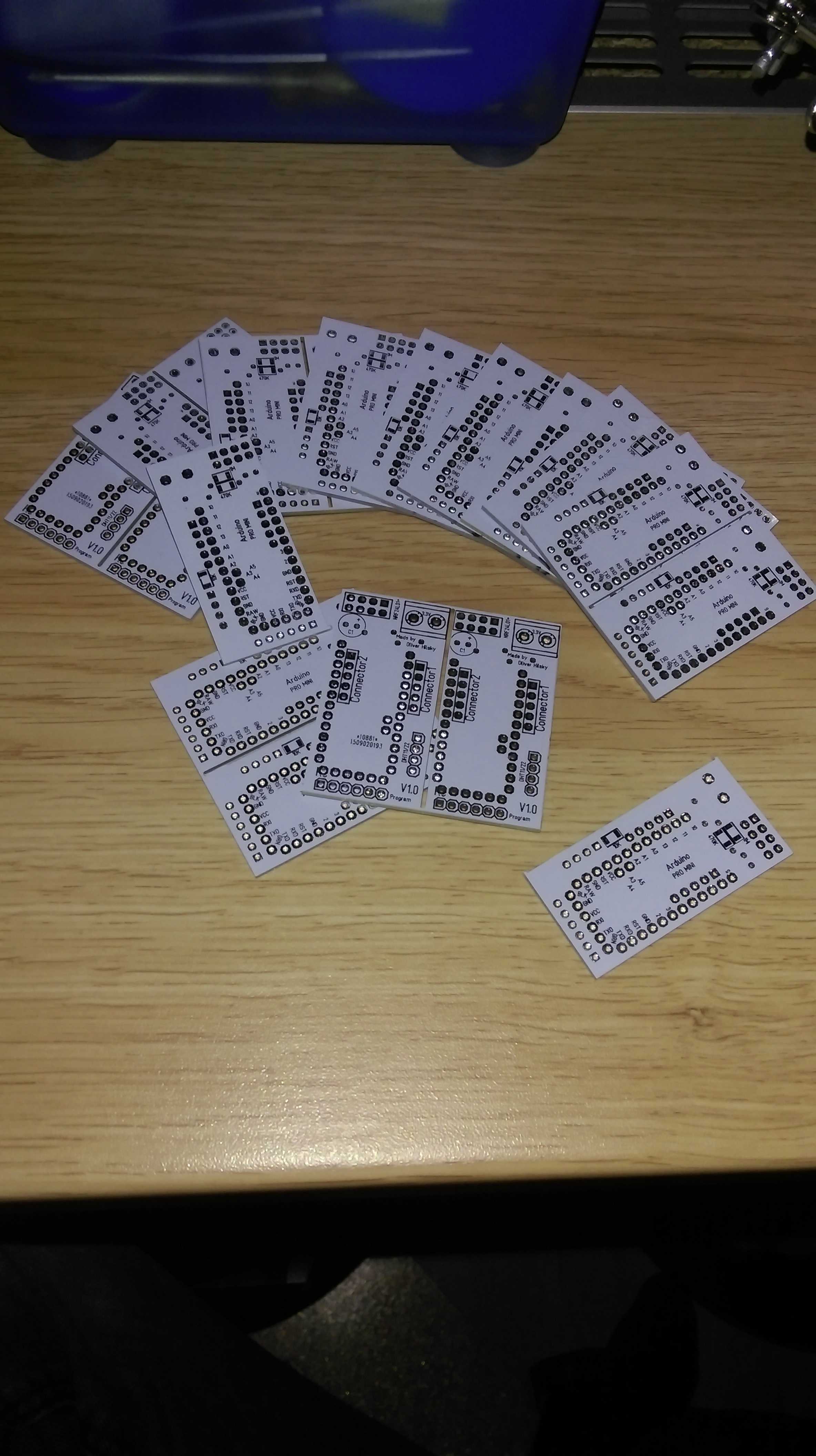
              Yeah :sparkles: my PCBs from dirtypcbs finally arrived! So I instantly had to open the package and I must say: these pcbs are really well made (for that price). Here are pics. As you can see I designed them so that 2 fit on one 5x5cm pcb. So I have gotten myself 24 potential "smart" sensors now :smiley:
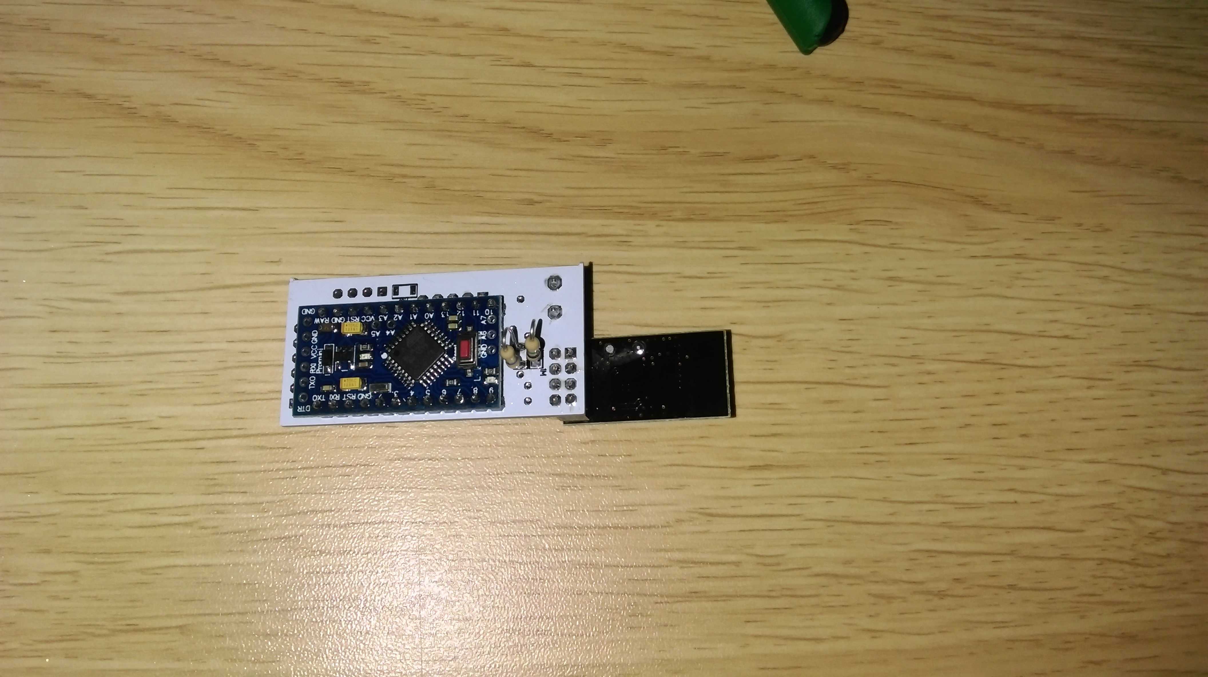
              I haven't gotten all components yet for multiple sensors but I started with one test sensor anyways. It has through hole resistors instead of some smd ones, no capacitor and no DHT22 yet. But once I get the components I will add them on the prototype. For now it's up and running with a demo sketch that just sends random values.
              And everything seems to be working nicely. Yeah^^

              Next step is to finalize the components and test some other components as arduino shield like components on the two pin headers I added for that one. And I already found some small things that I could still improve.

              Once that's all done I will finalize the RGBW ones and send them of for production.

              Love to hear your feedback and tipps guys!

              PS can I somehow add these pictures as thumbnails? They are quite big...
              IMAG0013.jpg IMAG0012.jpg IMAG0010.jpg IMAG0009.jpg IMAG0008.jpg

              1 Reply Last reply
              2
              • L Offline
                L Offline
                LastSamurai
                Hardware Contributor
                wrote on last edited by
                #11

                My test sensorboard has been successfully running for over a week now :sparkles:
                It's only reporting fake values because my new sensors (DHT22) did not yet arrive but this looks good already.

                This night there was an "accident" though. Suddenly the sensor stoped sending data. When I took it from its "hiding"spot I saw that the second LED on the board was constantly on. Do you guys knwo what that is for?
                When I connected my serial to usb adapter to check the node's status the sensor powered up again and is since working perfectly again. The adapter does also power the board though. The battery levels are still reported as 3.4V so this should not be a problem. Any idea what the problem could be?
                I haven't added the capacitor yet... might that be the problem?

                1 Reply Last reply
                0
                • L Offline
                  L Offline
                  LastSamurai
                  Hardware Contributor
                  wrote on last edited by
                  #12

                  Ok, the same thing just happened again. Before the unit shut down it did restart about 3 times (thats whats in the log from my domoticz). Might this be the brownout shutdown? Voltage with external multimeter is at aboud 2.7-2.8V. So do I have to change my fuse settings? Or perhaps use the mysensor bootloader...
                  I also realized that I did connect my batteries directly to the VCC pins, not the raw pin. This means that the voltage converter on the board isn't used (right?). Should I change that, or what's happening with the 3.3V converter if it gets input voltages lower than 3V?

                  I also realise that my usb to serial converter might be running at 5V so I might have killed my NRF (and possibly the arduino too) :disappointed:

                  How do you guys handle this?

                  1 Reply Last reply
                  0
                  • A Offline
                    A Offline
                    activemind
                    wrote on last edited by
                    #13

                    Is it available for other people yet? I am very interested in LED strip drivers connected to mySensor network and your PCB seems to fit the bill nicely.

                    Good job.

                    -AM

                    1 Reply Last reply
                    0
                    • L Offline
                      L Offline
                      LastSamurai
                      Hardware Contributor
                      wrote on last edited by LastSamurai
                      #14

                      Not yet, although the designs are above. I have to work out the errors in my normal pcb yet. Then I can easily switch over to the RGB(W) one.

                      PS: Good part: both nrf and arduino are still working. Bad part: They shut down again after about a second. So it has to be a power issue. What are the right settings/fuses/things to keep the arduino pro mini (3.3V) running with batteries at 2.8V and lower?

                      1 Reply Last reply
                      0
                      • A Offline
                        A Offline
                        activemind
                        wrote on last edited by
                        #15

                        Thanks for the response. I will be watching your progress closely as I am very interested in this.

                        -AM

                        1 Reply Last reply
                        0
                        • L Offline
                          L Offline
                          LastSamurai
                          Hardware Contributor
                          wrote on last edited by LastSamurai
                          #16

                          It's a little sad that it took me so long but I finally managed to find a few minutes to "finalize" and test my sketch.
                          Here is my working code for an RGBW node that is based on MySensors and works with domoticz (other controllers might send different strings => so you would have to change one part of the sketch).
                          The sketch smoothly fades between colors and seemed to be stable in my test. What I still want to add is some kind of saved last values for possible restarts or loss of connection.

                          I am gratefull for any feedback.

                          Next I will finalize my (test) pcb design and order that.

                          1 Reply Last reply
                          0
                          • the cosmic gateT Offline
                            the cosmic gateT Offline
                            the cosmic gate
                            wrote on last edited by
                            #17

                            i would like to test this RGWB also, are the PCB gerber files available ?

                            There's more than meets the eye

                            1 Reply Last reply
                            0
                            • L Offline
                              L Offline
                              LastSamurai
                              Hardware Contributor
                              wrote on last edited by LastSamurai
                              #18

                              I was finally able to get my PCB designs done. They are currently being produced by dirtypcbs.com

                              I switched to big(ger) mosfets to be able to drive a longer LED strip and easier to use through hole components instead of SMD. My breadboard test worked great so I am really curious to see this in action.

                              I also updated my github repo with the Target3001 based design, XGerber export and a eagle file export (although I am not really sure how that works, I never really used eagle myself).
                              If you simply want to try these unchanged PCBs yourself here is a link where you can buy them: http://dirtypcbs.com/view.php?share=14600&accesskey=e4f6cec8b8aadb845d51076b0f1aaab0
                              Although I warn you, they are not tested yet!

                              Love to hear your feedback guys!

                              DwaltD J 2 Replies Last reply
                              0
                              • L LastSamurai

                                I was finally able to get my PCB designs done. They are currently being produced by dirtypcbs.com

                                I switched to big(ger) mosfets to be able to drive a longer LED strip and easier to use through hole components instead of SMD. My breadboard test worked great so I am really curious to see this in action.

                                I also updated my github repo with the Target3001 based design, XGerber export and a eagle file export (although I am not really sure how that works, I never really used eagle myself).
                                If you simply want to try these unchanged PCBs yourself here is a link where you can buy them: http://dirtypcbs.com/view.php?share=14600&accesskey=e4f6cec8b8aadb845d51076b0f1aaab0
                                Although I warn you, they are not tested yet!

                                Love to hear your feedback guys!

                                DwaltD Offline
                                DwaltD Offline
                                Dwalt
                                wrote on last edited by
                                #19

                                @LastSamurai

                                Nice work! Do you have a BOM for the RGBW board?

                                Veralite UI5 :: IBoard Ethernet GW :: MyS 1.5

                                1 Reply Last reply
                                0
                                • L LastSamurai

                                  I was finally able to get my PCB designs done. They are currently being produced by dirtypcbs.com

                                  I switched to big(ger) mosfets to be able to drive a longer LED strip and easier to use through hole components instead of SMD. My breadboard test worked great so I am really curious to see this in action.

                                  I also updated my github repo with the Target3001 based design, XGerber export and a eagle file export (although I am not really sure how that works, I never really used eagle myself).
                                  If you simply want to try these unchanged PCBs yourself here is a link where you can buy them: http://dirtypcbs.com/view.php?share=14600&accesskey=e4f6cec8b8aadb845d51076b0f1aaab0
                                  Although I warn you, they are not tested yet!

                                  Love to hear your feedback guys!

                                  J Offline
                                  J Offline
                                  jeti
                                  wrote on last edited by
                                  #20

                                  @LastSamurai: I would also be really interested in the BOM!

                                  1 Reply Last reply
                                  0
                                  • L Offline
                                    L Offline
                                    LastSamurai
                                    Hardware Contributor
                                    wrote on last edited by
                                    #21

                                    I will post a real BOM on my github repo when I find the time for it (hopefully soon). It's not very complicated though:

                                    • Arduino Pro mini
                                    • NRF24L01+
                                    • The rectangle on the bottom right side is a step down converter like e.g. this
                                    • 4 10k stepup resistors and 4 mosfets
                                    • 2 caps, one to smooth the 3.3 voltage line and one for the NRF. I guess it should work without them too most of the time
                                    1 Reply Last reply
                                    0
                                    • J Offline
                                      J Offline
                                      jeti
                                      wrote on last edited by
                                      #22

                                      Cool thanks! What MOSFETs do you use?
                                      Thanks again for you effort!!!

                                      1 Reply Last reply
                                      0
                                      • korttomaK Offline
                                        korttomaK Offline
                                        korttoma
                                        Hero Member
                                        wrote on last edited by
                                        #23

                                        @LastSamurai You have an error on your RGBW board! The PWM pins for a Pro Mini are not 3,4,5 and 6! They should be according to this:

                                        PWM: 3, 5, 6, 9, 10, and 11. Provide 8-bit PWM output with the analogWrite() function.

                                        • Tomas
                                        L 1 Reply Last reply
                                        0
                                        • korttomaK korttoma

                                          @LastSamurai You have an error on your RGBW board! The PWM pins for a Pro Mini are not 3,4,5 and 6! They should be according to this:

                                          PWM: 3, 5, 6, 9, 10, and 11. Provide 8-bit PWM output with the analogWrite() function.

                                          L Offline
                                          L Offline
                                          LastSamurai
                                          Hardware Contributor
                                          wrote on last edited by LastSamurai
                                          #24

                                          @korttoma said:

                                          @LastSamurai You have an error on your RGBW board! The PWM pins for a Pro Mini are not 3,4,5 and 6! They should be according to this:

                                          PWM: 3, 5, 6, 9, 10, and 11. Provide 8-bit PWM output with the analogWrite() function.

                                          Ah yes, thanks for the reminder! I knew this at design time (though I forgot it myselft now). Pins 9-11 are already used by the nrf module, so there aren't enough pins left for 4x PWM. RGB channels are using the pins 3,5,6 in my design and white the "normal" pin 4. This isn't a huge problem because at least in domitcz all that the white channel does is on/off anyways (or mostly). I guess I have to update the texts though.

                                          Do you guys know if there is a way to free up one additional pwm pin so that true 4 way pwm is possible? If thats not possible there is software pwm (although that might be a problem when using the network..?!).

                                          @jeti For my tests I am using IRFZ44N, but that really only depends on how many leds you want to be able to drive.

                                          DwaltD 1 Reply Last reply
                                          0
                                          Reply
                                          • Reply as topic
                                          Log in to reply
                                          • Oldest to Newest
                                          • Newest to Oldest
                                          • Most Votes


                                          6

                                          Online

                                          11.7k

                                          Users

                                          11.2k

                                          Topics

                                          113.0k

                                          Posts


                                          Copyright 2019 TBD   |   Forum Guidelines   |   Privacy Policy   |   Terms of Service
                                          • Login

                                          • Don't have an account? Register

                                          • Login or register to search.
                                          • First post
                                            Last post
                                          0
                                          • OpenHardware.io
                                          • Categories
                                          • Recent
                                          • Tags
                                          • Popular