Power/ Usage sensor - multi channel - local display
-
AWI I got it up and running with your new sketches!! :smiley:
Great work!!!!! Domoticz recognizes that there are sensors in the network.But something is still wrong, the usage isn't going up..
Whats wrong?Didn't connect a display and rotaryswitch and also didn't commented things out..
Why does it show every sensor twice? One with subtype unknown and one with electric??
I also seen that with the humidity temp sensor..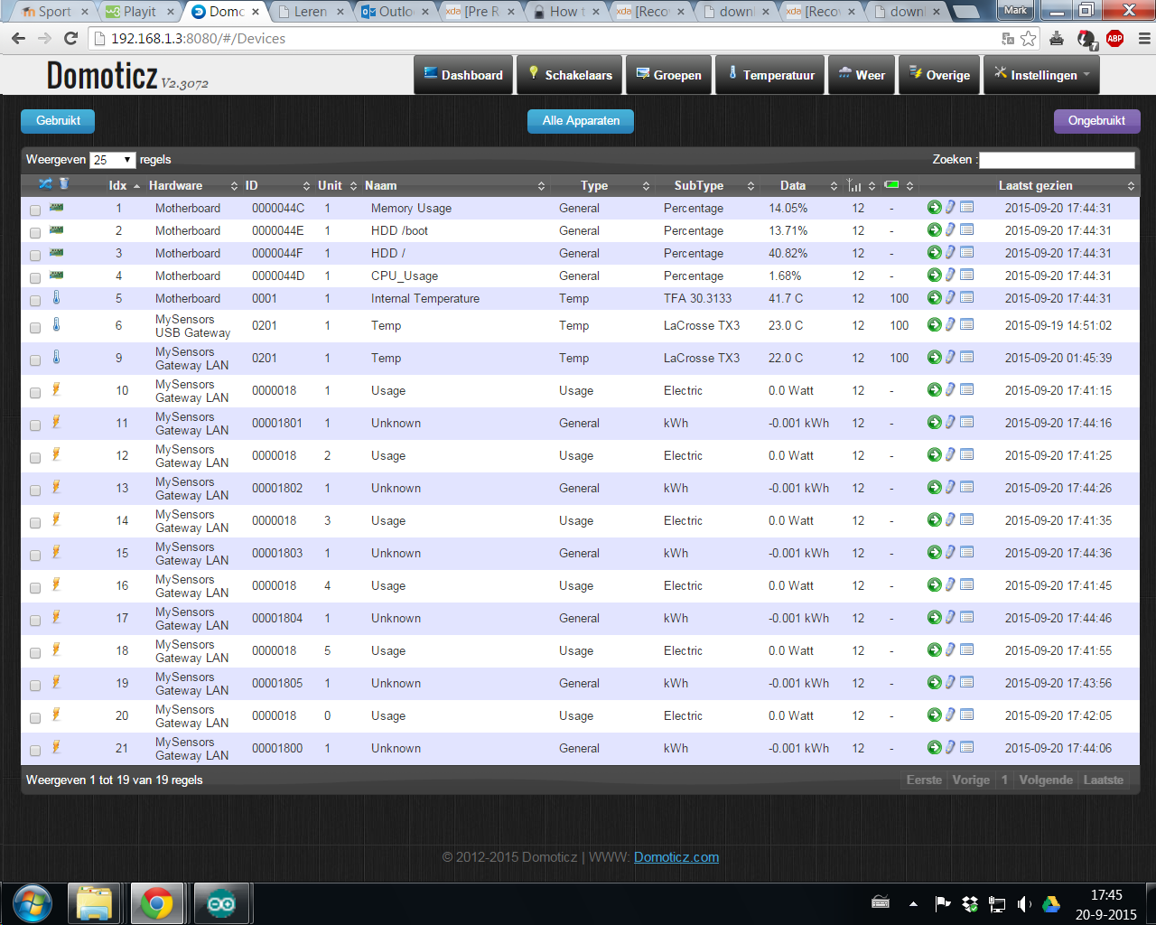
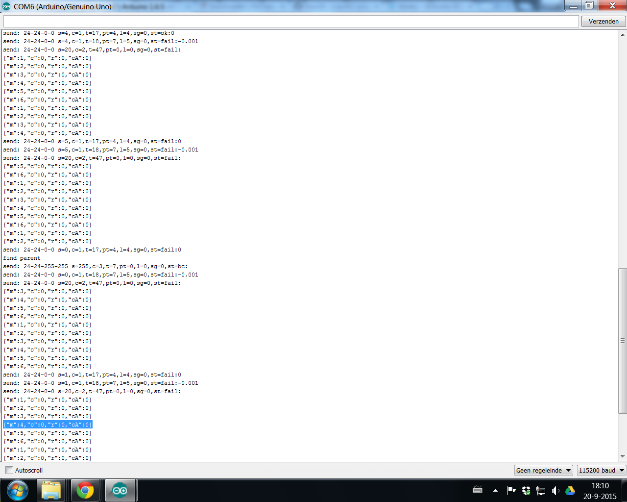
The serial on the master arduino says:
There's not more than a tiny plaster wall between the two arduinos, a total distance of one meter...
-
AWI I got it up and running with your new sketches!! :smiley:
Great work!!!!! Domoticz recognizes that there are sensors in the network.But something is still wrong, the usage isn't going up..
Whats wrong?Didn't connect a display and rotaryswitch and also didn't commented things out..
Why does it show every sensor twice? One with subtype unknown and one with electric??
I also seen that with the humidity temp sensor..The serial on the master arduino says:
There's not more than a tiny plaster wall between the two arduinos, a total distance of one meter...
@MarkV A few thing from what I read from the serial out:
-
The slave does not sense any pulses, all the values are at 0
-
The master gets a "fail" when sending data to the Gateway. Looks like a communication issue
-
Are you using an USB or LAN gateway. The Domoticz output show both.... I don't know if Domoticz can handle that.
-
You can try to delete the "old"/previous nodes and start the thing again. Domoticz should use a combined Usage/ Power sensor
-
-
Hi, great work :+1:
as my S0 meter uses 2000imp/kwh and my reading seem to be twice as high as they should be i guess your meters do 1000imp/kwh?
As i am still working on my programming skills i could not figure out where to change this :flushed:
can you give me a hint which 1000 to change out with my 2000?thanks!
@jeti You are right, I never thought about other meters than the 1 pulse = 1 Whr ones..sorry. There are a few ways of getting it changed:
-
You can keep leave most as it is and when you send/ or display the values divide the pulses by two and double the Watt values in the routines "LCD_local_display" and "sendPowerUpdate"
-
or: make the necessary calculations when the data comes in. This is a little more complicated in routine "storeMeterJSON" but if you understand the logic (including error corrrection) should be not too hard.
-
-
@MarkV A few thing from what I read from the serial out:
-
The slave does not sense any pulses, all the values are at 0
-
The master gets a "fail" when sending data to the Gateway. Looks like a communication issue
-
Are you using an USB or LAN gateway. The Domoticz output show both.... I don't know if Domoticz can handle that.
-
You can try to delete the "old"/previous nodes and start the thing again. Domoticz should use a combined Usage/ Power sensor
@AWI
I´m using a LAN GW, i disconnected the serial and made the LAN one of it.
Mmm, the comms error is strange, they're at max one meter apart, with a tiny plaster wall in between, both also got a cap between vcc and gnd.
Next weekend i´m going to have a look at the slave input, rather strange that it doesn´t receives pulses.
I connected the 5volt line to all the 6 pulse meters and connected their output to D2 - D8, through a cord of network cable.
Thanks for all your help so far!!!!! -
-
@AWI
I´m using a LAN GW, i disconnected the serial and made the LAN one of it.
Mmm, the comms error is strange, they're at max one meter apart, with a tiny plaster wall in between, both also got a cap between vcc and gnd.
Next weekend i´m going to have a look at the slave input, rather strange that it doesn´t receives pulses.
I connected the 5volt line to all the 6 pulse meters and connected their output to D2 - D8, through a cord of network cable.
Thanks for all your help so far!!!!! -
Dawm maybe thats the problem..
I connected the 5v as commen to the pulse + and the - to the digital inputs.So to be sure i need to connect the pulse + to the digitale inputs and the pulse - to gnd????
@MarkV I would depend on your S0 meters, but normal is "open collector" so you can connect '-' to ground and '+' to the input (= pull-up to Vcc).
(another way to connect is + to vcc and - to input, but then you need external "pull down" resistors and change the sketch)
-
Then thats the problem with the slave arduino getting no data. I connected the pulse output like you mentioned second and didn't changed the sketch.
Maybe i'm home tomorrow then i will give it a try.
Or is it hard to chsnge the sketch? And what should i change? -
Then thats the problem with the slave arduino getting no data. I connected the pulse output like you mentioned second and didn't changed the sketch.
Maybe i'm home tomorrow then i will give it a try.
Or is it hard to chsnge the sketch? And what should i change?@MarkV it is indicated in the sketch but you also need external resistors for pull-down. If you disable the internal pull-up resistors the levels are inverted. So you also need to'invert' the measurements or you are measuring the pulse width instead of the time between pulses.
-
Tonight i checked the wires and changed them and i believe your wright, the output is:
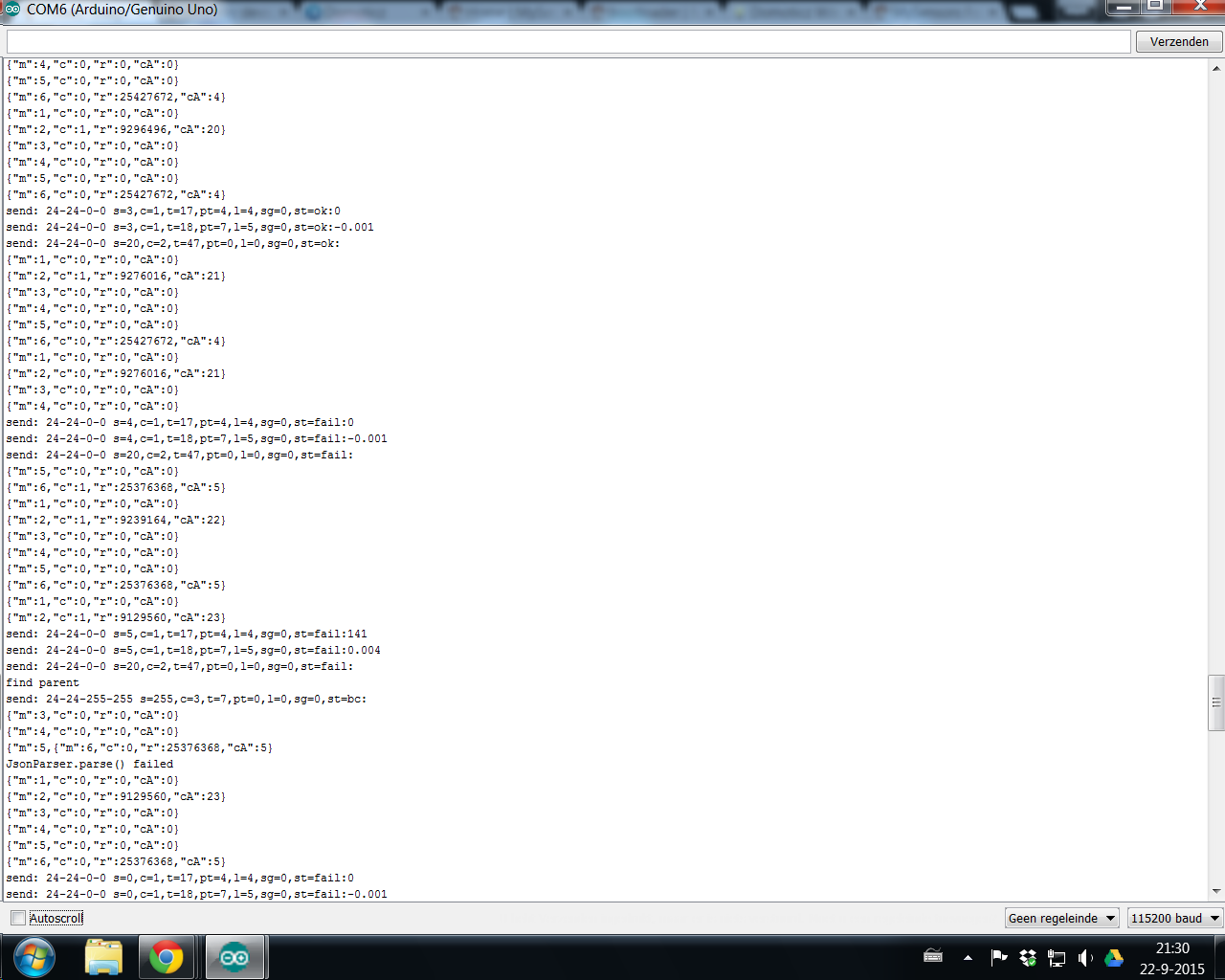
But it keeps giving a error, so i hangt them near each other with approx. 10cm space in between, why does it stil say fail after a good startup with ok and after 10a20sec it starts saying fail..
Is the readout correct?
And what more could cause the fail error? -
Tonight i checked the wires and changed them and i believe your wright, the output is:
But it keeps giving a error, so i hangt them near each other with approx. 10cm space in between, why does it stil say fail after a good startup with ok and after 10a20sec it starts saying fail..
Is the readout correct?
And what more could cause the fail error? -
the code for the measurement device::
//--------------------------------------------------------------------------------------------- // Arduino Pulse Counting Sketch for counting pulses from up to 12 pulse output meters. // uses direct port manipulation to read from each register of 6 digital inputs simultaneously // // Licence: GNU GPL // part of the openenergymonitor.org project // // Author: Trystan Lea // AWI: adapted to produce JSON and error checking at client side. //--------------------------------------------------------------------------------------------- //--------------------------------------------------------------------------------------------- // Pulse Counting Class - could be placed in seperate library... //--------------------------------------------------------------------------------------------- class PulseOutput { public: //AWI: access to all boolean pulse(int,int,unsigned long); //Detects pulses, in pulseLib.ino unsigned long rate( unsigned long ); //Calculates rate unsigned long count; //pulse count accumulator unsigned long countAccum; //pulse count total accumulator for extended error checking (only resets at startup) unsigned long prate; //pulse width in time unsigned long prateAccum; //pulse rate accumulator for calculating mean. private: boolean ld,d; //used to determine pulse edge unsigned long lastTime,time; //used to calculate rate }; //--------------------------------------------------------------------------------------------- // Variable declaration //--------------------------------------------------------------------------------------------- //CHANGE THIS TO VARY RATE AT WHICH PULSE COUNTING ARDUINO SPITS OUT PULSE COUNT+RATE DATA //time in seconds; const unsigned long printTime = 1000000; // delay between serial outputs in us (one meter at a time) const int lastMeter = 7 ; // is number of meters + 1 byte curMeter = 2 ; // current meter for serial output, wraps from 2 to lastMeter //--------------------------------------------------------------------------------------------- PulseOutput p[14]; //Pulse output objects int a,b,la,lb; //Input register variables unsigned long ltime, time; //time variables void setup() { // take care: pull-up inverses state! line 155 //setup input pins here with pull_up, else (default) float pinMode( 2, INPUT_PULLUP); pinMode( 3, INPUT_PULLUP); pinMode( 4, INPUT_PULLUP); pinMode( 5, INPUT_PULLUP); pinMode( 6, INPUT_PULLUP); pinMode( 7, INPUT_PULLUP); pinMode( 8, INPUT_PULLUP); pinMode( 9, INPUT_PULLUP); pinMode(10, INPUT_PULLUP); pinMode(11, INPUT_PULLUP); pinMode(12, INPUT_PULLUP); pinMode(13, INPUT_PULLUP); Serial.begin(115200); //standard serial DDRD = DDRD | B00000000; DDRB = DDRD | B00000000; } void loop() { la = a; //last register a used to detect input change lb = b; //last register b used to detect input change //-------------------------------------------------------------------- // Read from input registers //-------------------------------------------------------------------- a = PIND >> 2; //read digital inputs 2 to 7 really fast b = PINB; //read digital inputs 8 to 13 really fast time = micros(); if (la!=a || lb!=b) { //-------------------------------------------------------------------- // Detect pulses from register A //-------------------------------------------------------------------- p[2].pulse(0,a,time); //digital input 2 p[3].pulse(1,a,time); // '' 3 p[4].pulse(2,a,time); // '' etc p[5].pulse(3,a,time); p[6].pulse(4,a,time); p[7].pulse(5,a,time); //-------------------------------------------------------------------- // Detect pulses from register B //-------------------------------------------------------------------- p[8].pulse(0,b,time); //digital input 8 p[9].pulse(1,b,time); //etc p[10].pulse(2,b,time); p[11].pulse(3,b,time); p[12].pulse(4,b,time); p[13].pulse(5,b,time); } //-------------------------------------------------------------------- // Spit out data every printTime sec (time here is in microseconds) //-------------------------------------------------------------------- // build JSON: for all counters print Count (W), Count Accum(W), Average ms // Format {"m":meter,"c":count,"r":rate, "cA":countAccum} if ((time-ltime)>(printTime)) { ltime = time; //Print timer { Serial.print("{\"m\":"); Serial.print(curMeter-1); //Print meter number Serial.print(",\"c\":"); Serial.print(p[curMeter].count); //Print pulse count Serial.print(",\"r\":"); Serial.print(p[curMeter].rate(time)); //Print pulse rate p[curMeter].countAccum += p[curMeter].count; //Increment and print count accumulator to allow for error checking at client side; Serial.print(",\"cA\":"); Serial.print(p[curMeter].countAccum); Serial.println("}"); p[curMeter].count = 0; //Reset count (we just send count increment) p[curMeter].prateAccum = 0; //Reset accum so that we can calculate a new average } curMeter++ ; if (curMeter > lastMeter){ // wrap a around if passed last meter curMeter = 2;} } } // library for pulse, originally in separate file //----------------------------------------------------------------------------------- //Gets a particular input state from the register binary value // A typical register binary may look like this: // B00100100 // in this case if the right most bit is digital pin 0 // digital 2 and 5 are high // The method below extracts this from the binary value //----------------------------------------------------------------------------------- #define BIT_TST(REG, bit, val)( ( (REG & (1UL << (bit) ) ) == ( (val) << (bit) ) ) ) //----------------------------------------------------------------------------------- // Method detects a pulse, counts it, finds its rate, Class: PulseOutput //----------------------------------------------------------------------------------- boolean PulseOutput::pulse(int pin, int a, unsigned long timeIn) { ld = d; //last digital state = digital state if (BIT_TST(a,pin,1)) d = 1; else d = 0; //Get current digital state from pin number // if (ld==0 && d==1) // no internal pull_up if state changed from 0 to 1: internal pull-up inverts state if (ld==1 && d==0) //pull_up f state changed from 0 to 1: internal pull-up inverts state { count++; //count the pulse // Rate calculation lastTime = time; time = timeIn ; // correction to allow for processing prate = (time-lastTime);// - 400; //rate based on last 2 pulses //-190 is an offset that may not be needed...?? prateAccum += prate - 2000; //accumulate rate for average calculation return 1; } return 0; } //----------------------------------------------------------------------------------- // Method calculates the average rate based on multiple pulses (if there are 2 or more pulses) //----------------------------------------------------------------------------------- unsigned long PulseOutput::rate(unsigned long timeIn) { if (count > 1) { prate = prateAccum / count; //Calculate average } else { if ((timeIn - lastTime)>(prate*2)) prate = 0;} //Decrease rate if no pulses are received //in the expected time based on the last //pulse width. return prate; }@AWI
Your measurement sketch is really nice. There is one line I do not understand.prateAccum += prate - 2000;
Is this prateAccum needed or couldn't it be left away? What is the meaning of 2000 in this context?
Cu,
FotoFieber -
@AWI
Your measurement sketch is really nice. There is one line I do not understand.prateAccum += prate - 2000;
Is this prateAccum needed or couldn't it be left away? What is the meaning of 2000 in this context?
Cu,
FotoFieber@FotoFieber To be honest .. a left over from some experiments. Just leave it out... you won't notice the difference.
-
@AWI thanks again!
I am using your sketches with only one S0 Meter (the 2000pulse/kwh one).
*One thing i just found out, that as long as the master arduino is connected to the serial port of my pc it is running fine but when its not, it does not send.I have checked the voltage at the radio and it is the same... I also do not have any display or rotary encoder, as I do the visualisation with FHEM.
Do you know why this is the case? * -> Voltage was to low... but the secon question remains:Any idea to use differen pulses/kwh S0 meters? for example one 2000pulse/kwh and one 800 pulse/kwh.
thanks in advance! -
Arduino: 1.6.5 (Windows 7), Board:"Arduino Nano, ATmega328"
sketch_oct03e:128: error: 'V_TEXT' was not declared in this scope
sketch_oct03e.ino: In function 'void setup()':
sketch_oct03e:162: error: 'S_INFO' was not declared in this scope
sketch_oct03e.ino: In function 'void loop()':
sketch_oct03e:337: error: 'V_TEXT' was not declared in this scope
sketch_oct03e.ino: In function 'void incomingMessage(const MyMessage&)':
sketch_oct03e:364: error: 'V_TEXT' was not declared in this scope
'V_TEXT' was not declared in this scopeDit rapport zou meer informatie hebben met
"Tijdens de compilatie uitgebreide uitvoer weergeven"
ingeschakeld in Bestand > Voorkeuren. -
Arduino: 1.6.5 (Windows 7), Board:"Arduino Nano, ATmega328"
sketch_oct03e:128: error: 'V_TEXT' was not declared in this scope
sketch_oct03e.ino: In function 'void setup()':
sketch_oct03e:162: error: 'S_INFO' was not declared in this scope
sketch_oct03e.ino: In function 'void loop()':
sketch_oct03e:337: error: 'V_TEXT' was not declared in this scope
sketch_oct03e.ino: In function 'void incomingMessage(const MyMessage&)':
sketch_oct03e:364: error: 'V_TEXT' was not declared in this scope
'V_TEXT' was not declared in this scopeDit rapport zou meer informatie hebben met
"Tijdens de compilatie uitgebreide uitvoer weergeven"
ingeschakeld in Bestand > Voorkeuren.@marten You need to use the "Development" branch of MySensors until the production version gets updated -or- you can uncomment the lines with "const int ..."
// new V_TEXT variable type (development 20150905) //const int V_TEXT = 47 ; // new S_INFO sensor type (development 20150905) //const int S_INFO = 36 ; -
@AWI thanks again!
I am using your sketches with only one S0 Meter (the 2000pulse/kwh one).
*One thing i just found out, that as long as the master arduino is connected to the serial port of my pc it is running fine but when its not, it does not send.I have checked the voltage at the radio and it is the same... I also do not have any display or rotary encoder, as I do the visualisation with FHEM.
Do you know why this is the case? * -> Voltage was to low... but the secon question remains:Any idea to use differen pulses/kwh S0 meters? for example one 2000pulse/kwh and one 800 pulse/kwh.
thanks in advance!@jeti as mentioned in a previous post..
There are a few ways of getting it changed:
You can keep/ leave most as it is and when you send/ or display the values divide the pulses by two and double the Watt values in the routines "LCD_local_display" and "sendPowerUpdate"
or: make the necessary calculations when the data comes in. This is a little more complicated in routine "storeMeterJSON" but if you understand the logic (including error corrrection) should be not too hard.
I don't have the time at this moment to do it for you...
Hello! It looks like you're interested in this conversation, but you don't have an account yet.
Getting fed up of having to scroll through the same posts each visit? When you register for an account, you'll always come back to exactly where you were before, and choose to be notified of new replies (either via email, or push notification). You'll also be able to save bookmarks and upvote posts to show your appreciation to other community members.
With your input, this post could be even better 💗
Register Login