How To - Doorbell Automation Hack
-
Tried that sketch (with just changing pin assignments and flipping the relay high/low settings). As soon as I powered it up, the relay started clicking every 4 seconds and it never appeared in Domoticz. I think it's because after the pin is set to input, there's " digitalWrite(FRONT_DOOR_BUTTON, HIGH);" command that's like someone holding the button down.
Went back to the original sketch I used. I changed from an auto NODE_ID to a fixed setting in the defines and re-uploaded it. The device appeared in Domoticz correctly! I've got a "doorbell sketch 1.0" with 3 devices - repeater, the doorbell button as a S_Motion, and the doorbell on/off as a S_Lights.
However, it still doesn't work. My wiring is shown above and it worked great under Vera. Now, I cannot get the doorbell to actually chime. Nor does the outdoor button do anything. I've verified the wiring, but shorting the A0 pin to the ground input doesn't do anything like it should. However, there's ANOTHER ground next to the A0 (under the wireless card), and if I short the A0 to that ground pin, the switch shows on in Domoticz. I can change the wiring since for some reason which ground I use is making a difference.
No matter what, still no relay action though. I tried turning the doorbell on/off switch both ways and it made no difference. In either setting, shorting the two pins turns the switch in Domoticz on.
I was comparing the two sketches (the one I'm using, and the dual-bell one). The single bell sketch sets the button pin with pinmode(Doorbell_pin, input_pullup) where the dual uses input without the pullup. Which should be right?
The sketch I use doesn't use internal pull ups; external only.
As for the relay clicking, could be either the jumper on the relay, or not enough current to power it properly.
Not sure why you are having issues with either of the scripts. What type of gateway do you use?
-
It's an ethernet gateway.
I don't think it's really a Mysensors issue though as I think about it - the doorbell should ring when you press the button whether you have the gateway running or not. And I'm not even getting that. In fact, I AM getting the signal to the gateway, but it's not activating the relay.
Is it possible that the doorbell on/off switch isn't working right in the code? I never used that before. I think I'll try tomorrow (kids in bed now, so can't really play around with a doorbell!) removing that switch for now and have it always set to on.
I looked through comparing the sketch I'm using now (the one drock1985 made that's for domoticz) and the original. The only change is moving the gw.send command and changing it slightly. But again, that shouldn't impact the bell physically working. So there's something else going on.
Is there a way to check if the code uploaded to the arduino correctly? I'm using the rboard and a FTDI to upload. I'm wondering if something isn't going weird there and it's not uploading correctly and that's why I'm getting different issues every time I try something...
-
Not really. You could try uploading at a slower speed. Slower speed over serial usually equals less chance of missed data.
Have you tried running this connected to your PC and viewing the data from serial console/window? Copy/paste the output from the serial monitor so we can see what's going on.
-
I have installed the doorbell sketch on my testboard. This just to see how it should be working. First sensor with a relay for me basically :)
But I have a question. I have use the sketch, I have two devices coming up in Domiticz, a security sensor and a light switch. But basically I don't get the function of these buttons?
I think the security sensor responds on the doorbell press?Also I think the other button is to activate the physical doorbell which could switch the relay? But I would expect that the security switch button in Domoticz could also activate the relay remotely, but this is not the case? Because, I don't see an option to switch the relay remotely in Domoticz?
So it is working; but any help is appreciated if somebody could explain the functionallity for me and if this is the expected behavior :)
I know when I was playing with Domoticz the Doorbell sketch would show up as a security light and a light for me. The security light I changed to a motion sensor in Domoticz (click edit on your dashboard/switches tab). After that when I pressed the doorbell button, the motion sensor would switch on to show the button was pressed, then immediately back off. Although for it to turn off automatically, I may have had to tell domoticz to do that after xx seconds, can't remember for sure now.
And yes you are correct, the second switch is a 'mute' for the doorbell. If off, the doorbell won't sound (switch the relay).
-
Hi guys,
I'm nearly there, but need a little help if anyone can!
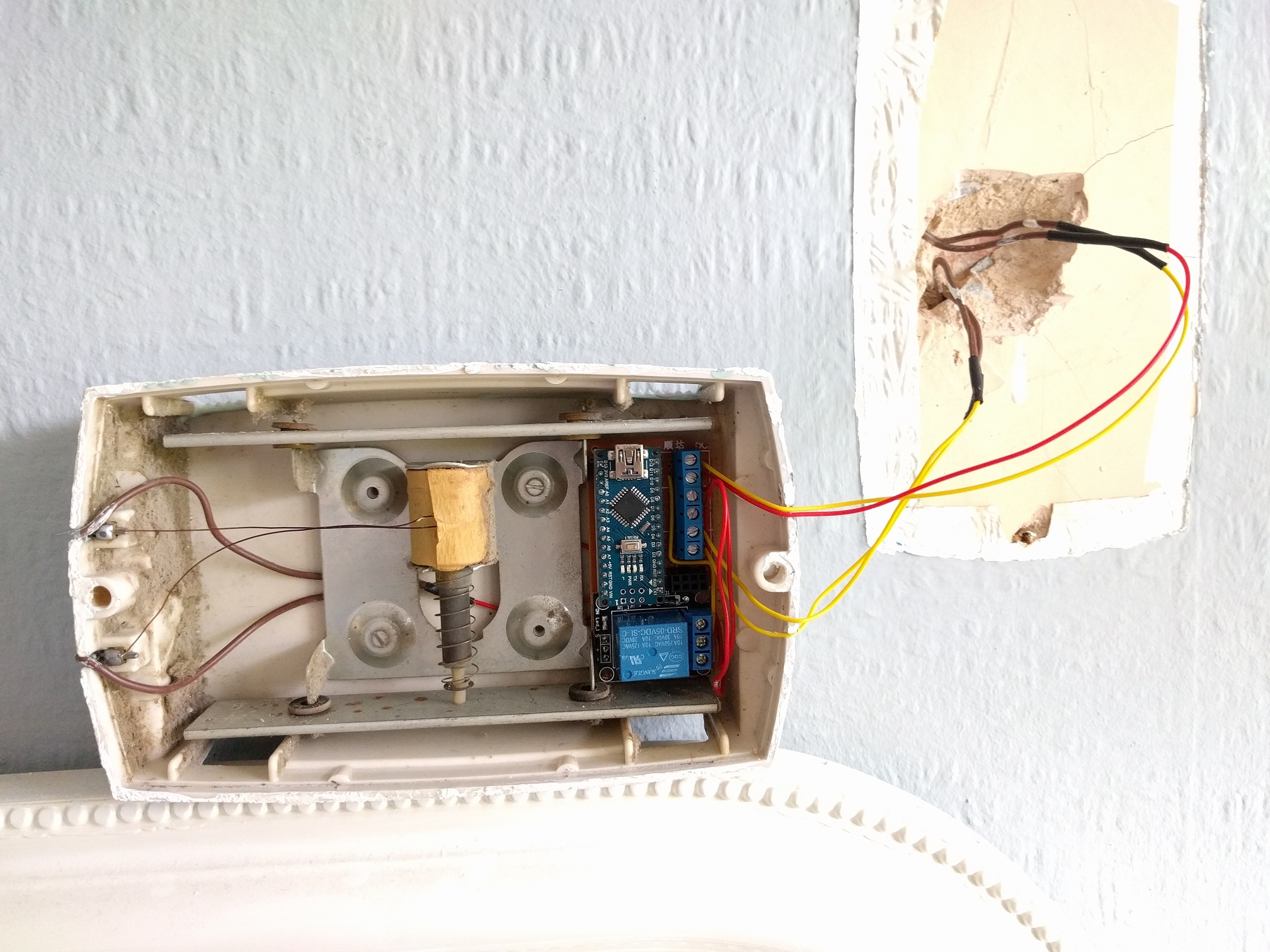
For my setup I've got a diode bridge followed immediately by a buck converter, so the doorbell's 18v AC comes down to 8v DC. My plan was to run the doorbell AND the arduino off this same supply, but I'm guessing now that it may not be possible. The reason for this was down to there only being 2 wires to the doorbell. The doorbell works fine off 8v DC and so does the arduino. The issue however is when i both power the arduino and the doorbell at the same time of the same supply. The relay opens and then the arduino resets. No chime.
What should I do? Wiring layout is exactly the same as above but the 8v DC loops through the relay to the doorbell as well as going to VIN/GND on the Arduino Nano.
I can't have the arduino at the power supply end as I need the doorbell button connections, so I'm hoping someone might have some ideas around splitting out the power supplies at the doorbell end? Or smoothing it or something like that.
Power is red/yellow from the wall. Doorbell button is yellow/yellow from the wall. brown/brown is soldered/heat shrunk to red/red within the housing. NRF is on headers, so it's lifted out in this photo.
Thanks,
Patrick
-
Or can i just get away with a better power supply for the both? Essentially I've got a pulse-detecting mysensors node, a doorbell node and a doorbell itself running off a cheap-ass ebay chinese full-bridge rectifier and step-down converter (120v AC > 8v DC). The doorbell takes 8v DC so I'm using that as the common voltage.
-
Hi guys,
I'm nearly there, but need a little help if anyone can!
For my setup I've got a diode bridge followed immediately by a buck converter, so the doorbell's 18v AC comes down to 8v DC. My plan was to run the doorbell AND the arduino off this same supply, but I'm guessing now that it may not be possible. The reason for this was down to there only being 2 wires to the doorbell. The doorbell works fine off 8v DC and so does the arduino. The issue however is when i both power the arduino and the doorbell at the same time of the same supply. The relay opens and then the arduino resets. No chime.
What should I do? Wiring layout is exactly the same as above but the 8v DC loops through the relay to the doorbell as well as going to VIN/GND on the Arduino Nano.
I can't have the arduino at the power supply end as I need the doorbell button connections, so I'm hoping someone might have some ideas around splitting out the power supplies at the doorbell end? Or smoothing it or something like that.
Power is red/yellow from the wall. Doorbell button is yellow/yellow from the wall. brown/brown is soldered/heat shrunk to red/red within the housing. NRF is on headers, so it's lifted out in this photo.
Thanks,
Patrick
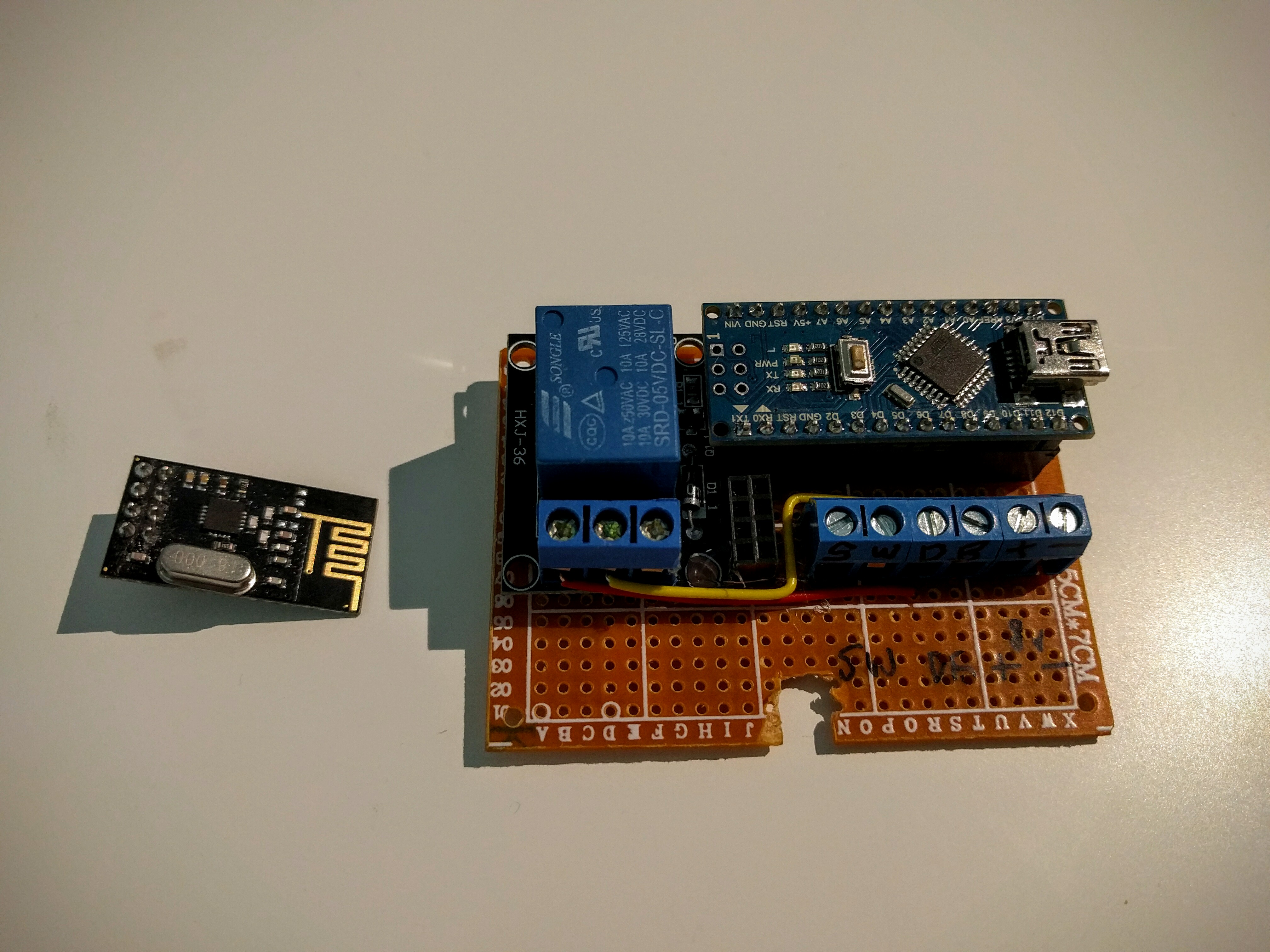
@pjblink - what are the components you have built in there? I see the Arduino Nano and a relay - are they all attached to a board? Is there a radio in there, too? I clicked on the (old) link above for Mini RBoard, but I get a gateway error when going to the page to purchase...
-
Hi crodgers,
So yeh, there's a nano on headers, relay, nrf on headers and 3 wire terminals - 1 for the doorbell button, 1 for the bell itself and another for the DC IN. Everything is soldered to a prototyping board which has now been trimmed down to fit in the doorbell housing.
Thanks,
Patrick
-
Working without the doorbell load attached:
mysensors enabled doorbell working without loadFailing when I attach the load:
mysensors enabled doorbell failing with load -
I've just tried it with both 1000uF and then a 4700uF cap across VIN/GND on the arduino with only slightly better results. It'll ring, but the relay stays open most of the time and the arduino needs resetting to release it :(
@pjblink - late into the discussion, but have you tried changing to another power supply or another regulator? It might that its to unstable for your node... atleast temporary to rule things out.
Controller: Proxmox VM - Home Assistant
MySensors GW: Arduino Uno - W5100 Ethernet, Gw Shield Nrf24l01+ 2,4Ghz
MySensors GW: Arduino Uno - Gw Shield RFM69, 433mhz
RFLink GW - Arduino Mega + RFLink Shield, 433mhz -
@pjblink - late into the discussion, but have you tried changing to another power supply or another regulator? It might that its to unstable for your node... atleast temporary to rule things out.
@sundberg84 That was definitely on the cards...but it looks like I might have got it working. I did 4 things in one go, which is unlike me, so now I have to break things down to see which one helped (if it wasn't all)...1st thing was a 4700uF cap over the arduino VIN/GND, 2nd was a 1000uF cap over the relay +- 5v,… 3rd was to reflow a few of the GND solders and finally I dropped the voltage regulator from 8v to just under 7v...and hey presto...
-
@sundberg84 That was definitely on the cards...but it looks like I might have got it working. I did 4 things in one go, which is unlike me, so now I have to break things down to see which one helped (if it wasn't all)...1st thing was a 4700uF cap over the arduino VIN/GND, 2nd was a 1000uF cap over the relay +- 5v,… 3rd was to reflow a few of the GND solders and finally I dropped the voltage regulator from 8v to just under 7v...and hey presto...
@pjblink - a bad ground connection has been a pain for me alot of times... good you got it working.
-
So it kept failing after 2 or 3 rings...frustrating! I enabled all the debug and noticed it kept failing just before sending out the "off" message. It didn't reset, just stalled. This was the case even when powered by USB. And then I remembered how sensitive the NRFs are to fluctuations in power and I hadn't got round to putting a cap on there yet!!! I put a spare 1000uF (47uF are on order) and so far it hasnt caused me any further issues! So now I've got 3 huge capacitors on there, and it looks ok...touch wood.
-
How are you powering the relay? Are you trying to run it directly from an arduino data line? If so, that could be your problem. I am currently working on a motion sensor light with a PIR, LDR, and a relay. Now the relay I am using is a 12 volt relay, but the concept would be the same for a 5 volt relay. The idea is to use a transistor to trigger the relay from a separate power source. I used an 2N3904 NPN transistor to switch the the negative side of the power to the relay. You simply connect the emitter to your ground, the collector to the negative side of your relay and the base goes to your arduino data pin. You may need to add a pull-down resistor on the transistor base to ground depending on your situation. In my case it worked fine without it. Also, you should still of course put your flyback diode across your relay coil to prevent voltage spikes.
The above assumes that you are using a relay on it's own and not a relay module like the ones you find on ebay. The relay modules already have the transistor and diode already built in, and some even use an optocoupler for added isolation.
-
My test situation is Nano+Radio with double relay module and push button for the bell. Relay is powered by the 5V by Arduino, and i have tested this with the example sketch (+modification for double relay) and everything was working fine. The issue i am having is the original sketch (1 bell + 1 relay) is made for mysensors 1.x, and i am running 2.x and have no idea how te rewrite this.