My Slim 2AA Battery Node
-
Hello @m26872 it is me again if you do remember me.
Just wanted to tell you that I ordered the boards 5 weeks ago and it was delivered to Egypt after 2 weeks, and the silly customs requested some security approvals to give me the boards which I couldn't do it till now. Something pathetic which makes me laugh :)
Can't wait to do my nodes !
@ahmedadelhosni Welcome back! Yes I remember you had to struggle and could not buy common 433MHz remote controlled switches. Makes sense to do diy projects then I guess.
Hope you get your new nodes running. Please share your result. -
@ahmedadelhosni Welcome back! Yes I remember you had to struggle and could not buy common 433MHz remote controlled switches. Makes sense to do diy projects then I guess.
Hope you get your new nodes running. Please share your result.@m26872 You are right.
I'll go tomorrow and try to get the approval :) Well back soon
-
Finally !
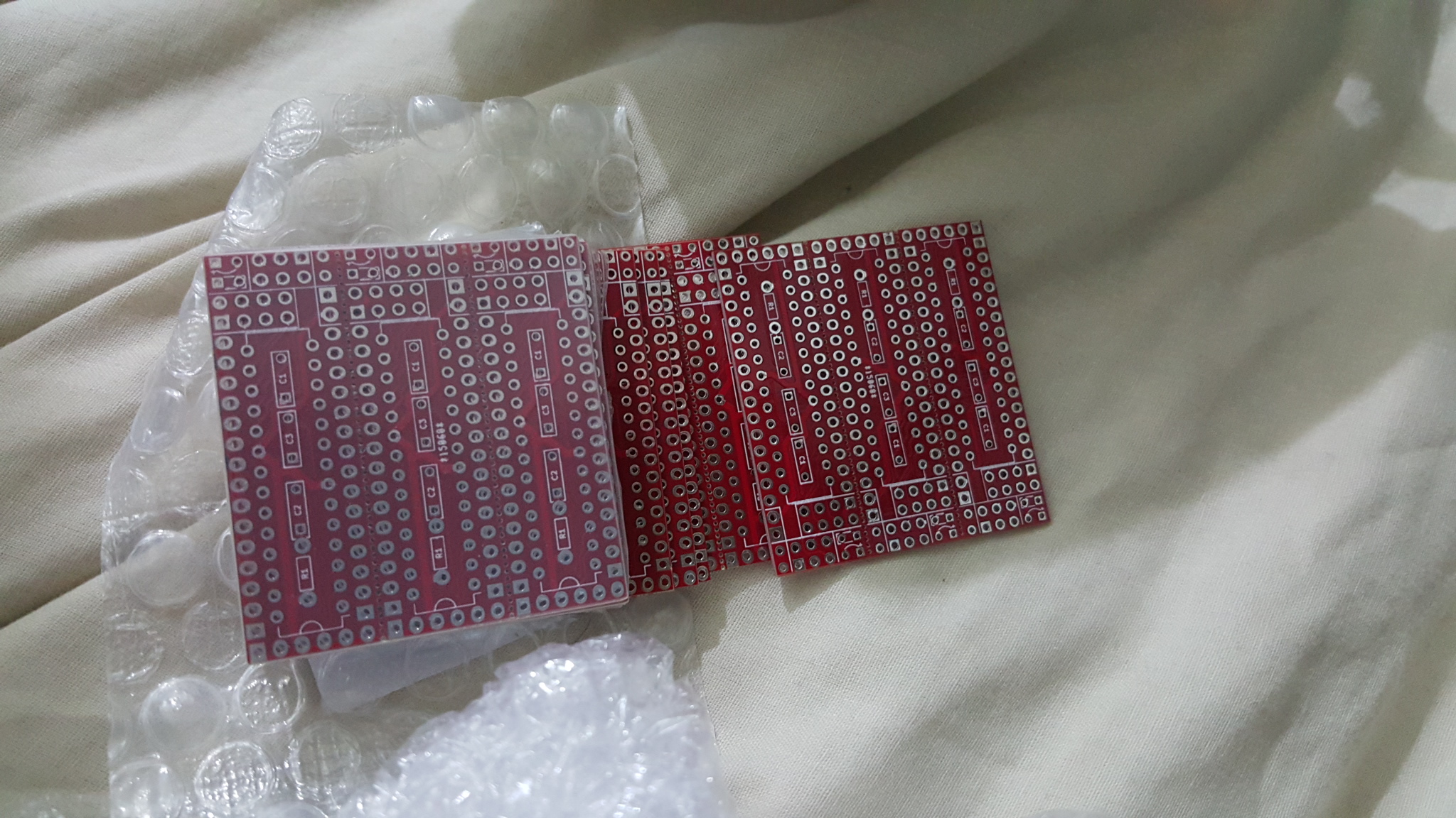
11 pcbs. But I am really angry and feel bad from what happened by DHL.
I paid 29$ for shipping and here in Egypt i paid stupid fees for customs and several things equal to 38$ !!!!! I dont know wether this is something related to my country Egypt or not :(I' ll try to forget all what I paid when I do my first node.
-
@ahmedadelhosni that really sucks :disappointed:
-
Hello all,
I have been struggling with this for a couple of weeks now and I just can seem to figure out a good way to upload sketches to the arduio328p-pu. First of all I use this setup;
I use arduino for mac 1.6.5
I use a breadboard with a crystal, two capacitors and a resistor between reset and 5v.
An arduino to burn bootloader (with the chip inserted and sketch arduinoISP uploaded).
I use the same hex files as you guys with 1a. I used the optiboot 9600 BOD, just the 9600 and the 4800. Uploading the bootloader is no problem at all. Arduino ide burns the bootloader without any problems. However when I try to upload the sketches I get different errors. The “Yikes” version in which it states that my device signature is not ok and programmer not responding. I use upload using programmer.So, I tried to upload the arduino uno version to rule out all miscabling. So what I did was upload the arduino uno bootloader, tried to upload the blink sketch afterwards and it works. So my cables are ok….
I thought to repeat the exact same process with the boot version above. However no succes, I keep getting stuck at uploading sketches. Is it just not possible?
I read about setting the fuse options and I read that when you define these in the boards.txt, they will be set as the fuseparameters. When I check the boards txt above i see that fuse settings are: L0x62,H0xde,E0x07, however when I open the png file (first post, fuse settings) it states L0x62,H0xDE,E0xFF. Furthermore the lockbits are at 0xCF, compared to the boards.txt 0x2F. What is true and how should I set these. I don’t see a possibility in arduino ide (I use another arduino to upload, so I don’t have a tiny or USBASP.
Help would be much appreciated here because I have like 30 boards sitting catching dust.
-
@ahmedadelhosni : no luck! Here same for us in France. I think it's because they handle our package from airport to house...but have we not already paid for this! There is vat of course too, but here vat+15euro extra mystical handle fee.
Fun, is when you want to make a joke to the dhl person and you ask why fees, I don't want pay, give me my package, no come back!! ahaha they are not funny :) At less, if they were doing right their job, 4times/10 they say "you were not here"??? yep, but I was there..and where is the paper in my mailbox, nothing...arrgh! what do you think I will wait you on the road???No matter, looking at your package, I think you will have lot of fun :)
@scalz Seeing that someone else had the same issue made me better hahaha :)
The problem that I went myself to take it today and they told me that I have to buy for the customs and the government.I need to calm down and have fun better. Thanks :)
-
Hello all,
I have been struggling with this for a couple of weeks now and I just can seem to figure out a good way to upload sketches to the arduio328p-pu. First of all I use this setup;
I use arduino for mac 1.6.5
I use a breadboard with a crystal, two capacitors and a resistor between reset and 5v.
An arduino to burn bootloader (with the chip inserted and sketch arduinoISP uploaded).
I use the same hex files as you guys with 1a. I used the optiboot 9600 BOD, just the 9600 and the 4800. Uploading the bootloader is no problem at all. Arduino ide burns the bootloader without any problems. However when I try to upload the sketches I get different errors. The “Yikes” version in which it states that my device signature is not ok and programmer not responding. I use upload using programmer.So, I tried to upload the arduino uno version to rule out all miscabling. So what I did was upload the arduino uno bootloader, tried to upload the blink sketch afterwards and it works. So my cables are ok….
I thought to repeat the exact same process with the boot version above. However no succes, I keep getting stuck at uploading sketches. Is it just not possible?
I read about setting the fuse options and I read that when you define these in the boards.txt, they will be set as the fuseparameters. When I check the boards txt above i see that fuse settings are: L0x62,H0xde,E0x07, however when I open the png file (first post, fuse settings) it states L0x62,H0xDE,E0xFF. Furthermore the lockbits are at 0xCF, compared to the boards.txt 0x2F. What is true and how should I set these. I don’t see a possibility in arduino ide (I use another arduino to upload, so I don’t have a tiny or USBASP.
Help would be much appreciated here because I have like 30 boards sitting catching dust.
@betonishard A few "unused" bits of the Ext fuses are differently written in avrdude (Arduino IDE) and Atmel IDE programmer implemetation. That's why the same settings can look different. You have to know which one you use.
Search for "Avr fuse calculator" on the internet and some will show you fuses for both methods.I also had issues with avrdude when I started and never got it to work. A lot of others do of course, but I found the Atmel way easier for me. Hence only this is shown in the pictures. The bootloading business is not easy and a lot of info is availible on the arduino forums. I think the only way is to read and study.
-
Hello all,
I have been struggling with this for a couple of weeks now and I just can seem to figure out a good way to upload sketches to the arduio328p-pu. First of all I use this setup;
I use arduino for mac 1.6.5
I use a breadboard with a crystal, two capacitors and a resistor between reset and 5v.
An arduino to burn bootloader (with the chip inserted and sketch arduinoISP uploaded).
I use the same hex files as you guys with 1a. I used the optiboot 9600 BOD, just the 9600 and the 4800. Uploading the bootloader is no problem at all. Arduino ide burns the bootloader without any problems. However when I try to upload the sketches I get different errors. The “Yikes” version in which it states that my device signature is not ok and programmer not responding. I use upload using programmer.So, I tried to upload the arduino uno version to rule out all miscabling. So what I did was upload the arduino uno bootloader, tried to upload the blink sketch afterwards and it works. So my cables are ok….
I thought to repeat the exact same process with the boot version above. However no succes, I keep getting stuck at uploading sketches. Is it just not possible?
I read about setting the fuse options and I read that when you define these in the boards.txt, they will be set as the fuseparameters. When I check the boards txt above i see that fuse settings are: L0x62,H0xde,E0x07, however when I open the png file (first post, fuse settings) it states L0x62,H0xDE,E0xFF. Furthermore the lockbits are at 0xCF, compared to the boards.txt 0x2F. What is true and how should I set these. I don’t see a possibility in arduino ide (I use another arduino to upload, so I don’t have a tiny or USBASP.
Help would be much appreciated here because I have like 30 boards sitting catching dust.
@betonishard said:
Hello all,
I have been struggling with this for a couple of weeks now and I just can seem to figure out a good way to upload sketches to the arduio328p-pu. First of all I use this setup;
I use arduino for mac 1.6.5
I use a breadboard with a crystal, two capacitors and a resistor between reset and 5v.
An arduino to burn bootloader (with the chip inserted and sketch arduinoISP uploaded).
I use the same hex files as you guys with 1a. I used the optiboot 9600 BOD, just the 9600 and the 4800. Uploading the bootloader is no problem at all. Arduino ide burns the bootloader without any problems. However when I try to upload the sketches I get different errors. The “Yikes” version in which it states that my device signature is not ok and programmer not responding. I use upload using programmer.So, I tried to upload the arduino uno version to rule out all miscabling. So what I did was upload the arduino uno bootloader, tried to upload the blink sketch afterwards and it works. So my cables are ok….
I thought to repeat the exact same process with the boot version above. However no succes, I keep getting stuck at uploading sketches. Is it just not possible?
I read about setting the fuse options and I read that when you define these in the boards.txt, they will be set as the fuseparameters. When I check the boards txt above i see that fuse settings are: L0x62,H0xde,E0x07, however when I open the png file (first post, fuse settings) it states L0x62,H0xDE,E0xFF. Furthermore the lockbits are at 0xCF, compared to the boards.txt 0x2F. What is true and how should I set these. I don’t see a possibility in arduino ide (I use another arduino to upload, so I don’t have a tiny or USBASP.
Help would be much appreciated here because I have like 30 boards sitting catching dust.
Hi, i had the same problem, but then i tried the 1b hex and since i burned this it works for me.
-
Makes sense to me. By closing the contact you get a path from 3V3 via the pullup resistor to ground.
The current is (for a pullup resistor value around 30KOhm) around 100uA.
Try NOT using the internal pullup resistor of pin D3, and using an external pullup resistor of 1MOhm or more.
You will see lower current when the contact is closed.
@GertSanders said:
Makes sense to me. By closing the contact you get a path from 3V3 via the pullup resistor to ground.
The current is (for a pullup resistor value around 30KOhm) arounda lot of 100uA.
Try NOT using the internal pullup resistor of pin D3, and using an external pullup resistor of 1MOhm or more.
You will see lower current when the contact is closed.
Yesterday i get a lot of resistors, now i testen 1Mohm and the current draw is around 4 µa, but now the arduino do not recognize when the reedcontact is closed or open. When the contact is closed the current draw is 4 µa when opened 1.2µa
do i have to edit the sketch in order to get it to work? -
@meddie
The pull up 1MOhm resistor should go from Vcc - resistor - D2
The switch should be connected to D2 and Gnd
D2 needs to be defined as INPUT, no need to add the statement with PULLUP.
Post your sketch so we can have a look. -
/** * Created by Henrik Ekblad <henrik.ekblad@mysensors.org> * Copyright (C) 2013-2015 Sensnology AB * Full contributor list: https://github.com/mysensors/Arduino/graphs/contributors * * Documentation: http://www.mysensors.org * Support Forum: http://forum.mysensors.org * * This program is free software; you can redistribute it and/or * modify it under the terms of the GNU General Public License * version 2 as published by the Free Software Foundation. * ******************************* * * DESCRIPTION * * Interrupt driven binary switch example with dual interrupts * Author: Patrick 'Anticimex' Fallberg * Connect one button or door/window reed switch between * digitial I/O pin 3 (BUTTON_PIN below) and GND and the other * one in similar fashion on digital I/O pin 2. * This example is designed to fit Arduino Nano/Pro Mini * */ #include <MySensor.h> #include <SPI.h> #define SKETCH_NAME "Binary Sensor" #define SKETCH_MAJOR_VER "1" #define SKETCH_MINOR_VER "0" #define PRIMARY_CHILD_ID 3 #define SECONDARY_CHILD_ID 4 #define PRIMARY_BUTTON_PIN 2 // Arduino Digital I/O pin for button/reed switch #define SECONDARY_BUTTON_PIN 3 // Arduino Digital I/O pin for button/reed switch #if (PRIMARY_BUTTON_PIN < 2 || PRIMARY_BUTTON_PIN > 3) #error PRIMARY_BUTTON_PIN must be either 2 or 3 for interrupts to work #endif #if (SECONDARY_BUTTON_PIN < 2 || SECONDARY_BUTTON_PIN > 3) #error SECONDARY_BUTTON_PIN must be either 2 or 3 for interrupts to work #endif #if (PRIMARY_BUTTON_PIN == SECONDARY_BUTTON_PIN) #error PRIMARY_BUTTON_PIN and BUTTON_PIN2 cannot be the same #endif #if (PRIMARY_CHILD_ID == SECONDARY_CHILD_ID) #error PRIMARY_CHILD_ID and SECONDARY_CHILD_ID cannot be the same #endif MySensor sensor_node; // Change to V_LIGHT if you use S_LIGHT in presentation below MyMessage msg(PRIMARY_CHILD_ID, V_TRIPPED); MyMessage msg2(SECONDARY_CHILD_ID, V_TRIPPED); void setup() { sensor_node.begin(); // Setup the buttons pinMode(PRIMARY_BUTTON_PIN, INPUT); pinMode(SECONDARY_BUTTON_PIN, INPUT); // Activate internal pull-ups digitalWrite(PRIMARY_BUTTON_PIN, HIGH); digitalWrite(SECONDARY_BUTTON_PIN, HIGH); // Send the sketch version information to the gateway and Controller sensor_node.sendSketchInfo(SKETCH_NAME, SKETCH_MAJOR_VER"."SKETCH_MINOR_VER); // Register binary input sensor to sensor_node (they will be created as child devices) // You can use S_DOOR, S_MOTION or S_LIGHT here depending on your usage. // If S_LIGHT is used, remember to update variable type you send in. See "msg" above. sensor_node.present(PRIMARY_CHILD_ID, S_DOOR); sensor_node.present(SECONDARY_CHILD_ID, S_DOOR); } // Loop will iterate on changes on the BUTTON_PINs void loop() { uint8_t value; static uint8_t sentValue=2; static uint8_t sentValue2=2; // Short delay to allow buttons to properly settle sensor_node.sleep(5); value = digitalRead(PRIMARY_BUTTON_PIN); if (value != sentValue) { // Value has changed from last transmission, send the updated value sensor_node.send(msg.set(value==HIGH ? 1 : 0)); sentValue = value; } value = digitalRead(SECONDARY_BUTTON_PIN); if (value != sentValue2) { // Value has changed from last transmission, send the updated value sensor_node.send(msg2.set(value==HIGH ? 1 : 0)); sentValue2 = value; } // Sleep until something happens with the sensor sensor_node.sleep(PRIMARY_BUTTON_PIN-2, CHANGE, SECONDARY_BUTTON_PIN-2, CHANGE, 0); } ``` -
@meddie said:
// Activate internal pull-ups
digitalWrite(PRIMARY_BUTTON_PIN, HIGH);
digitalWrite(SECONDARY_BUTTON_PIN, HIGH);If you use the external pull up, you need to comment out these two lines like so:
// Activate internal pull-ups
// digitalWrite(PRIMARY_BUTTON_PIN, HIGH);
// digitalWrite(SECONDARY_BUTTON_PIN, HIGH);No need for an internal pullup if you use an external pull up.
In the above I'm assuming you have an external pullup resistor for each digital pin, one for D2 and one for D3. -
@ahmedadelhosni You know that the nRF pins are not centered? That means if you rotate it like this it will no longer be straight above the "slim node motherboard".
What height do you expect it to be?@m26872 said:
@ahmedadelhosni You know that the nRF pins are not centered? That means if you rotate it like this it will no longer be straight above the "slim node motherboard".
What height do you expect it to be?I understood now what you meant by "not centered". Thanks for notifying me.
I'll take care of that. -
@meddie are you also using the optiboot 9600 NOBOD in boards.txt the same as in the first post (fuse settings I mean)? And are you using avrdude arduino ide for mac?
I tried your solution but i get the same results.. Yikes!
If you use the same setup, can you post your boards.txt? Did you also make changes to the hex file?
Thanks in advance.
-
@m26872 Thanks for your answer... The problem is I read a lot about it (which makes me kinda stupid that I still haven't achieved this).
I tried to find atmel studio (I believe you are referring to atmel studio?) I couldn't find a proper mac version. I checked on the fuse calculator and still no success. Maybe some one could give me the correct fuse settings for AVR or a proper mac download link for atmel studio.
OI know I am asking a lot, but it would help me a lot. Thanks.!!
@betonishard Yes, of course ask if you have problem. But I suggest you also make a new separate thread in General-, Hw- or Troubleshooting section about your issues.
Maybe it's a good idea to ask in arduino forum as well. -
Hello @m26872
I succeeded now to burn the bootloader which you used (1Mhz). I just don't understand a phrase which you mentioned above.
According to this you should use minimal startup time to reduce power in every 8s sleep cycle, but for the moment I don't care and stick to the default 65ms.
Can you explain what is this ? and whether it is affecting badly on something or not ?
Thanks..
-
its the fuse, which defines the rising time. the oscillator needs some time to come to the correct frequency. If you dont wait this time its possble that your sketch dont work correctly. But the microcontroller is the 65 ms longer not in sleep mode and need more battery power. but works more stable.