My Slim 2AA Battery Node
-
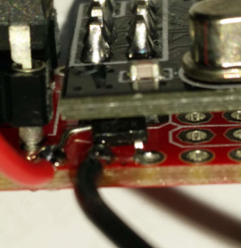
Currently this is my favorite board. Minimal size, traditional components and just enough breadboard space. A few variations:
Soldered an 8 mHz resonator (a 'crystal' which does not need the capacitors) for a more stable clock.
Soldered a 3.3v LDO (662k) under the radio to have it powered with a rechargeable Lipo (4.1V max) battery. And added a voltage divider to measure the actual battery voltage.
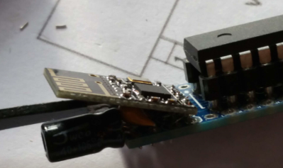
With a SMD version of the radio. Needs some creative soldering...Compared to an other favourite ( @GertSanders )
It would even be better if the smd radio could be soldered on the board. Kicad is giving me a headache so if anybody wants to volunteer with a panelized design.... (I will reward you with a free batch of 'dirty' boards, just drop me a pm)
-
AA batteries are 14mm in diameter. AAA batteries are 10mm in diameter.
I have single AAA batteryholders which are 13mm wide at the base, and including a battery they are 13mm high at the highest point.
LEGRAND sells 16x16mm cable ducts (http://www.ecataleg.be/fr/category/2751/16-x-16), which is what I plan to use, but the 15x15 ducts should work as well.
-
@GertSanders Good job! If you go the SMD way I think a lot could be done. Perhaps matching AAA width? Leave some (only few) SMD pads open for sensor connection, no proto area, etc.
@m26872 I'm trying to make a full SMD board with the smd variant of the nrf24.
So far, my first design is a 21mm square.
I have been thinking about a long 13mm x 100mm variant. That would allow plenty of space, at least 1 AAA, but more importantly would allow panelisation when combining with a 13x100 board for two AAA battery holders.
This would give 3 sensor nodes + 3 battery holder boards in one 100x100 panel, or 6 sensor boards if we use your technique of "ty-wrapping" batteries.
-
A couple of more questions. In one of the pictures at the top the electrulyte 4,.7 uf capacitator is placed closer to the atmel chip and the 0.1 uf (c5) is placed closest to the edge does it matter witch capacitator goes where?
The 10k resistor should be 1/4 or 1/8 W according to the bom. I had some small 1/6 W 10k resistors can I use them? I also have some bigger blue 10k resistor that I do not know the W rating on.
Where did you purchase the female pin-header that are used for the chips? I have some atmega chip-sockets that are quite narrow and it is hard to fit the components underneath. I also have some other female pin-headers but they are atleast twice as high than the ones in the pictures.
-
Currently this is my favorite board. Minimal size, traditional components and just enough breadboard space. A few variations:
With a SMD version of the radio. Needs some creative soldering...It would even be better if the smd radio could be soldered on the board. Kicad is giving me a headache so if anybody wants to volunteer with a panelized design.... (I will reward you with a free batch of 'dirty' boards, just drop me a pm)
@AWI said:
panelized design
If you're struggling with panelizing boards I can recommend the excellent gerber tools from Stijn Kuipers.
It allows you to create designs like this (10x10cm, DirtyPCBs):
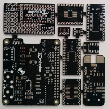
Drop him a message and he'll send you a download link.
http://yveaux.blogspot.nl
-
@AWI said:
panelized design
If you're struggling with panelizing boards I can recommend the excellent gerber tools from Stijn Kuipers.
It allows you to create designs like this (10x10cm, DirtyPCBs):
Drop him a message and he'll send you a download link.
-
@Yveaux Tnhx, but I guess I am not ready for the first step (creating/ adapting a board in Kicad) yet ....
-
@Yveaux I tried to find an email address on the website, but apart from a LinkIn link I could not find anything. Also, in LinkedIn you need a paying version to be able to send InMail, and I do not have a paid account. Would you care to tell me how you were able to send Stijn a message ?
-
A couple of more questions. In one of the pictures at the top the electrulyte 4,.7 uf capacitator is placed closer to the atmel chip and the 0.1 uf (c5) is placed closest to the edge does it matter witch capacitator goes where?
The 10k resistor should be 1/4 or 1/8 W according to the bom. I had some small 1/6 W 10k resistors can I use them? I also have some bigger blue 10k resistor that I do not know the W rating on.
Where did you purchase the female pin-header that are used for the chips? I have some atmega chip-sockets that are quite narrow and it is hard to fit the components underneath. I also have some other female pin-headers but they are atleast twice as high than the ones in the pictures.
@Cliff-Karlsson You can swap the capacitors and use all resistor dissipation values. The pin headers you can find here for example
-
@Yveaux I tried to find an email address on the website, but apart from a LinkIn link I could not find anything. Also, in LinkedIn you need a paying version to be able to send InMail, and I do not have a paid account. Would you care to tell me how you were able to send Stijn a message ?
@GertSanders It's been a while, but my first contact was through his Twitter account. Try that first, otherwise ping me.
http://yveaux.blogspot.nl
-
@GertSanders It's been a while, but my first contact was through his Twitter account. Try that first, otherwise ping me.
@Yveaux I do not have a twitter account, so no joy. And I feel stupid to say so, but how do you ping someone on this forum ?
-
@AWI said:
panelized design
If you're struggling with panelizing boards I can recommend the excellent gerber tools from Stijn Kuipers.
It allows you to create designs like this (10x10cm, DirtyPCBs):
Drop him a message and he'll send you a download link.
-
@Yveaux i remember once that i read that dirtypcbs does not allow for different designs in their panelized boards. Am i correct ?
-
@ahmedadelhosni apparently not :blush:
The board above was produced by ditypcb's. In fact they're one of the few (only?) cheap PCB manufacturers that allow panelization.@Yveaux aha. I thought that this means multiple (same) design not different. Thanks :)
-
Updated first post with share stats and info.
Feature requests and example links will come asap.
-
This post is deleted!
-
Hi
I've just ordered a set of the PCB boards and looking forward to putting these together mainly into reed switches and motion sensors
I have scanned the whole thread and there doesn't seem to be a comprehensive list of exactly which components are required anywhere here, well not all in one place at least.
Can I just confirm exactly what is required to build a senor node.
1 x PDB board
1 x ATMega328p 28pin PDIP
1 x NRF24L01+ radio module
1 x 4.7uF Decoupling-Capacitor for radio (I assume these are still required??)
1 x right angle pin header for connecting to program and connect batteries
1 x Length of cable ducting for housing
2 x AA batteries
Cables for connecting batteries
Battery connector
1 x senor of choice
I notice there seem to be an assortment of capacitors/regulators in most of the photos on this thread, but no definitive list of which are needed. (I am very new to all this so please excuse my ignorance)Extras needed
1 x FTDI USB to TTL Serial AdapterHave I missed anything of my list? Also I would be really grateful for links to some of the above components.
Sorry these are very basic noob questions, but I feel it would really helpful for people such as myself to have everything clearly listed in one place, as the main mysensors build pages do. So people know exactly what is needed.
-
@Matt-Pitts You can find a BOM for the board here:
https://www.openhardware.io/view/10/My-Slim-2AA-Battery-Node