Control lights and intencidad with Vera and arduino
-
Hello I would like to make the following project:
Control lights and intencidad with Vera and arduino. On, off and control its intencidad . It will be possible?
Can you help me with components and code?Thanks guys.
Forgive my English , I'm using google translate .
-
Hello I would like to make the following project:
Control lights and intencidad with Vera and arduino. On, off and control its intencidad . It will be possible?
Can you help me with components and code?Thanks guys.
Forgive my English , I'm using google translate .
@conde said:
Hello I would like to make the following project:
Control lights and intencidad with Vera and arduino. On, off and control its intencidad . It will be possible?
Can you help me with components and code?Thanks guys.
Forgive my English , I'm using google translate .
Conde
Yes you can do all of the above,turn lights on/off ,control Intensity and many more things. You didn't say whether you already own a Vera but if you do and you already have some light modules or appliance modules or switch modules then it is a matter of programming your Vera. If you don't have any modules then you will to have the
1....Vera
2... Serial or Ethernet gateway that you build yourself
3... Light dimmer you will build
4.. Outlet controller you will build
the list just depends upon your needs and imitation.
All of these builds are well documented on the Mysensor website.
So good luck and keep up the dreaming that is where all this stuff comes from someone having a need or a dream or both. -
Hello. Thanks for reply.
This is my first project witn arduino. I'm learning. xD
For this project i have:- the vera edge;
- arduino uno;
- NRF24L01+ 2.4GHz Wireless Transceiver;
- Relays;
So my question is. It's possible wiht this components? I need another?
You say: (All of these builds are well documented on the Mysensor website.) - can you please send me de link? because i can't found.
Thank you.
-
You should use an Arduino Nano for the Vera gateway as it has a hard time recognising the Uno board.
http://www.mysensors.org/build/serial_gateway
and
-
You should use an Arduino Nano for the Vera gateway as it has a hard time recognising the Uno board.
http://www.mysensors.org/build/serial_gateway
and
@hek said:
You should use an Arduino Nano for the Vera gateway as it has a hard time recognising the Uno board.
http://www.mysensors.org/build/serial_gateway
and
Are you sure?
An edge is running ui7 and then a serial gateway will not work. I had one running fine on my VeraLite until I 'upgraded' it to ui7. I never got it working until I built an Ethernet gateway.
Did this with an uno with 5100 shield. Runs perfectly, still hate ui7 though... -
Have a vague memory they got this fixed in a FW update... Haven't heard any problems from UI7 users lately... so I just assumed it wasn't a problem any more.
-
-
Hello. Thanks for reply.
This is my first project witn arduino. I'm learning. xD
For this project i have:- the vera edge;
- arduino uno;
- NRF24L01+ 2.4GHz Wireless Transceiver;
- Relays;
So my question is. It's possible wiht this components? I need another?
You say: (All of these builds are well documented on the Mysensor website.) - can you please send me de link? because i can't found.
Thank you.
@conde said:
Hello. Thanks for reply.
This is my first project witn arduino. I'm learning. xD
For this project i have:- the vera edge;
- arduino uno;
- NRF24L01+ 2.4GHz Wireless Transceiver;
- Relays;
So my question is. It's possible wiht this components? I need another?
You say: (All of these builds are well documented on the Mysensor website.) - can you please send me de link? because i can't found.
Thank you.
Conde
Here is an Example of a battery Operated wireless door sensor it uses a 18560 li-ion battery for power.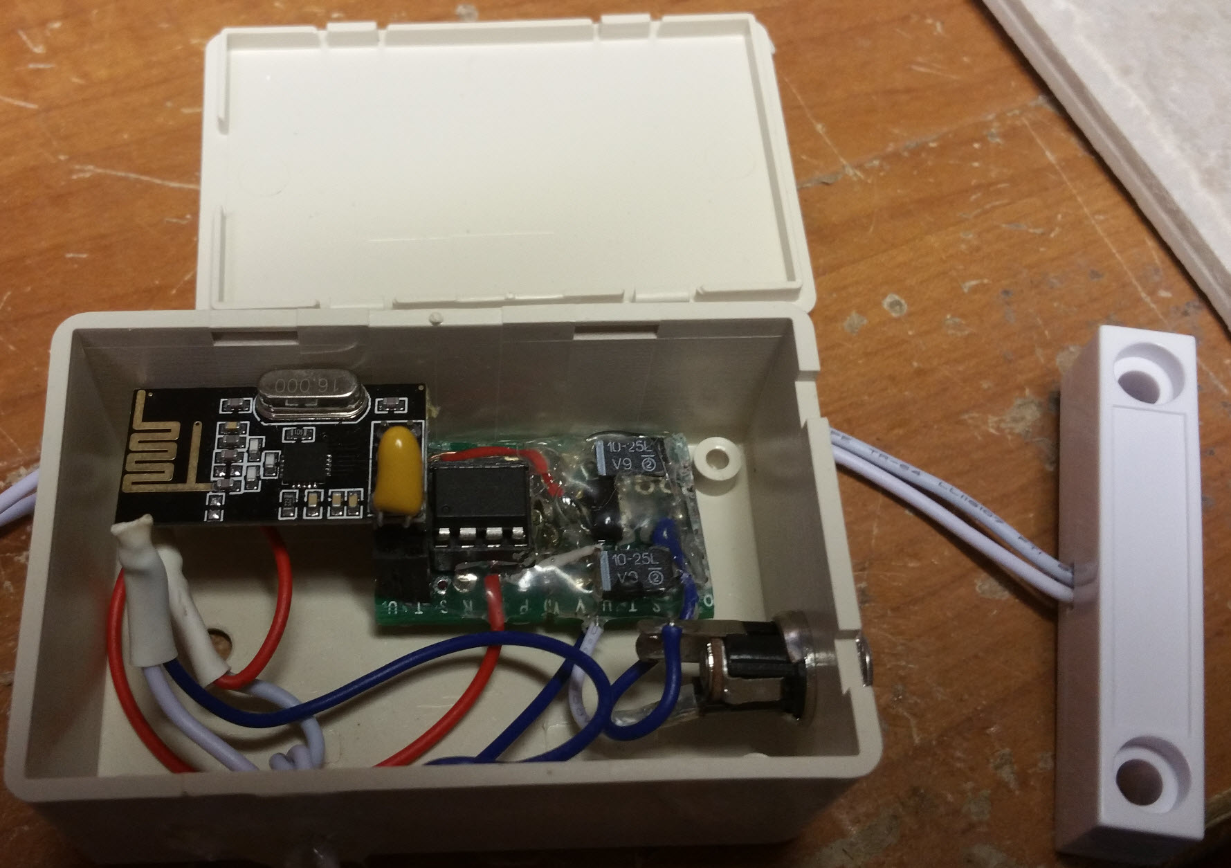
The project cost me about $8-$10.00 to build you might find parts cheaper or have some of your own but this uses a nRF24l01= transceiver and an ATtiny 85 mcu ,2- 22ufd caps a 3.3 volts LDO regulator.
If interested I can supply BOM and sketch. -
/ MySensorsDoor/Window sensor // Based on Attiny85 // Author: Wiebe Nieuwenhuis // these are suggested wire colors but you can use any color you want, just be consistent on all sensors // +-\/-+ // ORANGE CE 1|o |8 VCC RED // YELLOW CSN 2| |7 SCK GREEN // - SENSOR 3| |6 MOSI BLUE // BLACK GND 4| |5 MISO VIOLET // +----+ #include <MySensor.h> #include <Bounce2.h> #define SENSOR_INFO "Door sensor" #define NODE_ID 1 // Start numbering by 1 adding 1 each time you upload to new attiny85 #define CHILD_ID 1 // this number must match above number #define INPUT_PIN 4 // This is ATiny input number pin # 3 is the physical pin MySensor gw; Bounce debouncer = Bounce(); int oldValue = -1; MyMessage msg(NODE_ID, V_TRIPPED); void setup() { pinMode(INPUT_PIN, INPUT); digitalWrite(INPUT_PIN, HIGH); debouncer.attach(INPUT_PIN); debouncer.interval(5); gw.begin(NULL, NODE_ID, false, 0); gw.sendSketchInfo(SENSOR_INFO, "1.15"); gw.present(CHILD_ID, S_DOOR); } void loop() { debouncer.update(); int value = debouncer.read(); if (value != oldValue) { gw.send(msg.set(value==HIGH ? 1 : 0)); oldValue = value; } }- BOM
2cm x 8cm fiber glass perf board such as http://www.ebay.com/itm/10pcs-2X8-Double-side-Protoboard-Circuit-Universal-DIY-Prototype-PCB-Board-/111345609084?hash=item19ecb7297c
each board can make 4 sensors
1- AMS1117 3.3 v LDO regulator for each sensor, such as http://www.ebay.com/itm/10Pcs-National-Semiconductor-LM1117-3-3-LM1117-3-3V-LDO-SOT223-Voltage-Regulator-/281790082194?hash=item419bff6c92
2-10mfd 16v tantalum caps 3 for each sensor such as http://www.ebay.com/itm/50PCS-TANTALUM-CAPACITOR-10UF-16V-SMD-3216-NEW-/400985284440?hash=item5d5c95df58
1-ATtiny 85 chip for each sensor you build
1-8 pin socket if you wish to make it plug in but can be soldered in directly after you program chip.
1-nRF24l01+ transceiver for each sensor you build
1-5pin header female dbl row connector such as http://www.ebay.com/itm/50pcs-2-54mm-Pitch-2X5-10Pin-Female-Double-Row-Straight-Header-PCB-Connector-287-/171275351990?hash=item27e0ce77b6
or a 4 pin dbl row header connector will do also
1- case to fit your project
1-18650 LI-ION 4000 Mah battery and holder if you wish to power in this manner but can be powered by 5vdc 500 Mah phone charger type P.S.
Now there are other ways of doing this project but I found this works very well for me. There are people on this site that can do it more efficiently than the way I am showing here.
Good luck with your project and if I can help more just ask.Now plan well , have all of your materials on hand,research anything you are not sure of almost all the answers for any questions you have on the ATiny 85 are on the this site.
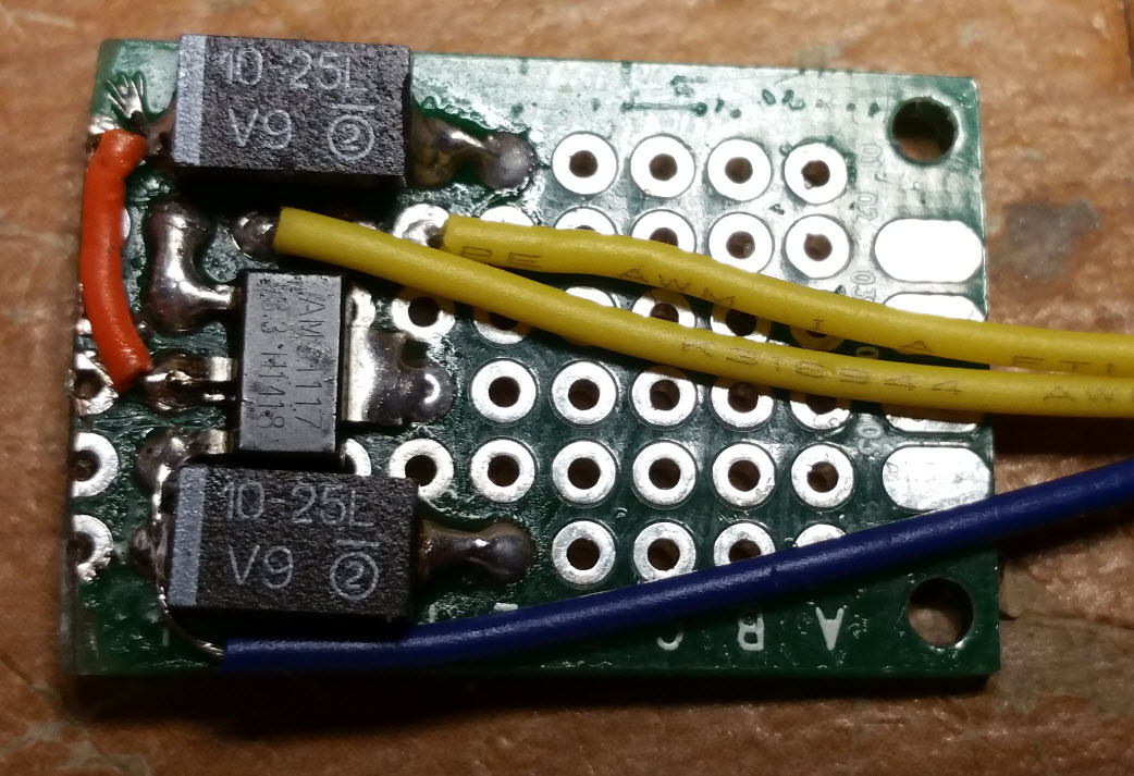
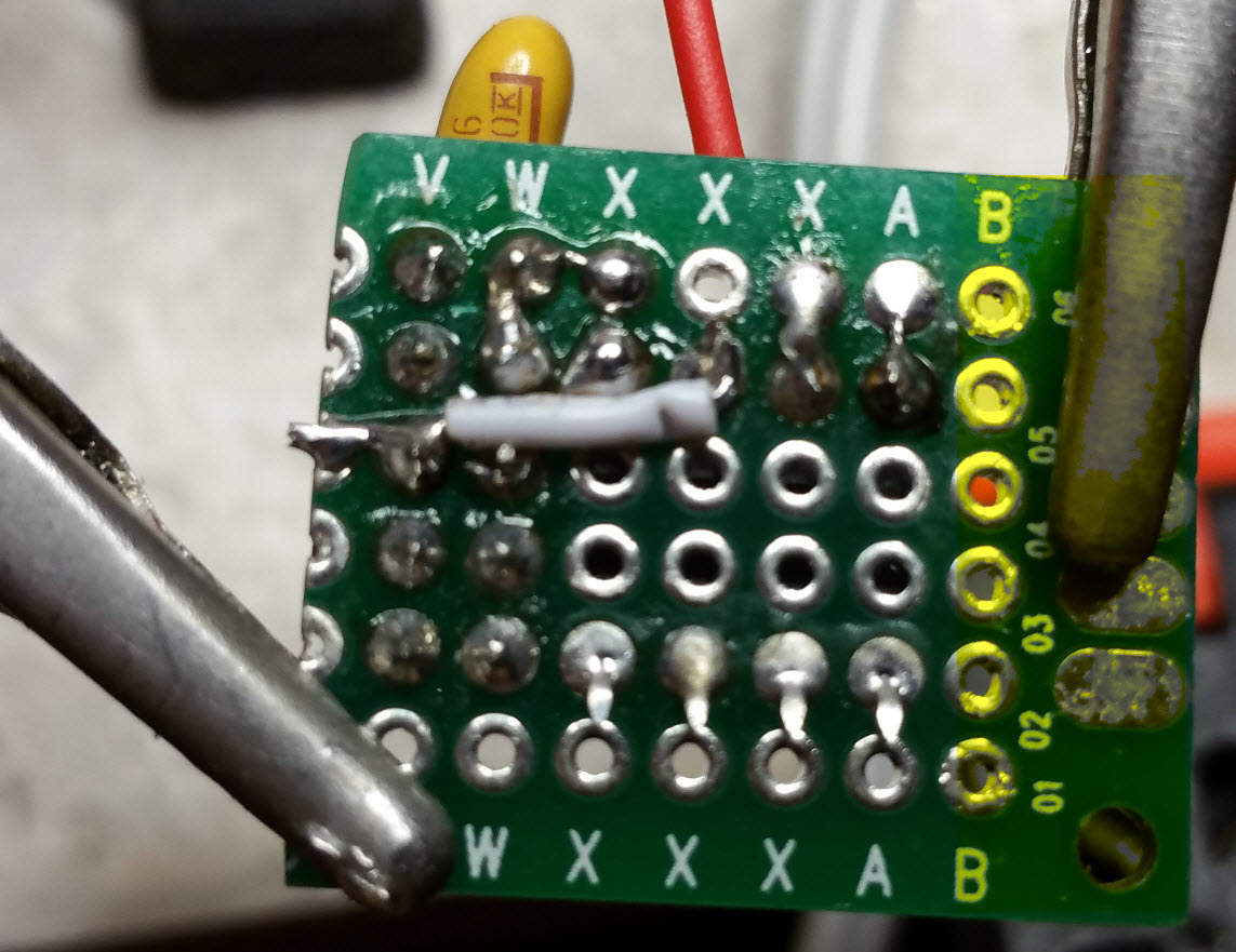
Now you will need a steady hand when soldering the SMD, be patient and be safe with the project .
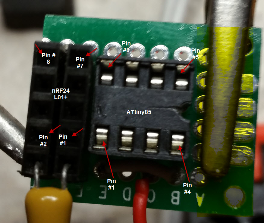
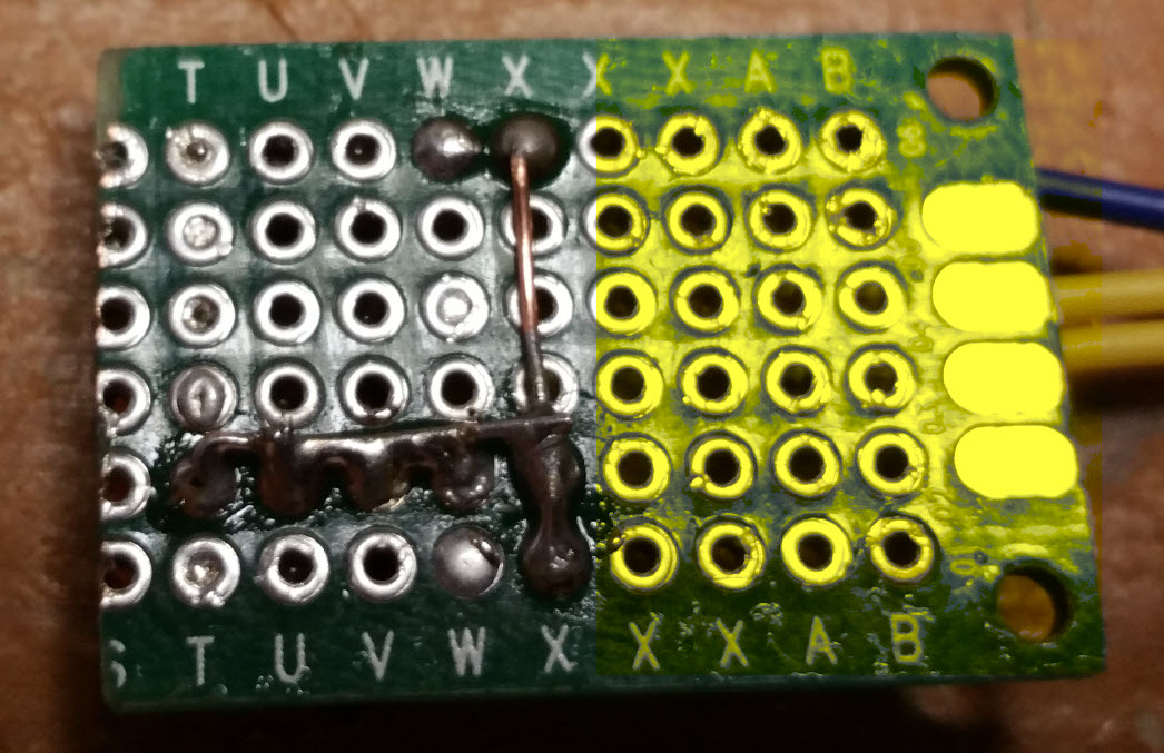
I will post a picture of the boards I am wiring. If you use sockets for the ATiny make sure you know where pin 1 is located the sockets are usually maked with a semi circle in the socket but you can put them in any way you choose if you know exactly where pin 1 is located. Same with the nRF24l01= 5 pin or 4 pin just make sure you know where pin 1 is located.
- BOM
-
/ MySensorsDoor/Window sensor // Based on Attiny85 // Author: Wiebe Nieuwenhuis // these are suggested wire colors but you can use any color you want, just be consistent on all sensors // +-\/-+ // ORANGE CE 1|o |8 VCC RED // YELLOW CSN 2| |7 SCK GREEN // - SENSOR 3| |6 MOSI BLUE // BLACK GND 4| |5 MISO VIOLET // +----+ #include <MySensor.h> #include <Bounce2.h> #define SENSOR_INFO "Door sensor" #define NODE_ID 1 // Start numbering by 1 adding 1 each time you upload to new attiny85 #define CHILD_ID 1 // this number must match above number #define INPUT_PIN 4 // This is ATiny input number pin # 3 is the physical pin MySensor gw; Bounce debouncer = Bounce(); int oldValue = -1; MyMessage msg(NODE_ID, V_TRIPPED); void setup() { pinMode(INPUT_PIN, INPUT); digitalWrite(INPUT_PIN, HIGH); debouncer.attach(INPUT_PIN); debouncer.interval(5); gw.begin(NULL, NODE_ID, false, 0); gw.sendSketchInfo(SENSOR_INFO, "1.15"); gw.present(CHILD_ID, S_DOOR); } void loop() { debouncer.update(); int value = debouncer.read(); if (value != oldValue) { gw.send(msg.set(value==HIGH ? 1 : 0)); oldValue = value; } }- BOM
2cm x 8cm fiber glass perf board such as http://www.ebay.com/itm/10pcs-2X8-Double-side-Protoboard-Circuit-Universal-DIY-Prototype-PCB-Board-/111345609084?hash=item19ecb7297c
each board can make 4 sensors
1- AMS1117 3.3 v LDO regulator for each sensor, such as http://www.ebay.com/itm/10Pcs-National-Semiconductor-LM1117-3-3-LM1117-3-3V-LDO-SOT223-Voltage-Regulator-/281790082194?hash=item419bff6c92
2-10mfd 16v tantalum caps 3 for each sensor such as http://www.ebay.com/itm/50PCS-TANTALUM-CAPACITOR-10UF-16V-SMD-3216-NEW-/400985284440?hash=item5d5c95df58
1-ATtiny 85 chip for each sensor you build
1-8 pin socket if you wish to make it plug in but can be soldered in directly after you program chip.
1-nRF24l01+ transceiver for each sensor you build
1-5pin header female dbl row connector such as http://www.ebay.com/itm/50pcs-2-54mm-Pitch-2X5-10Pin-Female-Double-Row-Straight-Header-PCB-Connector-287-/171275351990?hash=item27e0ce77b6
or a 4 pin dbl row header connector will do also
1- case to fit your project
1-18650 LI-ION 4000 Mah battery and holder if you wish to power in this manner but can be powered by 5vdc 500 Mah phone charger type P.S.
Now there are other ways of doing this project but I found this works very well for me. There are people on this site that can do it more efficiently than the way I am showing here.
Good luck with your project and if I can help more just ask.Now plan well , have all of your materials on hand,research anything you are not sure of almost all the answers for any questions you have on the ATiny 85 are on the this site.
Now you will need a steady hand when soldering the SMD, be patient and be safe with the project .
I will post a picture of the boards I am wiring. If you use sockets for the ATiny make sure you know where pin 1 is located the sockets are usually maked with a semi circle in the socket but you can put them in any way you choose if you know exactly where pin 1 is located. Same with the nRF24l01= 5 pin or 4 pin just make sure you know where pin 1 is located.
@mntlvr said:
/ MySensorsDoor/Window sensor // Based on Attiny85 // Revision 9/28/15 by BW // Author: Wiebe Nieuwenhuis // these are suggested wire colors but you can use any color you want, just be consistent on all sensors // +-\/-+ // ORANGE CE 1|o |8 VCC RED // YELLOW CSN 2| |7 SCK GREEN // - SENSOR 3| |6 MOSI BLUE // BLACK GND 4| |5 MISO VIOLET // +----+ #include <MySensor.h> #include <Bounce2.h> #define SENSOR_INFO "Door sensor" #define NODE_ID 1 // Start numbering by 1 adding 1 each time you upload to new attiny85 #define CHILD_ID 1 // this number must match above number #define INPUT_PIN 4 // This is ATiny input number pin # 3 is the physical pin MySensor gw; Bounce debouncer = Bounce(); int oldValue = -1; MyMessage msg(NODE_ID, V_TRIPPED); void setup() { pinMode(INPUT_PIN, INPUT); digitalWrite(INPUT_PIN, HIGH); debouncer.attach(INPUT_PIN); debouncer.interval(5); gw.begin(NULL, NODE_ID, false, 0); gw.sendSketchInfo(SENSOR_INFO, "1.15"); gw.present(CHILD_ID, S_DOOR); } void loop() { debouncer.update(); int value = debouncer.read(); if (value != oldValue) { gw.send(msg.set(value==HIGH ? 1 : 0)); oldValue = value; } }- BOM
2cm x 8cm fiber glass perf board such as http://www.ebay.com/itm/10pcs-2X8-Double-side-Protoboard-Circuit-Universal-DIY-Prototype-PCB-Board-/111345609084?hash=item19ecb7297c
each board can make 4 sensors
1- AMS1117 3.3 v LDO regulator for each sensor, such as http://www.ebay.com/itm/10Pcs-National-Semiconductor-LM1117-3-3-LM1117-3-3V-LDO-SOT223-Voltage-Regulator-/281790082194?hash=item419bff6c92
2-10mfd 16v tantalum caps 3 for each sensor such as http://www.ebay.com/itm/50PCS-TANTALUM-CAPACITOR-10UF-16V-SMD-3216-NEW-/400985284440?hash=item5d5c95df58
1-ATtiny 85 chip for each sensor you build
1-8 pin socket if you wish to make it plug in but can be soldered in directly after you program chip.
1-nRF24l01+ transceiver for each sensor you build
1-5pin header female dbl row connector such as http://www.ebay.com/itm/50pcs-2-54mm-Pitch-2X5-10Pin-Female-Double-Row-Straight-Header-PCB-Connector-287-/171275351990?hash=item27e0ce77b6
or a 4 pin dbl row header connector will do also
1- case to fit your project
1-18650 LI-ION 4000 Mah battery and holder if you wish to power in this manner but can be powered by 5vdc 500 Mah phone charger type P.S.
Now there are other ways of doing this project but I found this works very well for me. There are people on this site that can do it more efficiently than the way I am showing here.
Good luck with your project and if I can help more just ask.Now plan well , have all of your materials on hand,research anything you are not sure of almost all the answers for any questions you have on the ATiny 85 are on the this site.
Now you will need a steady hand when soldering the SMD, be patient and be safe with the project .
I will post a picture of the boards I am wiring. If you use sockets for the ATtiny make sure you know where pin 1 is located the sockets are usually marked with a semi circle in the socket but you can put them in any way you choose if you know exactly where pin 1 is located. Same with the nRF24l01= 5 pin or 4 pin just make sure you know where pin 1 is located.
Now if you eliminate the 3.3v regulator and run your Attiny off of just the battery you will save about 20ma. Now you will have to place a 1n4007 diode in series with the batteries + terminal and the sensors + input wire, having the cathode of the diode going to the battery +
I am still working on a way to power down the nRF24l01+ transceiver. I have asked the members on this site for some help with this project..
now I do power my units with a 5 vdc phone charger so right now I have to leave the 3.3 vdc regulator in the circuit.
I also have modified the original sketch to put the Attiny85 to sleep for 2 to 4 sec. You would not what the door switch being left unmonitored for more time than that. Now I may also change this to use a pin change to immediately wake unit.
Here is the code I am running as of now.* * Watchdog Sleep * Modified on 5 Feb 2011 by InsideGadgets (www.insidegadgets.com) * to suit the ATtiny85 and removed the cbi( MCUCR,SE ) section * in setup() to match the Atmel datasheet recommendations */ #include <avr/sleep.h> #include <avr/wdt.h> #include <MySensor.h> #include <Bounce2.h> #ifndef cbi #define cbi(sfr, bit) (_SFR_BYTE(sfr) &= ~_BV(bit)) #endif #ifndef sbi #define sbi(sfr, bit) (_SFR_BYTE(sfr) |= _BV(bit)) #endif #define SENSOR_INFO "Door sensor" #define NODE_ID 14 // Start numbering by 1 adding 1 each time you upload to new attiny85 #define CHILD_ID 14 // this number must match above number #define INPUT_PIN 4 // int pinLed = 0; volatile boolean f_wdt = 1; MySensor gw; Bounce debouncer = Bounce(); int oldValue = -1; MyMessage msg(NODE_ID, V_TRIPPED); void setup(){ pinMode(INPUT_PIN, INPUT); digitalWrite(INPUT_PIN, HIGH); setup_watchdog(8); // approximately 4 seconds sleep debouncer.attach(INPUT_PIN); debouncer.interval(5); gw.begin(NULL, NODE_ID, false, 0); gw.sendSketchInfo(SENSOR_INFO, "1.15"); gw.present(CHILD_ID, S_DOOR); } void loop(){ if (f_wdt==1) { // wait for timed out watchdog / flag is set when a watchdog timeout occurs f_wdt=0; // reset flag debouncer.update(); int value = debouncer.read(); if (value != oldValue) { gw.send(msg.set(value==HIGH ? 1 : 0)); oldValue = value; system_sleep(); } } } // set system into the sleep state // system wakes up when wtchdog is timed out void system_sleep() { cbi(ADCSRA,ADEN); // switch Analog to Digitalconverter OFF set_sleep_mode(SLEEP_MODE_PWR_DOWN); // sleep mode is set here sleep_enable(); sleep_mode(); // System sleeps here sleep_disable(); // System continues execution here when watchdog timed out sbi(ADCSRA,ADEN); // switch Analog to Digitalconverter ON } // 0=16ms, 1=32ms,2=64ms,3=128ms,4=250ms,5=500ms // 6=1 sec,7=2 sec, 8=4 sec, 9= 8sec void setup_watchdog(int ii) { byte bb; int ww; if (ii > 9 ) ii=9; bb=ii & 7; if (ii > 7) bb|= (1<<5); bb|= (1<<WDCE); ww=bb; MCUSR &= ~(1<<WDRF); // start timed sequence WDTCR |= (1<<WDCE) | (1<<WDE); // set new watchdog timeout value WDTCR = bb; WDTCR |= _BV(WDIE); } // Watchdog Interrupt Service / is executed when watchdog timed out ISR(WDT_vect) { f_wdt=1; // set global flag }``` - BOM
-
@mntlvr said:
/ MySensorsDoor/Window sensor // Based on Attiny85 // Revision 9/28/15 by BW // Author: Wiebe Nieuwenhuis // these are suggested wire colors but you can use any color you want, just be consistent on all sensors // +-\/-+ // ORANGE CE 1|o |8 VCC RED // YELLOW CSN 2| |7 SCK GREEN // - SENSOR 3| |6 MOSI BLUE // BLACK GND 4| |5 MISO VIOLET // +----+ #include <MySensor.h> #include <Bounce2.h> #define SENSOR_INFO "Door sensor" #define NODE_ID 1 // Start numbering by 1 adding 1 each time you upload to new attiny85 #define CHILD_ID 1 // this number must match above number #define INPUT_PIN 4 // This is ATiny input number pin # 3 is the physical pin MySensor gw; Bounce debouncer = Bounce(); int oldValue = -1; MyMessage msg(NODE_ID, V_TRIPPED); void setup() { pinMode(INPUT_PIN, INPUT); digitalWrite(INPUT_PIN, HIGH); debouncer.attach(INPUT_PIN); debouncer.interval(5); gw.begin(NULL, NODE_ID, false, 0); gw.sendSketchInfo(SENSOR_INFO, "1.15"); gw.present(CHILD_ID, S_DOOR); } void loop() { debouncer.update(); int value = debouncer.read(); if (value != oldValue) { gw.send(msg.set(value==HIGH ? 1 : 0)); oldValue = value; } }- BOM
2cm x 8cm fiber glass perf board such as http://www.ebay.com/itm/10pcs-2X8-Double-side-Protoboard-Circuit-Universal-DIY-Prototype-PCB-Board-/111345609084?hash=item19ecb7297c
each board can make 4 sensors
1- AMS1117 3.3 v LDO regulator for each sensor, such as http://www.ebay.com/itm/10Pcs-National-Semiconductor-LM1117-3-3-LM1117-3-3V-LDO-SOT223-Voltage-Regulator-/281790082194?hash=item419bff6c92
2-10mfd 16v tantalum caps 3 for each sensor such as http://www.ebay.com/itm/50PCS-TANTALUM-CAPACITOR-10UF-16V-SMD-3216-NEW-/400985284440?hash=item5d5c95df58
1-ATtiny 85 chip for each sensor you build
1-8 pin socket if you wish to make it plug in but can be soldered in directly after you program chip.
1-nRF24l01+ transceiver for each sensor you build
1-5pin header female dbl row connector such as http://www.ebay.com/itm/50pcs-2-54mm-Pitch-2X5-10Pin-Female-Double-Row-Straight-Header-PCB-Connector-287-/171275351990?hash=item27e0ce77b6
or a 4 pin dbl row header connector will do also
1- case to fit your project
1-18650 LI-ION 4000 Mah battery and holder if you wish to power in this manner but can be powered by 5vdc 500 Mah phone charger type P.S.
Now there are other ways of doing this project but I found this works very well for me. There are people on this site that can do it more efficiently than the way I am showing here.
Good luck with your project and if I can help more just ask.Now plan well , have all of your materials on hand,research anything you are not sure of almost all the answers for any questions you have on the ATiny 85 are on the this site.
Now you will need a steady hand when soldering the SMD, be patient and be safe with the project .
I will post a picture of the boards I am wiring. If you use sockets for the ATtiny make sure you know where pin 1 is located the sockets are usually marked with a semi circle in the socket but you can put them in any way you choose if you know exactly where pin 1 is located. Same with the nRF24l01= 5 pin or 4 pin just make sure you know where pin 1 is located.
Now if you eliminate the 3.3v regulator and run your Attiny off of just the battery you will save about 20ma. Now you will have to place a 1n4007 diode in series with the batteries + terminal and the sensors + input wire, having the cathode of the diode going to the battery +
I am still working on a way to power down the nRF24l01+ transceiver. I have asked the members on this site for some help with this project..
now I do power my units with a 5 vdc phone charger so right now I have to leave the 3.3 vdc regulator in the circuit.
I also have modified the original sketch to put the Attiny85 to sleep for 2 to 4 sec. You would not what the door switch being left unmonitored for more time than that. Now I may also change this to use a pin change to immediately wake unit.
Here is the code I am running as of now.* * Watchdog Sleep * Modified on 5 Feb 2011 by InsideGadgets (www.insidegadgets.com) * to suit the ATtiny85 and removed the cbi( MCUCR,SE ) section * in setup() to match the Atmel datasheet recommendations */ #include <avr/sleep.h> #include <avr/wdt.h> #include <MySensor.h> #include <Bounce2.h> #ifndef cbi #define cbi(sfr, bit) (_SFR_BYTE(sfr) &= ~_BV(bit)) #endif #ifndef sbi #define sbi(sfr, bit) (_SFR_BYTE(sfr) |= _BV(bit)) #endif #define SENSOR_INFO "Door sensor" #define NODE_ID 14 // Start numbering by 1 adding 1 each time you upload to new attiny85 #define CHILD_ID 14 // this number must match above number #define INPUT_PIN 4 // int pinLed = 0; volatile boolean f_wdt = 1; MySensor gw; Bounce debouncer = Bounce(); int oldValue = -1; MyMessage msg(NODE_ID, V_TRIPPED); void setup(){ pinMode(INPUT_PIN, INPUT); digitalWrite(INPUT_PIN, HIGH); setup_watchdog(8); // approximately 4 seconds sleep debouncer.attach(INPUT_PIN); debouncer.interval(5); gw.begin(NULL, NODE_ID, false, 0); gw.sendSketchInfo(SENSOR_INFO, "1.15"); gw.present(CHILD_ID, S_DOOR); } void loop(){ if (f_wdt==1) { // wait for timed out watchdog / flag is set when a watchdog timeout occurs f_wdt=0; // reset flag debouncer.update(); int value = debouncer.read(); if (value != oldValue) { gw.send(msg.set(value==HIGH ? 1 : 0)); oldValue = value; system_sleep(); } } } // set system into the sleep state // system wakes up when wtchdog is timed out void system_sleep() { cbi(ADCSRA,ADEN); // switch Analog to Digitalconverter OFF set_sleep_mode(SLEEP_MODE_PWR_DOWN); // sleep mode is set here sleep_enable(); sleep_mode(); // System sleeps here sleep_disable(); // System continues execution here when watchdog timed out sbi(ADCSRA,ADEN); // switch Analog to Digitalconverter ON } // 0=16ms, 1=32ms,2=64ms,3=128ms,4=250ms,5=500ms // 6=1 sec,7=2 sec, 8=4 sec, 9= 8sec void setup_watchdog(int ii) { byte bb; int ww; if (ii > 9 ) ii=9; bb=ii & 7; if (ii > 7) bb|= (1<<5); bb|= (1<<WDCE); ww=bb; MCUSR &= ~(1<<WDRF); // start timed sequence WDTCR |= (1<<WDCE) | (1<<WDE); // set new watchdog timeout value WDTCR = bb; WDTCR |= _BV(WDIE); } // Watchdog Interrupt Service / is executed when watchdog timed out ISR(WDT_vect) { f_wdt=1; // set global flag }```@mntlvr I'm excited to see that mysensors is working with attiny. However, when I compile your code for UNO (can't compile for attiny85 on my IDE), I see the code is about 16kb, much larger than the size of the available memory in attiny85. Did you use a different library?
- BOM
-
@mntlvr I'm excited to see that mysensors is working with attiny. However, when I compile your code for UNO (can't compile for attiny85 on my IDE), I see the code is about 16kb, much larger than the size of the available memory in attiny85. Did you use a different library?
@ted said:
@mntlvr I'm excited to see that mysensors is working with attiny. However, when I compile your code for UNO (can't compile for attiny85 on my IDE), I see the code is about 16kb, much larger than the size of the available memory in attiny85. Did you use a different library?
Yes a mysensor library written for the Attiny85 chip. And also remember you need to either make a Attiny85 programmer or buy one. I think the 1st choice is the best. There are many articles on the Web that will guide you on how to build your own peogrammer. So do a little research and you will be greatly rewarded. Patience and perseverance will get you what you need and want.
Hello! It looks like you're interested in this conversation, but you don't have an account yet.
Getting fed up of having to scroll through the same posts each visit? When you register for an account, you'll always come back to exactly where you were before, and choose to be notified of new replies (either via email, or push notification). You'll also be able to save bookmarks and upvote posts to show your appreciation to other community members.
With your input, this post could be even better 💗
Register Login