Skip to content
  • MySensors
  • OpenHardware.io
  • Categories
  • Recent
  • Tags
  • Popular
Skins
  • Light
  • Brite
  • Cerulean
  • Cosmo
  • Flatly
  • Journal
  • Litera
  • Lumen
  • Lux
  • Materia
  • Minty
  • Morph
  • Pulse
  • Sandstone
  • Simplex
  • Sketchy
  • Spacelab
  • United
  • Yeti
  • Zephyr
  • Dark
  • Cyborg
  • Darkly
  • Quartz
  • Slate
  • Solar
  • Superhero
  • Vapor

  • Default (No Skin)
  • No Skin
Collapse
Brand Logo
  1. Home
  2. My Project
  3. Multisensor node using Ceech board

Multisensor node using Ceech board

Scheduled Pinned Locked Moved My Project
64 Posts 8 Posters 28.4k Views 11 Watching
  • Oldest to Newest
  • Newest to Oldest
  • Most Votes
Reply
  • Reply as topic
Log in to reply
This topic has been deleted. Only users with topic management privileges can see it.
  • joaoabsJ Offline
    joaoabsJ Offline
    joaoabs
    wrote on last edited by
    #7

    Great stuff!

    I'll test it during the weekend!

    Thanks!

    1 Reply Last reply
    0
    • joaoabsJ Offline
      joaoabsJ Offline
      joaoabs
      wrote on last edited by joaoabs
      #8

      Hi,

      It works great! Thanks!
      Did you tune the potentiometers, or left as they were?

      I'm using 2x 6v, 100mA solar panels in parallel and one 5000mAh Li-ion battery.

      EDIT:
      Now in a sunny day, it seems something is missing (probably some tuning in the potentiometers). Somehow the battery is not charging:

      Batt: 3.73V ; 1.30mA 
      Solar: 6.64V ; 0.00 mA; charge: No
      BattPct: 33% 
      send: 19-19-0-0 s=10,c=1,t=38,pt=7,l=5,st=ok:3.732
      send: 19-19-0-0 s=10,c=1,t=39,pt=7,l=5,st=ok:1.298047
      send: 19-19-0-0 s=11,c=1,t=38,pt=7,l=5,st=ok:6.640
      send: 19-19-0-0 s=11,c=1,t=39,pt=7,l=5,st=ok:0.000000
      send: 19-19-0-0 s=255,c=3,t=0,pt=1,l=1,st=ok:33
      

      ceech.jpg

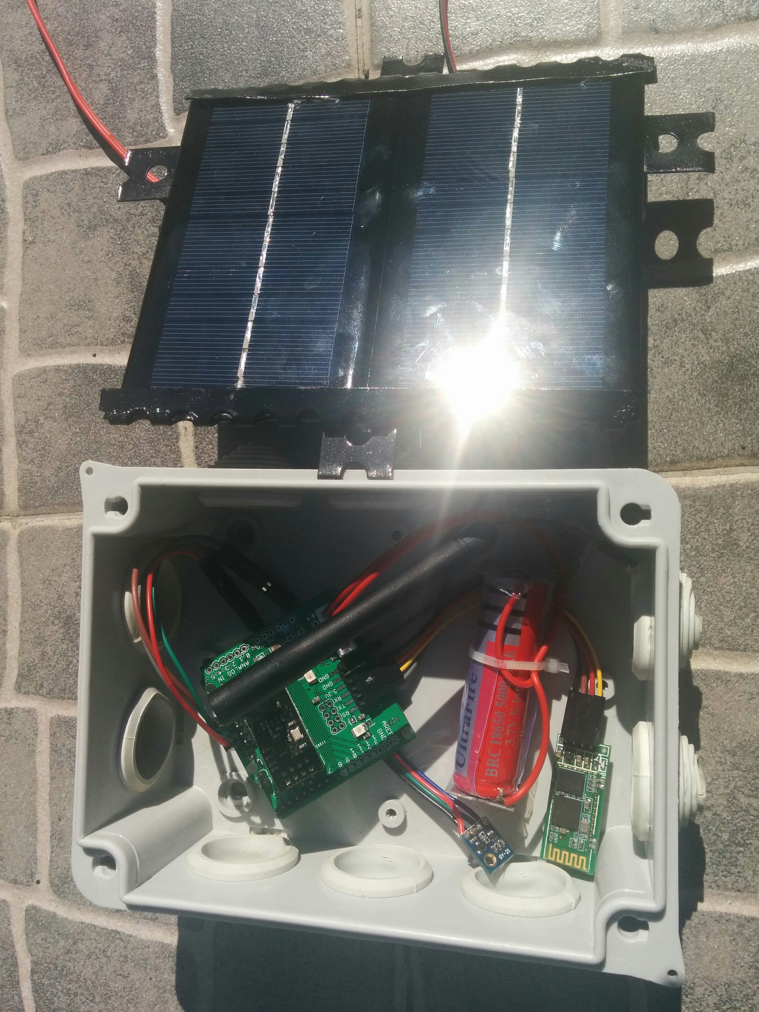
      Any idea/suggestion?

      Thanks!
      Joao

      1 Reply Last reply
      0
      • M Offline
        M Offline
        MikeF
        wrote on last edited by
        #9

        @joaoabs Glad you got it working.

        No, I didn't tune the pots.

        I had similar problems with solar panels: battery didn't seem to be charging. Also, you're getting a high solar voltage (6.64V) on a sunny day, as I did. I was concerned, as the absolute max Vin for the LTC4067 - from the datasheet, if I remember correctly - is 6.2V.

        I gave up using solar cells, and I'll just charge the battery from a USB charger when I need to.

        1 Reply Last reply
        0
        • joaoabsJ Offline
          joaoabsJ Offline
          joaoabs
          wrote on last edited by
          #10

          Thanks for the feedback.

          I think the key here is in the potentiomenters, so I looked around for some guidance:

          The two trimmer potentiometers are used to determine the current for both the input side - to better match the internal resistance of the solar cell - and for the battery charge current. At shipping they are both set to around half the value ( 2.5kOhm), which set both currents to about 75mA.
          

          I don't know how to measure the internal resistance of the solar cell (shouldn't be as simple as measuring it with a ohmmeter, right?), but I'm assuming that if 75mA is half the value, the maximum should be 150mA. Since my panels in parallel can supply (theoretically) up to 200mA, I'll rotate the potentiomenter to its maximum. Now, wich potentiomenter is it (not identified in the board), and what to tune in the other potentiometer (should be the same mA, what does it depend on)?

          @Ceech, Any guidance on how to overcome this not-charging problem?

          Thanks,
          Joao

          C 1 Reply Last reply
          0
          • joaoabsJ joaoabs

            Thanks for the feedback.

            I think the key here is in the potentiomenters, so I looked around for some guidance:

            The two trimmer potentiometers are used to determine the current for both the input side - to better match the internal resistance of the solar cell - and for the battery charge current. At shipping they are both set to around half the value ( 2.5kOhm), which set both currents to about 75mA.
            

            I don't know how to measure the internal resistance of the solar cell (shouldn't be as simple as measuring it with a ohmmeter, right?), but I'm assuming that if 75mA is half the value, the maximum should be 150mA. Since my panels in parallel can supply (theoretically) up to 200mA, I'll rotate the potentiomenter to its maximum. Now, wich potentiomenter is it (not identified in the board), and what to tune in the other potentiometer (should be the same mA, what does it depend on)?

            @Ceech, Any guidance on how to overcome this not-charging problem?

            Thanks,
            Joao

            C Offline
            C Offline
            ceech
            Hardware Contributor
            wrote on last edited by
            #11

            @joaoabs Try lowering input voltage. The IC is in overvoltage mode and we don't want to damage it. Next, try with 5V input. See if you get the charge.
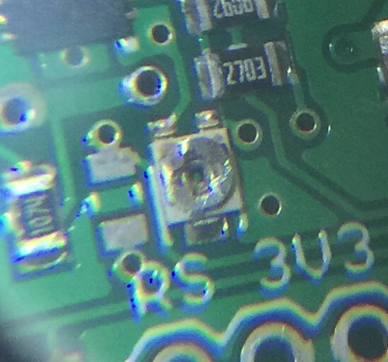
            The trimmer potentiometers:
            03_trimmer_pot.png
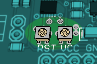
            The left one is battery charge current limit. Turn it to the left in order to maximize charging current.
            And the right one is input current limit. Keep the input current below solar panel maximum current. Turn it left to increase current limit.

            This is a formula to calculate input current: Ilim = 200V/Rclprog , where Rclprog stands for trimmer resistance.
            And this is how you calculate charging current: Ich = 1000V/Rprog, where Rprog stands for trimmer resistance. It is also limited with input current.

            1 Reply Last reply
            0
            • M Offline
              M Offline
              MikeF
              wrote on last edited by
              #12

              @ceech I'm using a more recent version of this board, with an LTC4079 charger (instead of the LTC4067).

              Which Arduino pin is the ~CHRG signal brought out on? A2 appears to be Vin (solar cell), whereas if I do analogRead(A7) I get a value around 500 (regardless of whether Vin is connected or not)?

              1 Reply Last reply
              0
              • C Offline
                C Offline
                ceech
                Hardware Contributor
                wrote on last edited by
                #13

                ~CHRG is at ADC A7. It pulls low when the battery is getting charged. It's not always zero, sometimes is stuck around 10 or below. It works in conjunction with ADC A6, which is a battery current pin. Do you get any reports here?

                1 Reply Last reply
                0
                • M Offline
                  M Offline
                  MikeF
                  wrote on last edited by
                  #14

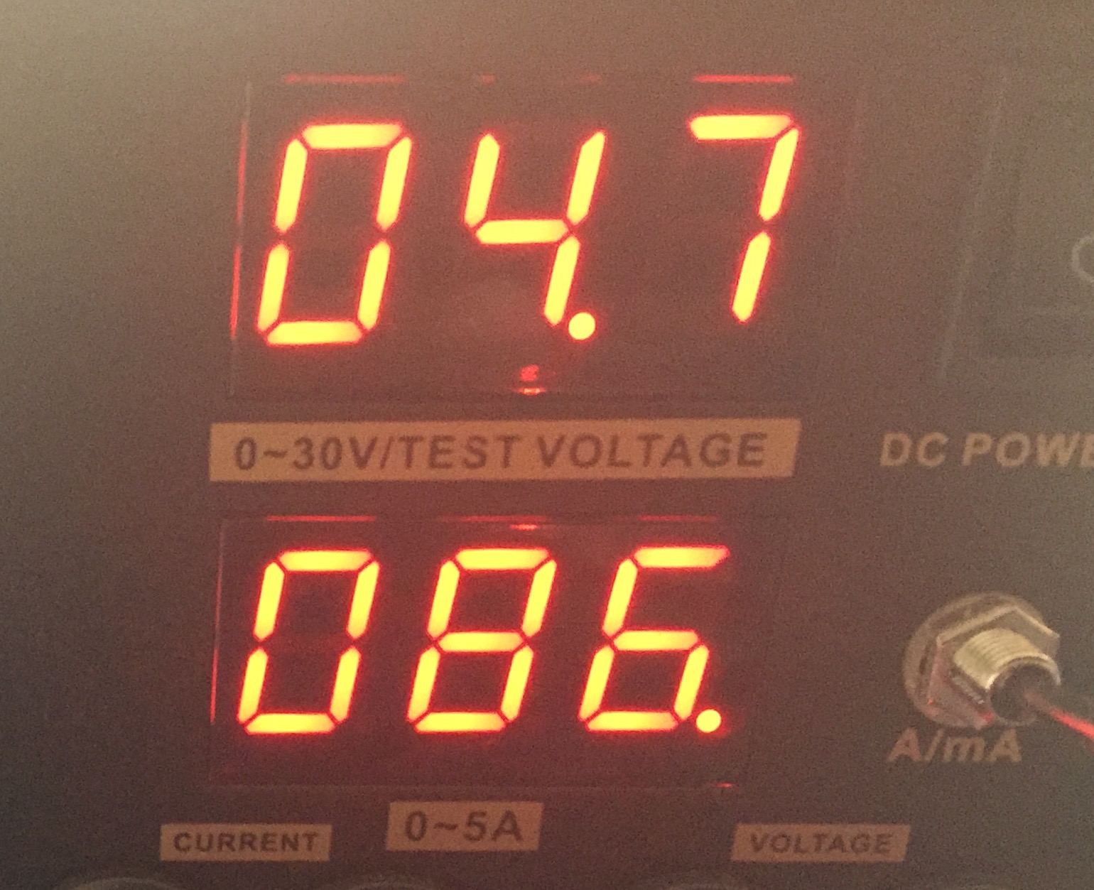
                  @ceech I've connected a 5V USB supply to the solar cell input, and I'm running your example sketch from your eBay web page for this board. I'm seeing a battery voltage of 3.59V (Li-ion), and charge current (monitoring A6) of 0.00mA - suggesting the battery isn't charging? As said before, A7 is showing values around 479.

                  Vcc = 3.30V
                  Charge current = 0.00mA
                  Solar cell voltage = 4.98V
                  Battery voltage = 3.59V
                  CHRG = 479

                  1 Reply Last reply
                  0
                  • C Offline
                    C Offline
                    ceech
                    Hardware Contributor
                    wrote on last edited by
                    #15

                    Ah, yes. I think i know what the problem is. The LTC4079 has a built-in MPPT power tracking for solar panels and won't charge if the input voltage is below set point. This helps optimizing power extraction from solar panels. If you are using 5V input, then you should adjust the trimmer pot on the board. Like this
                    0_1464367270031_hiijeejj.jpg
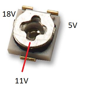
                    Turn the top round part of the trimmer to the left so that the wiper reaches 5V mark like on the above picture. In other words reduce trimmer resistance to minimum. The other way around is for 18V solar panels.

                    1 Reply Last reply
                    1
                    • M Offline
                      M Offline
                      MikeF
                      wrote on last edited by
                      #16

                      @ceech That did it - thanks! :smile:

                      Currently charging at c. 90mA:

                      Vcc = 3.30V
                      Charge current = 89.93mA
                      Solar cell voltage = 4.95V
                      Battery voltage = 3.62V
                      CHRG = 0

                      1 Reply Last reply
                      0
                      • alexsh1A Offline
                        alexsh1A Offline
                        alexsh1
                        wrote on last edited by alexsh1
                        #17

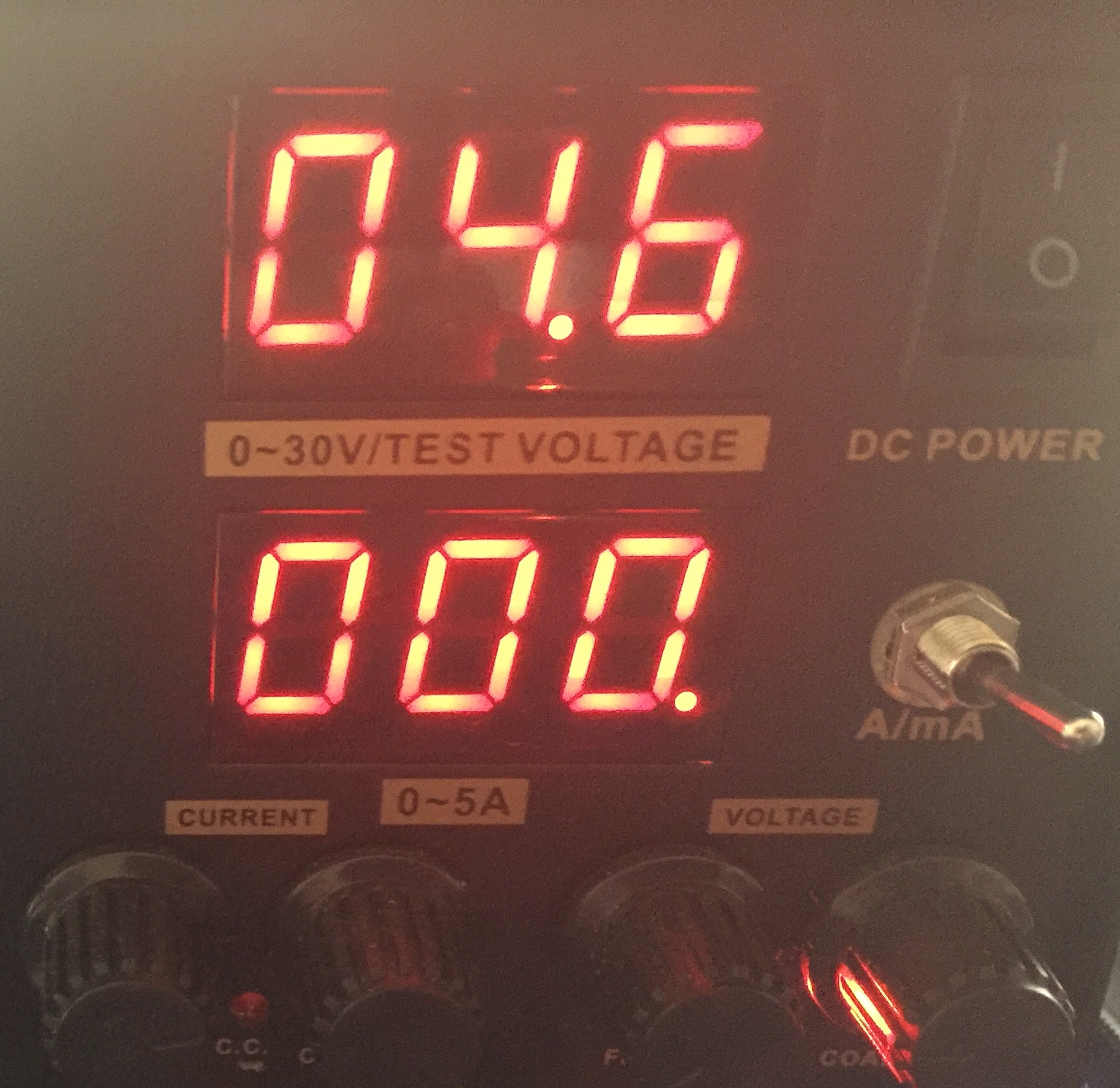
                        @ceech I have the same problem with the LTC4079 board:

                        Running a simplified sketch gives the following:

                        Vcc = 3.39V
                        Charge current = 2.26mA
                        Solar cell voltage = 5.40V
                        Battery voltage = 4.11V
                        CHRG = 502
                        
                        
                        Vcc = 3.42V
                        Charge current = 0.25mA
                        Solar cell voltage = 5.41V
                        Battery voltage = 4.11V
                        CHRG = 500
                        
                        Vcc = 3.35V
                        Charge current = 0.00mA
                        Solar cell voltage = 5.24V
                        Battery voltage = 4.11V
                        CHRG = 498
                        
                        Vcc = 3.33V
                        Charge current = 0.00mA
                        Solar cell voltage = 5.19V
                        Battery voltage = 4.08V
                        CHRG = 496
                        

                        CHRG is never goes to zero or close and the charging current is low or zero. Shall I try to adjust the same potentiometer as above?

                        1 Reply Last reply
                        0
                        • C Offline
                          C Offline
                          ceech
                          Hardware Contributor
                          wrote on last edited by
                          #18

                          If the trimmer is in the same position as when new, then yes. Turn it anti-clockwise to reach its minimum value. Either that or raise the input voltage to 11V.

                          alexsh1A 1 Reply Last reply
                          0
                          • C ceech

                            If the trimmer is in the same position as when new, then yes. Turn it anti-clockwise to reach its minimum value. Either that or raise the input voltage to 11V.

                            alexsh1A Offline
                            alexsh1A Offline
                            alexsh1
                            wrote on last edited by
                            #19

                            @ceech I cannot supply more than 6V as this is my solar panel maximum voltage.

                            How many turns or degrees shall turn it?
                            I did one and a half turn, but it still does not charge the battery. This is the current position.

                            0_1464621473404_image.jpeg

                            1 Reply Last reply
                            0
                            • C Offline
                              C Offline
                              ceech
                              Hardware Contributor
                              wrote on last edited by ceech
                              #20

                              This is a one turn trimmer. Its minimum value is close to 5V mark on one of the above pictures. And its maximum value is next to 18V mark. Since you've turned it more than once, you have to first determine the current wiper position. If you look closely you can see that the turning top is not quite round. One side is a bit flattened. That is the opposite side of the wiper. Now if you take a look at your picture then I think your wiper position is at around 6 or 7V ( to use the same terminology). I would say 20 more degrees to the left and you'll reach 5V.

                              You can also measure the trimmer's resistance. Like so
                              0_1464622721379_42262818.jpg
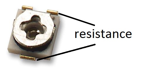
                              Find the minimum value between marked points. That is your target resistance value.

                              1 Reply Last reply
                              0
                              • alexsh1A Offline
                                alexsh1A Offline
                                alexsh1
                                wrote on last edited by alexsh1
                                #21

                                @ceech - many thanks for above.
                                I think I nailed it finally.
                                Is the voltage below normal or can that be adjusted somehow?

                                Vcc = 3.35V
                                Charge current = 34.22mA
                                Solar cell voltage = 4.55V
                                Battery voltage = 3.80V
                                CHRG = 446
                                
                                
                                Vcc = 3.39V
                                Charge current = 31.87mA
                                Solar cell voltage = 4.72V
                                Battery voltage = 3.78V
                                CHRG = 451
                                

                                When does analogue A7 (CHRG) go down to zero or around zero?

                                1 Reply Last reply
                                0
                                • C Offline
                                  C Offline
                                  ceech
                                  Hardware Contributor
                                  wrote on last edited by
                                  #22

                                  What voltage would you like to adjust?
                                  The current is a bit low. What is your panel's maximum available current?
                                  The charger is not operating at its full power. Either you are a bit high with the setting on the trimmer or the panel can't supply enough. Charging current should be around 90mA.

                                  1 Reply Last reply
                                  0
                                  • alexsh1A Offline
                                    alexsh1A Offline
                                    alexsh1
                                    wrote on last edited by alexsh1
                                    #23

                                    @ceech The solar panal is 6V 4.5W, but right now it is used inside under my table lamp hence a lower voltage (4.7V). I'll to put it in the sun once the weather improves to test it.

                                    EDIT: I have not tested the solar panel before in the sun. Obviously, it provides ~4.8V inside and not sure if it will provide closer to 6v in the sun. I purchased it here http://www.ebay.co.uk/itm/281945297221

                                    Can I connect 5.5v power supply to the 'solar cell' contacts from a reliable PSU to test the trimmer settings ?

                                    alexsh1A 1 Reply Last reply
                                    0
                                    • alexsh1A alexsh1

                                      @ceech The solar panal is 6V 4.5W, but right now it is used inside under my table lamp hence a lower voltage (4.7V). I'll to put it in the sun once the weather improves to test it.

                                      EDIT: I have not tested the solar panel before in the sun. Obviously, it provides ~4.8V inside and not sure if it will provide closer to 6v in the sun. I purchased it here http://www.ebay.co.uk/itm/281945297221

                                      Can I connect 5.5v power supply to the 'solar cell' contacts from a reliable PSU to test the trimmer settings ?

                                      alexsh1A Offline
                                      alexsh1A Offline
                                      alexsh1
                                      wrote on last edited by
                                      #24

                                      @ceech

                                      Ok, it looks like the trimmer is set to 5.5-6V
                                      I am feeding it from 5.5V PSU instead of the solar panal

                                      Charge current = 92.28mA
                                      Solar cell voltage = 5.54V
                                      Battery voltage = 3.82V
                                      CHRG = 467
                                      
                                      
                                      1 Reply Last reply
                                      0
                                      • C Offline
                                        C Offline
                                        ceech
                                        Hardware Contributor
                                        wrote on last edited by ceech
                                        #25

                                        Sure use your power supply. No problem. If the solar cell is 6V, than leave the trimmer. I think you got it just right.
                                        And you were getting 30mA INDOORS? That's great. I'm quite pleased with that information.
                                        This means that this sensor board can also be used as Indoors solar harvester.

                                        1 Reply Last reply
                                        0
                                        • alexsh1A Offline
                                          alexsh1A Offline
                                          alexsh1
                                          wrote on last edited by
                                          #26

                                          @ceech yes, 30ma indoor, but it is under a direct light. The cut-off voltage is around 4.7V for charging.

                                          1_1464625903597_image.jpeg 0_1464625903596_image.jpeg

                                          C 1 Reply Last reply
                                          0
                                          Reply
                                          • Reply as topic
                                          Log in to reply
                                          • Oldest to Newest
                                          • Newest to Oldest
                                          • Most Votes


                                          22

                                          Online

                                          11.7k

                                          Users

                                          11.2k

                                          Topics

                                          113.1k

                                          Posts


                                          Copyright 2025 TBD   |   Forum Guidelines   |   Privacy Policy   |   Terms of Service
                                          • Login

                                          • Don't have an account? Register

                                          • Login or register to search.
                                          • First post
                                            Last post
                                          0
                                          • MySensors
                                          • OpenHardware.io
                                          • Categories
                                          • Recent
                                          • Tags
                                          • Popular