Skip to content
  • MySensors
  • OpenHardware.io
  • Categories
  • Recent
  • Tags
  • Popular
Skins
  • Light
  • Brite
  • Cerulean
  • Cosmo
  • Flatly
  • Journal
  • Litera
  • Lumen
  • Lux
  • Materia
  • Minty
  • Morph
  • Pulse
  • Sandstone
  • Simplex
  • Sketchy
  • Spacelab
  • United
  • Yeti
  • Zephyr
  • Dark
  • Cyborg
  • Darkly
  • Quartz
  • Slate
  • Solar
  • Superhero
  • Vapor

  • Default (No Skin)
  • No Skin
Collapse
Brand Logo
  1. Home
  2. My Project
  3. Multisensor node using Ceech board

Multisensor node using Ceech board

Scheduled Pinned Locked Moved My Project
64 Posts 8 Posters 28.4k Views 11 Watching
  • Oldest to Newest
  • Newest to Oldest
  • Most Votes
Reply
  • Reply as topic
Log in to reply
This topic has been deleted. Only users with topic management privileges can see it.
  • rollercontainerR Offline
    rollercontainerR Offline
    rollercontainer
    wrote on last edited by
    #36

    Thank you very much!

    The 1180 ohm value was found in the IoT_pro_04.sch file at https://www.openhardware.io/view/44/Solar-powered-sensor-board#tabs-design. Or isnt it the resistance value? Maybe a smd size?

    1 Reply Last reply
    0
    • C Offline
      C Offline
      ceech
      Hardware Contributor
      wrote on last edited by
      #37

      SMD size of the resistor is 0805.

      1 Reply Last reply
      0
      • rollercontainerR Offline
        rollercontainerR Offline
        rollercontainer
        wrote on last edited by
        #38

        As I understood, there is a buck boost converter that lifts the battery voltage to 3,3V. So I thought, two 1,5V batteries would be sufficient. Am I wrong?

        I've got a 5V solar panel and turned the trimmer clockwise to the end. Correct? (tried counterclockwise also, nothing changed.)

        Vcc = 2.96V
        Charge current = 0.00mA
        Solar cell voltage = 4.89V
        Battery voltage = 2.79V
        CHRG = 0
        
        1 Reply Last reply
        0
        • rollercontainerR Offline
          rollercontainerR Offline
          rollercontainer
          wrote on last edited by
          #39

          I've got light a bit closer and a current showed up:

          Vcc = 3.01V
          Charge current = 2.23mA
          Solar cell voltage = 4.89V
          Battery voltage = 2.85V
          CHRG = 0
          

          Is Vcc messuring the voltage comming from the usb device?

          1 Reply Last reply
          0
          • C Offline
            C Offline
            ceech
            Hardware Contributor
            wrote on last edited by ceech
            #40

            There are two versions of the board. One with a voltage regulator and one with a buck-boost converter. The first one does not step-up the voltage and the other does.
            Here is how the trimmer potentiometer work:
            0_1469951800535_hiijeejj.jpg
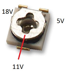
            The viper is on the red line. Turn it counterclockwise till it reaches the 5V mark. This is a 5V setting.
            5V solar cell is fine, just remember that the minimum voltage for the charger to operate is 4.75V. You are already on the minimum, so the solar cell needs to be well lit in order for system to operate.
            Vcc is a voltage rail that powers the microcontroller. It measures its own voltage.
            If you already have the solar cell and the battery connected than the USB voltage must not be applied!

            1 Reply Last reply
            0
            • rollercontainerR Offline
              rollercontainerR Offline
              rollercontainer
              wrote on last edited by
              #41

              In the ebay auction I bought it your text says buck boost converter. On the chip there is a number gnq 666 601, but I cant find him. Board says: 77534K_Y471

              1 Reply Last reply
              0
              • C Offline
                C Offline
                ceech
                Hardware Contributor
                wrote on last edited by
                #42

                The first number from IC is the LTC4079. Board number means that you have one with a voltage regulator. You somehow ended with one. You can send it back and I'll send you replacement if you wish.

                1 Reply Last reply
                0
                • rollercontainerR Offline
                  rollercontainerR Offline
                  rollercontainer
                  wrote on last edited by
                  #43

                  I am not amused...

                  I will buy additonal batteries and a second solar cell.

                  1 Reply Last reply
                  0
                  • C Offline
                    C Offline
                    ceech
                    Hardware Contributor
                    wrote on last edited by
                    #44

                    There are also the appropriate charging voltage and current settings to be made to accommodate for the NiCd batteries. Are you sure you don't want for me to do it for you?

                    1 Reply Last reply
                    0
                    • rollercontainerR Offline
                      rollercontainerR Offline
                      rollercontainer
                      wrote on last edited by
                      #45

                      I thought, sunset will be enough to terminate charging on NiCd?

                      So its easier to take 3,2V LiFePo4, right? And because my board only regulates down, I have to take 2 in series to provide enough voltage to regulate, right?

                      All these flat LiPo types provide ~3,7V. Is that enough to feed the regulator (+dropout)?

                      1 Reply Last reply
                      0
                      • C Offline
                        C Offline
                        ceech
                        Hardware Contributor
                        wrote on last edited by ceech
                        #46

                        Proper voltage and current also take effect in charging NiCd batteries.
                        And LiFePO4 would also require different charge voltage (3.6V).
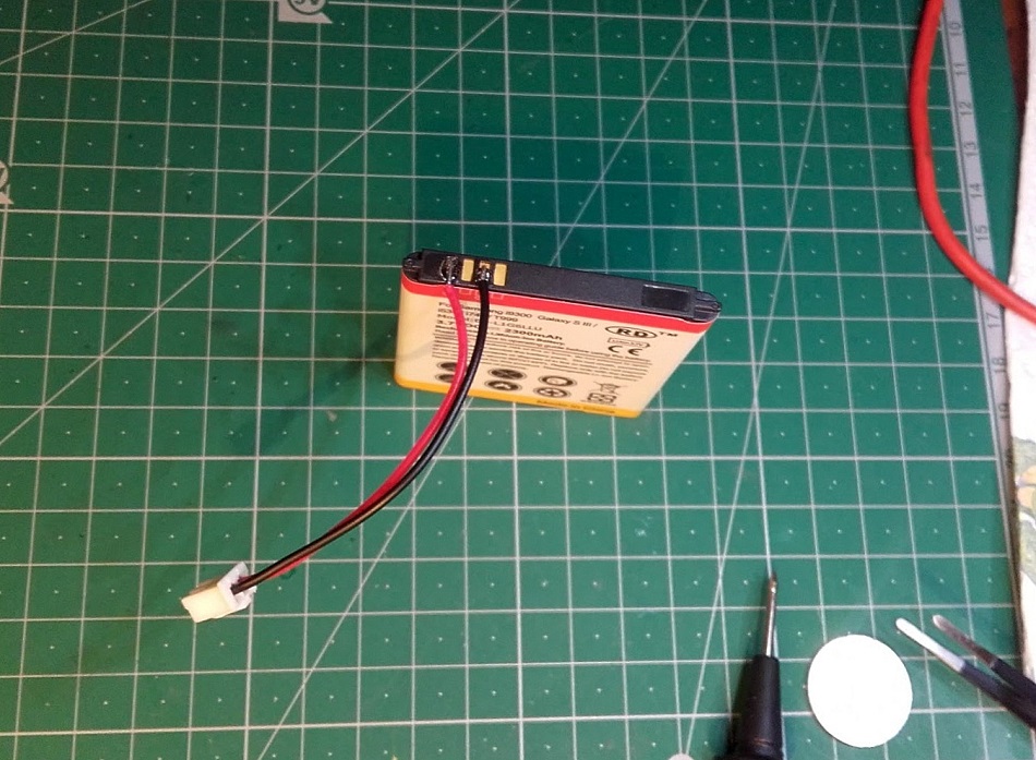
                        The best option is a single cell LiPo battery with a capacity between 1000mAh and 2500mAh.
                        Charge voltage matches (4.2V) and the current as well. Voltage regulator on the board is extremely efficient with just 2uA of consumption and 180mV dropout voltage. At 3V with the battery you still get 2.82V for the microcontroller. That's plenty. And quiescent current is the same in dropout. You'll be well off.

                        1 Reply Last reply
                        0
                        • rollercontainerR Offline
                          rollercontainerR Offline
                          rollercontainer
                          wrote on last edited by
                          #47

                          like this one?
                          http://www.ebay.de/itm/1x-Lipo-Akku-LxBxH-75-x-40-x-5-6-mm-3-7V-2000mAh-1S-JST-Stecker-554475-/371581598136

                          1 Reply Last reply
                          0
                          • C Offline
                            C Offline
                            ceech
                            Hardware Contributor
                            wrote on last edited by
                            #48

                            Like that one, yes. Or, if you do not mind doing some soldering yourself, you can choose one from this list:
                            http://www.ebay.com/sch/i.html?_from=R40&_sacat=0&_nkw=Li-ion+Replacement+Battery+For+Samsung&_sop=15

                            I do it like this:
                            0_1470041071125_20160801_103631.jpg

                            1 Reply Last reply
                            0
                            • rollercontainerR Offline
                              rollercontainerR Offline
                              rollercontainer
                              wrote on last edited by
                              #49

                              I wanted to use it outside for collecting weather data. But the battery which the board is designed for isn't suitable for temperatures below 0°C.

                              Is that right so far?

                              Or did you successfully used Li-Ion outside below 0°C?

                              1 Reply Last reply
                              0
                              • C Offline
                                C Offline
                                ceech
                                Hardware Contributor
                                wrote on last edited by
                                #50

                                The capacity of LiPo batteries start to decline below 0 degrees Celsius. But that is a fact in all kinds of batteries. You are not going to notice much change till below -20 degrees. I found this post which describes it perfectly ( scroll down a little ):
                                https://backpackinglight.com/forums/topic/84570/

                                1 Reply Last reply
                                0
                                • rollercontainerR Offline
                                  rollercontainerR Offline
                                  rollercontainer
                                  wrote on last edited by
                                  #51

                                  Ok, now I've got a 12V 50mA solar cell and a 3,7V 2000mAh LiPo. Potentiometer is at 12 o'clock (flat segment at the single solder pad)

                                  Can you please try to explain what exactly the potentiometer is adjusting?
                                  Does the charger only charge if the cell voltage is below the adjusted voltage level?

                                  Your example sketch is not showing any charging current:

                                  Vcc = 3.32V
                                  Charge current = 0.00mA
                                  Solar cell voltage = 0.24V
                                  Battery voltage = 3.79V
                                  CHRG = 424
                                  
                                  Vcc = 3.32V
                                  Charge current = 0.00mA
                                  Solar cell voltage = 7.44V
                                  Battery voltage = 3.79V
                                  CHRG = 409
                                  
                                  Vcc = 3.32V
                                  Charge current = 0.00mA
                                  Solar cell voltage = 11.72V
                                  Battery voltage = 3.79V
                                  CHRG = 0
                                  
                                  alexsh1A C 2 Replies Last reply
                                  0
                                  • rollercontainerR rollercontainer

                                    Ok, now I've got a 12V 50mA solar cell and a 3,7V 2000mAh LiPo. Potentiometer is at 12 o'clock (flat segment at the single solder pad)

                                    Can you please try to explain what exactly the potentiometer is adjusting?
                                    Does the charger only charge if the cell voltage is below the adjusted voltage level?

                                    Your example sketch is not showing any charging current:

                                    Vcc = 3.32V
                                    Charge current = 0.00mA
                                    Solar cell voltage = 0.24V
                                    Battery voltage = 3.79V
                                    CHRG = 424
                                    
                                    Vcc = 3.32V
                                    Charge current = 0.00mA
                                    Solar cell voltage = 7.44V
                                    Battery voltage = 3.79V
                                    CHRG = 409
                                    
                                    Vcc = 3.32V
                                    Charge current = 0.00mA
                                    Solar cell voltage = 11.72V
                                    Battery voltage = 3.79V
                                    CHRG = 0
                                    
                                    alexsh1A Offline
                                    alexsh1A Offline
                                    alexsh1
                                    wrote on last edited by
                                    #52

                                    @rollercontainer I would suggest you scroll up and see a few posts above concerning your question. The setting for potentiometer- for you it should be around 6 o'clock (or 12 o'clock where the cut-off mark is).

                                    Basically what it does is adjusting when your battery is being charged. For example, I have a 5V solar panel and I'd like the LiPO to start being charged at 4.75V therefore I put the potentiometer at the minimum (around 2pm or 8pm cut-off mark). This threshold (in my case 4.75V) can be adjusted by this potentiometer.

                                    1 Reply Last reply
                                    0
                                    • rollercontainerR rollercontainer

                                      Ok, now I've got a 12V 50mA solar cell and a 3,7V 2000mAh LiPo. Potentiometer is at 12 o'clock (flat segment at the single solder pad)

                                      Can you please try to explain what exactly the potentiometer is adjusting?
                                      Does the charger only charge if the cell voltage is below the adjusted voltage level?

                                      Your example sketch is not showing any charging current:

                                      Vcc = 3.32V
                                      Charge current = 0.00mA
                                      Solar cell voltage = 0.24V
                                      Battery voltage = 3.79V
                                      CHRG = 424
                                      
                                      Vcc = 3.32V
                                      Charge current = 0.00mA
                                      Solar cell voltage = 7.44V
                                      Battery voltage = 3.79V
                                      CHRG = 409
                                      
                                      Vcc = 3.32V
                                      Charge current = 0.00mA
                                      Solar cell voltage = 11.72V
                                      Battery voltage = 3.79V
                                      CHRG = 0
                                      
                                      C Offline
                                      C Offline
                                      ceech
                                      Hardware Contributor
                                      wrote on last edited by
                                      #53

                                      @rollercontainer The potentiometer is adjusting the voltage at which the solar panel is operating at its maximum power. It is so called MPPT. Just set it to the solar panel's nominal voltage.
                                      When the voltage on the solar panel is reduced (is in shade or we want to extract too much from it), the charger reduces the charging current in order to prevent the solar panel from collapsing entirely.

                                      1 Reply Last reply
                                      0
                                      • rollercontainerR Offline
                                        rollercontainerR Offline
                                        rollercontainer
                                        wrote on last edited by
                                        #54

                                        D'oh! I thought, the wiper of the trimmer is at the flat side, but its opposite to the flat, got it finally. Now pimatic is showing a current (0.74A).

                                        1 Reply Last reply
                                        0
                                        • FraidF Offline
                                          FraidF Offline
                                          Fraid
                                          wrote on last edited by
                                          #55

                                          Hi everyone, I'm new to arduino, and I bougth Ceech board.
                                          Can someone please let me know how to upload sketch on this board? I read it's compatible with arduino but I can't find any wiring schema.
                                          Also where is A7/CHRG ? Because my board go from analog A0 to A5.
                                          And I bought the following one :
                                          http://www.ebay.com/itm/331838940273?_trksid=p2057872.m2749.l2649&ssPageName=STRK%3AMEBIDX%3AIT

                                          I just want a solar/battery powered sensor. And I have anduino nano.
                                          Thank

                                          alexsh1A 1 Reply Last reply
                                          0
                                          Reply
                                          • Reply as topic
                                          Log in to reply
                                          • Oldest to Newest
                                          • Newest to Oldest
                                          • Most Votes


                                          17

                                          Online

                                          11.7k

                                          Users

                                          11.2k

                                          Topics

                                          113.1k

                                          Posts


                                          Copyright 2025 TBD   |   Forum Guidelines   |   Privacy Policy   |   Terms of Service
                                          • Login

                                          • Don't have an account? Register

                                          • Login or register to search.
                                          • First post
                                            Last post
                                          0
                                          • MySensors
                                          • OpenHardware.io
                                          • Categories
                                          • Recent
                                          • Tags
                                          • Popular