Multisensor node using Ceech board
-
Proper voltage and current also take effect in charging NiCd batteries.
And LiFePO4 would also require different charge voltage (3.6V).
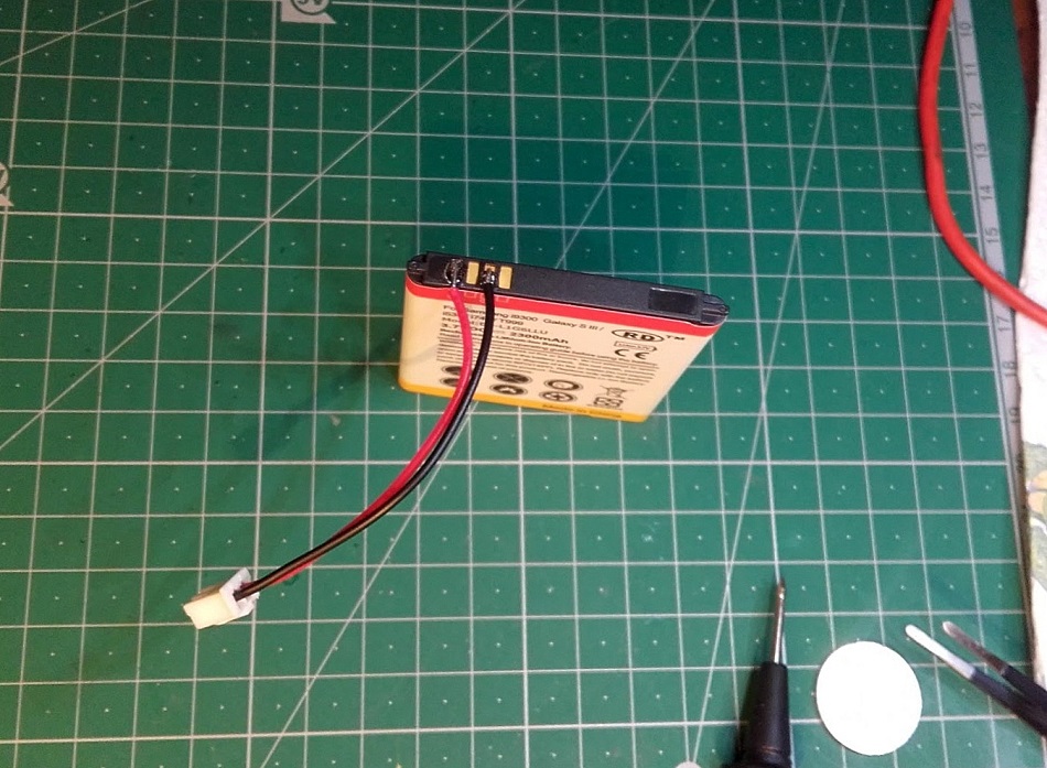
The best option is a single cell LiPo battery with a capacity between 1000mAh and 2500mAh.
Charge voltage matches (4.2V) and the current as well. Voltage regulator on the board is extremely efficient with just 2uA of consumption and 180mV dropout voltage. At 3V with the battery you still get 2.82V for the microcontroller. That's plenty. And quiescent current is the same in dropout. You'll be well off. -
-
Like that one, yes. Or, if you do not mind doing some soldering yourself, you can choose one from this list:
http://www.ebay.com/sch/i.html?_from=R40&_sacat=0&_nkw=Li-ion+Replacement+Battery+For+Samsung&_sop=15I do it like this:
-
I wanted to use it outside for collecting weather data. But the battery which the board is designed for isn't suitable for temperatures below 0°C.
Is that right so far?
Or did you successfully used Li-Ion outside below 0°C?
-
The capacity of LiPo batteries start to decline below 0 degrees Celsius. But that is a fact in all kinds of batteries. You are not going to notice much change till below -20 degrees. I found this post which describes it perfectly ( scroll down a little ):
https://backpackinglight.com/forums/topic/84570/ -
Ok, now I've got a 12V 50mA solar cell and a 3,7V 2000mAh LiPo. Potentiometer is at 12 o'clock (flat segment at the single solder pad)
Can you please try to explain what exactly the potentiometer is adjusting?
Does the charger only charge if the cell voltage is below the adjusted voltage level?Your example sketch is not showing any charging current:
Vcc = 3.32V
Charge current = 0.00mA
Solar cell voltage = 0.24V
Battery voltage = 3.79V
CHRG = 424
Vcc = 3.32V Charge current = 0.00mA Solar cell voltage = 7.44V Battery voltage = 3.79V CHRG = 409Vcc = 3.32V Charge current = 0.00mA Solar cell voltage = 11.72V Battery voltage = 3.79V CHRG = 0 -
Ok, now I've got a 12V 50mA solar cell and a 3,7V 2000mAh LiPo. Potentiometer is at 12 o'clock (flat segment at the single solder pad)
Can you please try to explain what exactly the potentiometer is adjusting?
Does the charger only charge if the cell voltage is below the adjusted voltage level?Your example sketch is not showing any charging current:
Vcc = 3.32V
Charge current = 0.00mA
Solar cell voltage = 0.24V
Battery voltage = 3.79V
CHRG = 424
Vcc = 3.32V Charge current = 0.00mA Solar cell voltage = 7.44V Battery voltage = 3.79V CHRG = 409Vcc = 3.32V Charge current = 0.00mA Solar cell voltage = 11.72V Battery voltage = 3.79V CHRG = 0@rollercontainer I would suggest you scroll up and see a few posts above concerning your question. The setting for potentiometer- for you it should be around 6 o'clock (or 12 o'clock where the cut-off mark is).
Basically what it does is adjusting when your battery is being charged. For example, I have a 5V solar panel and I'd like the LiPO to start being charged at 4.75V therefore I put the potentiometer at the minimum (around 2pm or 8pm cut-off mark). This threshold (in my case 4.75V) can be adjusted by this potentiometer.
-
Ok, now I've got a 12V 50mA solar cell and a 3,7V 2000mAh LiPo. Potentiometer is at 12 o'clock (flat segment at the single solder pad)
Can you please try to explain what exactly the potentiometer is adjusting?
Does the charger only charge if the cell voltage is below the adjusted voltage level?Your example sketch is not showing any charging current:
Vcc = 3.32V
Charge current = 0.00mA
Solar cell voltage = 0.24V
Battery voltage = 3.79V
CHRG = 424
Vcc = 3.32V Charge current = 0.00mA Solar cell voltage = 7.44V Battery voltage = 3.79V CHRG = 409Vcc = 3.32V Charge current = 0.00mA Solar cell voltage = 11.72V Battery voltage = 3.79V CHRG = 0@rollercontainer The potentiometer is adjusting the voltage at which the solar panel is operating at its maximum power. It is so called MPPT. Just set it to the solar panel's nominal voltage.
When the voltage on the solar panel is reduced (is in shade or we want to extract too much from it), the charger reduces the charging current in order to prevent the solar panel from collapsing entirely. -
D'oh! I thought, the wiper of the trimmer is at the flat side, but its opposite to the flat, got it finally. Now pimatic is showing a current (0.74A).
-
Hi everyone, I'm new to arduino, and I bougth Ceech board.
Can someone please let me know how to upload sketch on this board? I read it's compatible with arduino but I can't find any wiring schema.
Also where is A7/CHRG ? Because my board go from analog A0 to A5.
And I bought the following one :
http://www.ebay.com/itm/331838940273?_trksid=p2057872.m2749.l2649&ssPageName=STRK%3AMEBIDX%3AITI just want a solar/battery powered sensor. And I have anduino nano.
Thank -
Hi everyone, I'm new to arduino, and I bougth Ceech board.
Can someone please let me know how to upload sketch on this board? I read it's compatible with arduino but I can't find any wiring schema.
Also where is A7/CHRG ? Because my board go from analog A0 to A5.
And I bought the following one :
http://www.ebay.com/itm/331838940273?_trksid=p2057872.m2749.l2649&ssPageName=STRK%3AMEBIDX%3AITI just want a solar/battery powered sensor. And I have anduino nano.
Thank@Fraid-DIRON welcome to the forum! This is beginners question and I would suggest you browse www.arduino.cc
You will find tons of international on that web-site concerning programming Arduino in general. This is how I was learning it.Concerning Ceech's board, it is programmed the same way as any Arduino Pro or Arduino Pro Mini - with a help of FTDI USB to TTL converter (there are many on eBay) connected to the 6 angled pins on the board.
This link is for Pro Mini, but Pro (Ceech's board) is programmed in exactly the same way:
https://www.arduino.cc/en/Guide/ArduinoProMini -
-
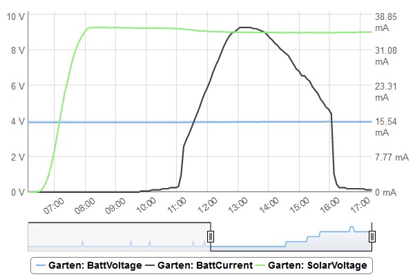
Can someone explain, why the charger isnt charging all the time or at least earlier? BattVoltage is 3.96V on the right end. Is the cell considered full?
-
Can someone explain, why the charger isnt charging all the time or at least earlier? BattVoltage is 3.96V on the right end. Is the cell considered full?
@rollercontainer For some reason current started to drop. Once it reached C/10 (around 10mA), charger stopped charging. This is a programmed function.
I can see two reasons why the current started to drop. Voltage readings might be off for one. Or the battery doesn't accept charge above 4V. Its internal resistance might risen.Late charge start might indicate wrong voltage readings. If we assume that in the morning the voltage is 4.2V, then at 11 o'clock the voltage dropped just enough for the charger to start charging (also a programmed feature).
-
I've built nodes using two versions of the Ceech board intended for solar cells - one with the LTC4079 charger, the other with the earlier LTC4067 charger.
I now want to use one of these as a pulse power sensor without sleep (as per MySensors example sketch), so it needs to be on non-battery power, i.e., from a 5V USB charger. If I remove the battery, which input should I connect the 5V to: the battery input or the solar input?
-
On the board with the LTC4079 there is a voltage regulator behind the input, so you can use battery connector. On the board with the LTC4067 use the VIN pin on the bottom connector.
-
Hello,
I use a My Sensors 2.0 version of "Multisensor node using @ceech board" but I have this error:TSP:MSG:SEND 5-5-0-0 s=255,c=3,t=11,pt=0,l=12,sg=0,ft=1,st=ok:JMP-LightLux TSP:MSG:SEND 5-5-0-0 s=255,c=3,t=12,pt=0,l=3,sg=0,ft=0,st=ok:1.0 TSP:MSG:SEND 5-5-0-0 s=10,c=0,t=13,pt=0,l=0,sg=0,ft=0,st=ok: TSP:MSG:SEND 5-5-0-0 s=11,c=0,t=13,pt=0,l=0,sg=0,ft=0,st=ok: TSP:MSG:SEND 5-5-0-0 s=1,c=0,t=16,pt=0,l=0,sg=0,ft=0,st=ok: Request registration... TSP:MSG:SEND 5-5-0-0 s=255,c=3,t=26,pt=1,l=1,sg=0,ft=0,st=ok:2 TSP:MSG:READ 0-0-5 s=255,c=3,t=27,pt=1,l=1,sg=0:1 Node registration=1 Init complete, id=5, parent=0, distance=1, registration=1 BH1750 lux: 387TSP:MSG:SEND 5-5-0-0 s=1,c=1,t=37,pt=3,l=2,sg=0,ft=0,st=ok:387 Batt: 3.74V ; 414.08mA Solar: 0.00V ; 0.00 mA; charge: Yes BattPct: 61% TSP:MSG:SEND 5-5-0-0 s=10,c=1,t=38,pt=7,l=5,sg=0,ft=0,st=ok:3.738 TSP:MSG:SEND 5-5-0-0 s=10,c=1,t=39,pt=7,l=5,sg=0,ft=0,st=ok:0.414 TSP:MSG:SEND 5-5-0-0 s=11,c=1,t=38,pt=7,l=5,sg=0,ft=0,st=ok:0.000 TSP:MSG:SEND 5-5-0-0 s=11,c=1,t=39,pt=7,l=5,sg=0,ft=0,st=ok:0.000 !TSP:MSG:SEND 5-5-0-0 s=255,c=3,t=0,pt=1,l=1,sg=0,ft=0,st=fail:61after that the node doesn't send data to gateway.
Do you have some ideas to solve the problem?
thanks