Easy/Newbie PCB for MySensors
-
Yesterday I have received Rev 9 of Newbie PCB board. I am a newbie and I purchased this board to make building easier. I have soldered a radio and Arduino Pro Mini 3.3 V to it and the radio module with a 47uF cap. The power is supplied using the FTD232 board. Because the radio module is not powered using the 3.3V of arduino I wired this using a separate wire. I also connected a DTH 11 with the resistor on the board (4K7). I used a test sketch to read the DTH 11 and this is working well.
When I load the MySensors sketch I get a radio failure. I have no Idea what this is? Bad wiring, not correct power?? Anyone can help me started?
0 MCO:BGN:INIT NODE,CP=RNNNA--,VER=2.1.1 4 TSM:INIT 4 TSF:WUR:MS=0 12 !TSM:INIT:TSP FAIL 14 TSM:FAIL:CNT=1 16 TSM:FAIL:PDT 10018 TSM:FAIL:RE-INIT 10020 TSM:INIT 10027 !TSM:INIT:TSP FAIL 10031 TSM:FAIL:CNT=2 10033 TSM:FAIL:PDT``` -
Yesterday I have received Rev 9 of Newbie PCB board. I am a newbie and I purchased this board to make building easier. I have soldered a radio and Arduino Pro Mini 3.3 V to it and the radio module with a 47uF cap. The power is supplied using the FTD232 board. Because the radio module is not powered using the 3.3V of arduino I wired this using a separate wire. I also connected a DTH 11 with the resistor on the board (4K7). I used a test sketch to read the DTH 11 and this is working well.
When I load the MySensors sketch I get a radio failure. I have no Idea what this is? Bad wiring, not correct power?? Anyone can help me started?
0 MCO:BGN:INIT NODE,CP=RNNNA--,VER=2.1.1 4 TSM:INIT 4 TSF:WUR:MS=0 12 !TSM:INIT:TSP FAIL 14 TSM:FAIL:CNT=1 16 TSM:FAIL:PDT 10018 TSM:FAIL:RE-INIT 10020 TSM:INIT 10027 !TSM:INIT:TSP FAIL 10031 TSM:FAIL:CNT=2 10033 TSM:FAIL:PDT```@martim said in Easy/Newbie PCB for MySensors:
Because the radio module is not powered using the 3.3V of arduino I wired this using a separate wire.
Can you show a picture of your setup and give more explanation on this sentence ? This part about connection of the radio smells fishy ;)
It seems the radio cannot be initialized, so I suppose the power supplied to it is not correct, but I'm not sure of what you did. -
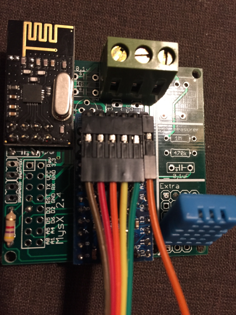
This is the front part. The connected cable goes to the FTD232 which also is currently the power supply.
 !
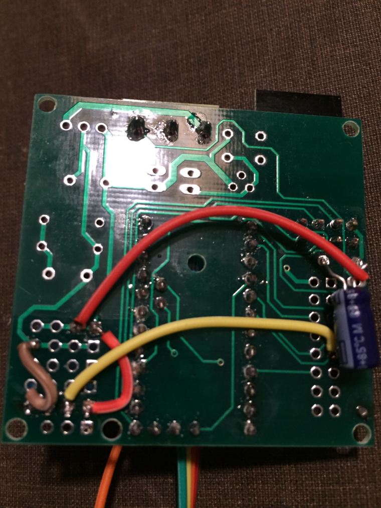
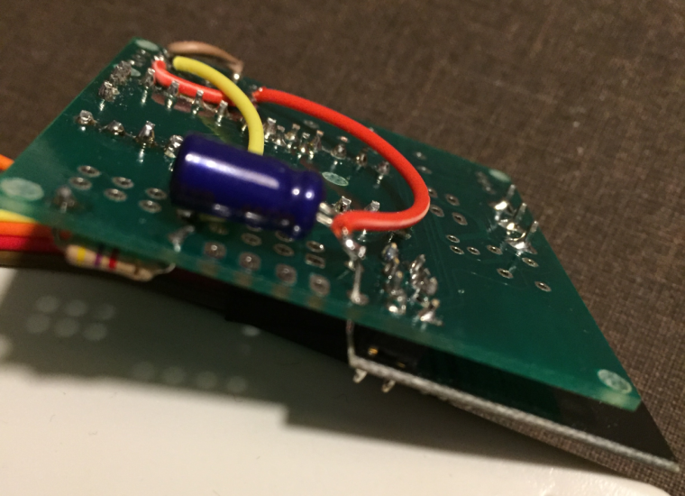
!The red wire on the back plane connects the plus from arduino to the plus for the radio (soldered on the + of cap)
0_1486835943373_IMG_3546.JPG !Try to zoom in.
0_1486835954003_zoomed.png -
This is the front part. The connected cable goes to the FTD232 which also is currently the power supply.
!The red wire on the back plane connects the plus from arduino to the plus for the radio (soldered on the + of cap)
0_1486835943373_IMG_3546.JPG !Try to zoom in.
0_1486835954003_zoomed.png@martim - read the insctructions again.
If you are using the board with a 3.3v arduino and battery you need to connect the BAT jumper and use a booster.If you are using a 3.3 arduino with a regulated power you can add a jumper/wire over the booster and connect the BAT jumper.
-
@martim - read the insctructions again.
If you are using the board with a 3.3v arduino and battery you need to connect the BAT jumper and use a booster.If you are using a 3.3 arduino with a regulated power you can add a jumper/wire over the booster and connect the BAT jumper.
@sundberg84
Ok, Thanks I will try the second suggestion. (my booster is still not delivered and hard to get at the moment :() -
Found one issue. On the PCB board the was a very small broken wire. I think the postman was not very careful with it. At least I have some better logging but still not there.
How can I solve this one?
0 MCO:BGN:INIT NODE,CP=RNNNA--,VER=2.1.1
4 TSM:INIT
4 TSF:WUR:MS=0
12 TSM:INIT:TSP OK
14 TSM:INIT:STATID=20
16 TSF:SID:OK,ID=20
18 TSM:FPAR
55 TSF:MSG:SEND,20-20-255-255,s=255,c=3,t=7,pt=0,l=0,sg=0,ft=0,st=OK:
2064 !TSM:FPAR:NO REPLY
2066 TSM:FPAR
2103 TSF:MSG:SEND,20-20-255-255,s=255,c=3,t=7,pt=0,l=0,sg=0,ft=0,st=OK:
4112 !TSM:FPAR:NO REPLY
4114 TSM:FPAR
4151 TSF:MSG:SEND,20-20-255-255,s=255,c=3,t=7,pt=0,l=0,sg=0,ft=0,st=OK:
6160 !TSM:FPAR:NO REPLY
6162 TSM:FPAR
6199 TSF:MSG:SEND,20-20-255-255,s=255,c=3,t=7,pt=0,l=0,sg=0,ft=0,st=OK:
8208 !TSM:FPAR:FAIL
8210 TSM:FAIL:CNT=1
8212 TSM:FAIL:PDT
Does this mean the gateway does not reply? It does with other sensors?
-
Found one issue. On the PCB board the was a very small broken wire. I think the postman was not very careful with it. At least I have some better logging but still not there.
How can I solve this one?
0 MCO:BGN:INIT NODE,CP=RNNNA--,VER=2.1.1
4 TSM:INIT
4 TSF:WUR:MS=0
12 TSM:INIT:TSP OK
14 TSM:INIT:STATID=20
16 TSF:SID:OK,ID=20
18 TSM:FPAR
55 TSF:MSG:SEND,20-20-255-255,s=255,c=3,t=7,pt=0,l=0,sg=0,ft=0,st=OK:
2064 !TSM:FPAR:NO REPLY
2066 TSM:FPAR
2103 TSF:MSG:SEND,20-20-255-255,s=255,c=3,t=7,pt=0,l=0,sg=0,ft=0,st=OK:
4112 !TSM:FPAR:NO REPLY
4114 TSM:FPAR
4151 TSF:MSG:SEND,20-20-255-255,s=255,c=3,t=7,pt=0,l=0,sg=0,ft=0,st=OK:
6160 !TSM:FPAR:NO REPLY
6162 TSM:FPAR
6199 TSF:MSG:SEND,20-20-255-255,s=255,c=3,t=7,pt=0,l=0,sg=0,ft=0,st=OK:
8208 !TSM:FPAR:FAIL
8210 TSM:FAIL:CNT=1
8212 TSM:FAIL:PDT
Does this mean the gateway does not reply? It does with other sensors?
@martim - yes, it doesnt get the connection to the GW as it wants... might be node or gw. Do you have caps on both?
-
Awesome board!!!
How do I access A2, A3 and D8?Thanks a lot
-
Awesome board!!!
How do I access A2, A3 and D8?Thanks a lot
@hiddenuser - they are not accesses through the PCB:
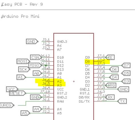
You need to solder a wire on the Pro Mini and run somewhere, like the prototyping area.
-
@hiddenuser - they are not accesses through the PCB:
You need to solder a wire on the Pro Mini and run somewhere, like the prototyping area.
@sundberg84 Thanks a lot.... My ebay seller sent me a Atmega168 5v. I have noticed that you boards supports 5v version too. Would I be able to power it using raw (12v).
Thanks a lot .
-
@sundberg84 Thanks a lot.... My ebay seller sent me a Atmega168 5v. I have noticed that you boards supports 5v version too. Would I be able to power it using raw (12v).
Thanks a lot .
@hiddenuser - as long as the voltage divider on the board supports 12v that will work. A warning on the cheap chinese stuff is that this voltage regulator is bad and might fry.
-
@hiddenuser - as long as the voltage divider on the board supports 12v that will work. A warning on the cheap chinese stuff is that this voltage regulator is bad and might fry.
-
@sundberg84 - thanks for your board, it seems to be almost exactly what I was looking for! What do you think would be the best way to adjust it if I need to boost the batteries not only to 3.3V, but also to 5V to run the pir sensor?
@achurak1 - do you mean running 5v on batteries? Sorry - thats out of my knowledge.
I guess there are 5v boosters but my guess is also that this will drain the batteries pretty fast.
I have made test with 9v batteries and voltage regulaters and this has worked for some time but never gives the lifetime as 3.3v on 2xAA. -
@achurak1 - do you mean running 5v on batteries? Sorry - thats out of my knowledge.
I guess there are 5v boosters but my guess is also that this will drain the batteries pretty fast.
I have made test with 9v batteries and voltage regulaters and this has worked for some time but never gives the lifetime as 3.3v on 2xAA.@sundberg84 - correct, the 5v booster looks exactly like the 3.3v booster. I have another sensor I've built manually and it works exactly like that, arduino/temp/hum/radio all work from 3.3v and pir works from 5v. I power it all with two rechargeable batteries (so ~2.6 max charged, not even 3) and it's been running good for several months already and still shows 2.45-2.50.
-
@sundberg84 - correct, the 5v booster looks exactly like the 3.3v booster. I have another sensor I've built manually and it works exactly like that, arduino/temp/hum/radio all work from 3.3v and pir works from 5v. I power it all with two rechargeable batteries (so ~2.6 max charged, not even 3) and it's been running good for several months already and still shows 2.45-2.50.
-
@achurak1 do you know you could modify the pir sensor to work directly from batteries by removing the regulator?
@gohan - I tried to connect the 3.3v to one of the three pins where you'd usually put a jumper (H, L pads) as I've seen people discussing it on this forum and it just didn't work for me, the sensor did work, but very unstable, would fire up every time radio sends or receives something.
-
Because you need to add an extra AA battery to increase voltage to around 4,5v just for the pir sensor
@gohan - not sure how exactly it answers my question? I thought you meant I could run the pir from 3.3v. I could plug everything to an outlet and don't worry about the batteries at all. The pir works perfectly from two batteries and the 5v booster, so why would I want to add more batteries and make the whole thing much bigger?