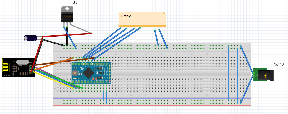
Powering problem with nano and 4 relays
-
Try running relay-ground through the arduino and not directly to source gnd?
-
The fritzling looks ok.
Speculating: Could it for some reason pull too much from the gpios when controlling the relays?
If you have a multimeter, measure the current on one of the gpios, when turning on a relay.@hek The currunt is 0,002A from arduino pin4 to IN2 on the relay board
@sundberg84 Din't work with the GND from the arduino
Update it will only work when it's connected USB to the PC with the monitor program and remove the jumper on the relay board (JD-VCC - VCC current 0,308A).
-
I think you should start by measuring voltage across VCC and GND on your Arduino pins when USB is not connected. On a lot of these breadboards "GND" and "VCC" rails are not connected the whole "width". Its not unusual that VCC is separated into two rails. Sometimes both VCC and GND are separated in the center of the rails.
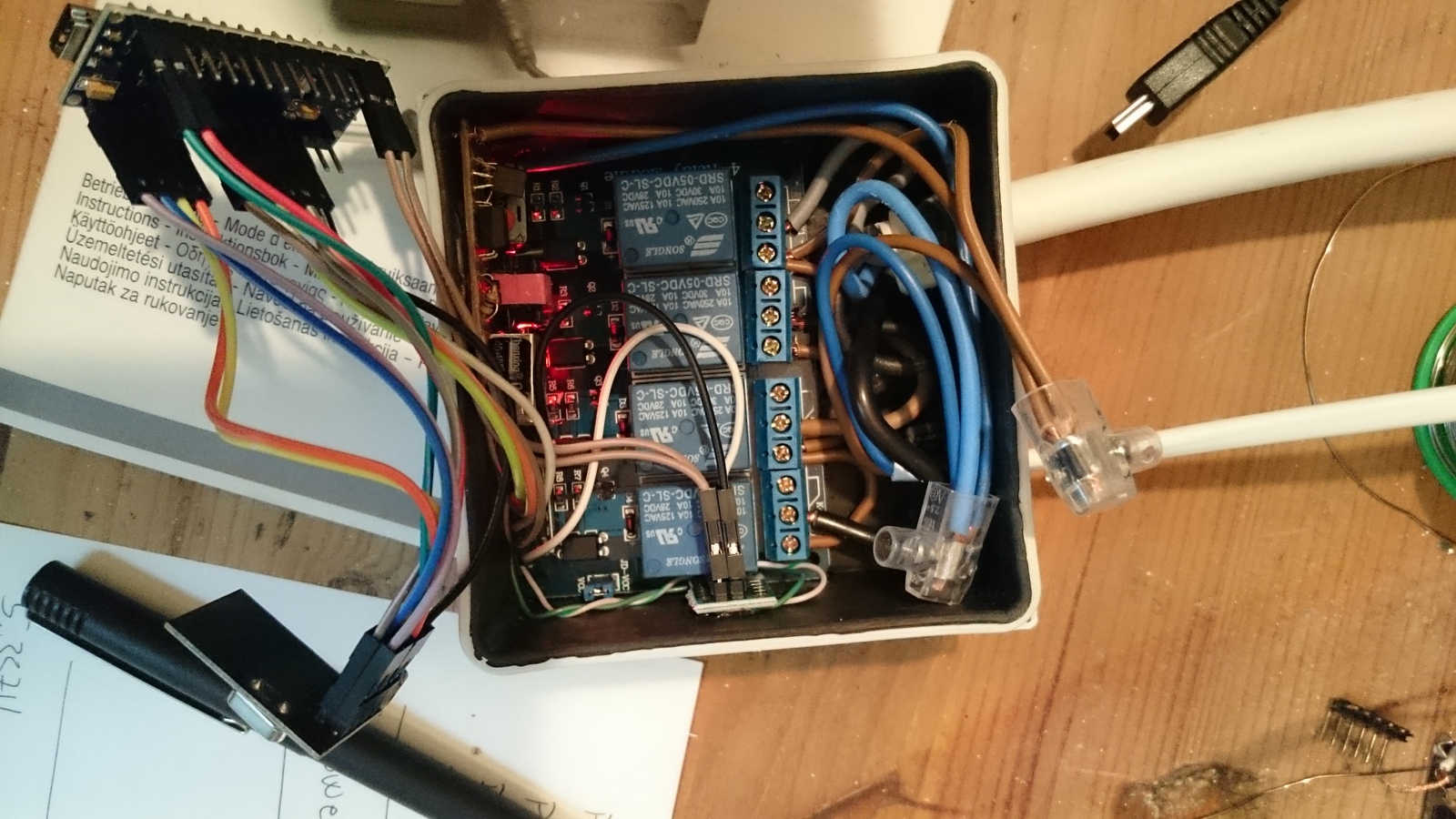
Of course I can't see your actual setup but if it looks something like that image it can be a good idea to check connections between DC-plug and VCC/GND on you Arduino.
Worth a try.
-
I think you should start by measuring voltage across VCC and GND on your Arduino pins when USB is not connected. On a lot of these breadboards "GND" and "VCC" rails are not connected the whole "width". Its not unusual that VCC is separated into two rails. Sometimes both VCC and GND are separated in the center of the rails.
Of course I can't see your actual setup but if it looks something like that image it can be a good idea to check connections between DC-plug and VCC/GND on you Arduino.
Worth a try.
Hello! It looks like you're interested in this conversation, but you don't have an account yet.
Getting fed up of having to scroll through the same posts each visit? When you register for an account, you'll always come back to exactly where you were before, and choose to be notified of new replies (either via email, or push notification). You'll also be able to save bookmarks and upvote posts to show your appreciation to other community members.
With your input, this post could be even better 💗
Register Login